 31 May 10
[ Home ] [ Up ] [ Previous Page ] [ Next Page ]
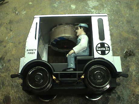
31 May 10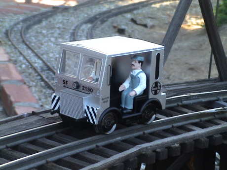 A USA Trains Speeder followed
me home from the Big Train Show this afternoon. I managed to get it
on the track for a little testing before actually packing to go on
travel for about 8 weeks. It ran pretty well. The track hadn't been
cleaned in a month and was pretty heavily oxidized but it ran. It
sputtered, but it ran. I ran the pole sander over the main line and
then it ran just fine. I also ran it in analog mode with DCC on the
track and besides for the typical DCC buzz in an analog loco, it
also ran fine. There is a light amount of gear noise but it runs
quite smoothly.
A USA Trains Speeder followed
me home from the Big Train Show this afternoon. I managed to get it
on the track for a little testing before actually packing to go on
travel for about 8 weeks. It ran pretty well. The track hadn't been
cleaned in a month and was pretty heavily oxidized but it ran. It
sputtered, but it ran. I ran the pole sander over the main line and
then it ran just fine. I also ran it in analog mode with DCC on the
track and besides for the typical DCC buzz in an analog loco, it
also ran fine. There is a light amount of gear noise but it runs
quite smoothly.
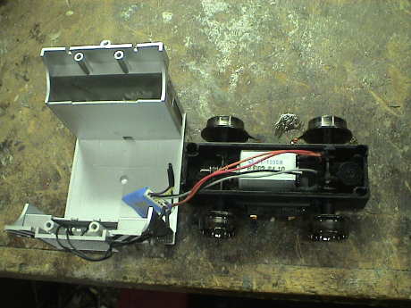
The speeder is not feature heavy. All it has is a motor and a non-directional headlight. There are no conventional couplers, but there is a drawbar of sorts at the rear.
It tracks well and power pickup is reliable as long as the wheel wipers don't get bent. However, the speeder is small and light so it is intolerant of debris on the track. Hit a leaf or twig and it'll derail immediately.
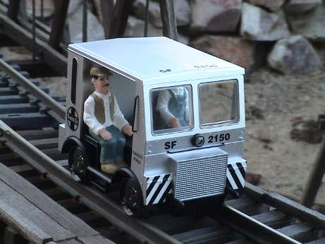 The speeder picks up power on
four wheels, but only the rear two are powered, similarly to the
Lionel Handcar. The power pickups are metal wipers that ride on the
backs of the wheels. I checked the motor current and it is very
low. At 18 volts running light, it draws between 60 and 70 mA. At
full stall, it draws 700 mA. An HO or even N scale DCC decoder will
do fine in this one provided that I can find the room. However,
this will have to wait for a couple of months as I will be out of
town for most of that time.
The speeder picks up power on
four wheels, but only the rear two are powered, similarly to the
Lionel Handcar. The power pickups are metal wipers that ride on the
backs of the wheels. I checked the motor current and it is very
low. At 18 volts running light, it draws between 60 and 70 mA. At
full stall, it draws 700 mA. An HO or even N scale DCC decoder will
do fine in this one provided that I can find the room. However,
this will have to wait for a couple of months as I will be out of
town for most of that time.
 DCC
installation in the Speeder is a piece of cake. The only real issue
is finding room for an HO scale decoder, I used a Digitrax DH163D
(wired) decoder because I had one and I could evaluate how DCC
would work in this loco without spending any money. The plan was
that if it worked, I'd consider buying some HO sound decoder and
return the DH163 to stock.
DCC
installation in the Speeder is a piece of cake. The only real issue
is finding room for an HO scale decoder, I used a Digitrax DH163D
(wired) decoder because I had one and I could evaluate how DCC
would work in this loco without spending any money. The plan was
that if it worked, I'd consider buying some HO sound decoder and
return the DH163 to stock.
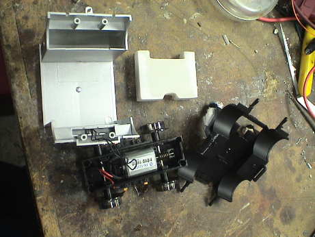
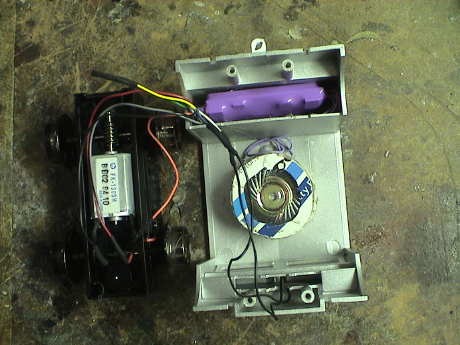
There are four screws in the motor block that release the block
from the body. Then the bottom part of the body will come out by
gently prying on the "lift handles" at either end. There is a cast
resin weight in the rear of the car. This guy completely fills a
cavity that is ideal for stashing the decoder. The obvious solution
is to ditch the 1.4 oz weight and replace it with a similar amount
of something denser, such as lead. This then leaves volume
available to stash the decoder.
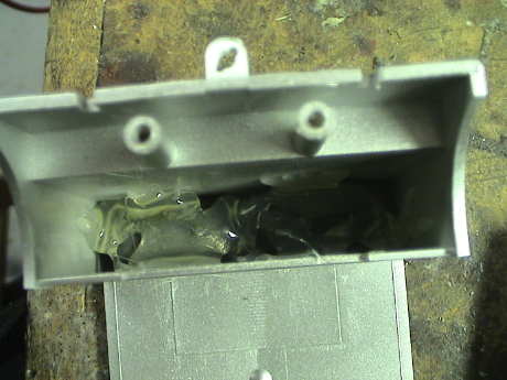 I
used two 1 oz fishing weights, held in with a liberal amount of hot
glue. You could also pour lead shot (recovered from a few 12 ga
shotgun shells) and then bind it in with hot glue, silicone sealer
matte medium or diluted wood glue.
I
used two 1 oz fishing weights, held in with a liberal amount of hot
glue. You could also pour lead shot (recovered from a few 12 ga
shotgun shells) and then bind it in with hot glue, silicone sealer
matte medium or diluted wood glue.
 The
Speeder uses a black and red wire to connect the track directly to
the motor. These wires are reversed in position as compared to HO
standards, but large scale also reverses the track polarity. If you
are interested in having the Speeder analog convert properly, then
just follow the HO color guidelines and ignore the left and right
stuff. Then it will work fine. I cut the headlight wires off right
next to the motor and then cut the red and black wires at the
highest portion of their loop when they are pulled out as far as
they will go. The red and black decoder leads go to the red and
black power pickup wires. The gray decoder wire goes to the black
motor wire, the orange decoder wire goes to the red motor wire. I
wired up the headlight to be on in the forward direction only using
the blue and white decoder wires. The lamp is incandescent so it
doesn't care about polarity. It also draws only 23 mA at 20 volts
so it doesn't need a current limiting resistor either.
The
Speeder uses a black and red wire to connect the track directly to
the motor. These wires are reversed in position as compared to HO
standards, but large scale also reverses the track polarity. If you
are interested in having the Speeder analog convert properly, then
just follow the HO color guidelines and ignore the left and right
stuff. Then it will work fine. I cut the headlight wires off right
next to the motor and then cut the red and black wires at the
highest portion of their loop when they are pulled out as far as
they will go. The red and black decoder leads go to the red and
black power pickup wires. The gray decoder wire goes to the black
motor wire, the orange decoder wire goes to the red motor wire. I
wired up the headlight to be on in the forward direction only using
the blue and white decoder wires. The lamp is incandescent so it
doesn't care about polarity. It also draws only 23 mA at 20 volts
so it doesn't need a current limiting resistor either.
The decoder is then stuffed up into the body and the floor is reinstalled. Then the motor brick is reattached with the original screws and it's done. It worked right off, no problems.
 The DH163D
was working fine in the Speeder but it doesn't provide sound. The
Speeder is one of the last locos that I have that ran in stealth
mode. So the DH163D came out and a Soundtraxx Tsunami went it. The TSU-1000
sound decoder isn't very suitable for large scale because it is
rated for 1 amp stall current, a spec that few large scale locos
can meet. However, the Speeder draws only 700 mA at full stall so
the Tsunami could handle it. It also just barely fit.
The DH163D
was working fine in the Speeder but it doesn't provide sound. The
Speeder is one of the last locos that I have that ran in stealth
mode. So the DH163D came out and a Soundtraxx Tsunami went it. The TSU-1000
sound decoder isn't very suitable for large scale because it is
rated for 1 amp stall current, a spec that few large scale locos
can meet. However, the Speeder draws only 700 mA at full stall so
the Tsunami could handle it. It also just barely fit.
The wiring was very simple, all the wire colors matched those of the DH163 except for the two purple speaker wires. The Tsunami uses an 8 ohm speaker and makes pretty good volume as compared to other HO sized decoders. I originally tested it with a much better speaker, this one cannot reproduce the bass but it does well enough.
The Tsunami produces a wide range of sounds and the decoder supports BEMF, this is a good decoder for small locos that can handle it.
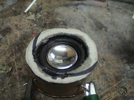
 After filling
up the back completely with weight and the decoder, the speaker had
to go somewhere. This is a 1" 8Ω speaker that came with a
Dallee system. I made an enclosure out of a cardboard tube and hot
glue. The enclosure will have to get painted, probably silver to
match the rest of the unit.
After filling
up the back completely with weight and the decoder, the speaker had
to go somewhere. This is a 1" 8Ω speaker that came with a
Dallee system. I made an enclosure out of a cardboard tube and hot
glue. The enclosure will have to get painted, probably silver to
match the rest of the unit.
 Eventually, I
built a whole new speaker enclosure with a "high bass" speaker. The
enclosure is still made from cardboard (model rocket body tube and
some scrap cardboard) but this time I assembled it with Zap-A-Gap
CA and it came out a little neater. It sounds better too as can be
heard in this Quicktime
movie.
Eventually, I
built a whole new speaker enclosure with a "high bass" speaker. The
enclosure is still made from cardboard (model rocket body tube and
some scrap cardboard) but this time I assembled it with Zap-A-Gap
CA and it came out a little neater. It sounds better too as can be
heard in this Quicktime
movie.
The Tsunami sound decoder never really liked the high track voltage, 22 VRMS, at the GIRR very much. It would complain by blinking it's headlight fairly often. This indicates an error condition. I finally elected to do something about it after Greg Elmassian commented about the poor reliability his Tsunami exhibited on his higher track voltage of 24 volts. The Tsunami is rated at 22 volts, but it is an HO decoder and would have not been extensively used or tested by Soundtraxx at 22 volts.
 One way to drop the input voltage
is with a resistor, but then the voltage drop depends on load
current as well. Another way to do it is with a simple
bidirectional diode stack. The four diodes in this stack produce a
drop of 2.8 volts total, enough to get the voltage down near 19
volts which provides some margain against the specification. I used
1N4005 diodes for this stack, but virtually any 1 amp silicon
rectifier will work since the Tusnami is rated at only 1 amp
anyway.
One way to drop the input voltage
is with a resistor, but then the voltage drop depends on load
current as well. Another way to do it is with a simple
bidirectional diode stack. The four diodes in this stack produce a
drop of 2.8 volts total, enough to get the voltage down near 19
volts which provides some margain against the specification. I used
1N4005 diodes for this stack, but virtually any 1 amp silicon
rectifier will work since the Tusnami is rated at only 1 amp
anyway.
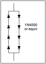
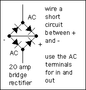 A
somewhat easier way to wire a diode stack is to use a bridge
rectifier. The diagram shows an application with a high current
bridge, but any cheap 1 amp bridge will work with the Tsunami. Use one bridge rectifier for each 1.4 volts of desired drop.
A
somewhat easier way to wire a diode stack is to use a bridge
rectifier. The diagram shows an application with a high current
bridge, but any cheap 1 amp bridge will work with the Tsunami. Use one bridge rectifier for each 1.4 volts of desired drop.
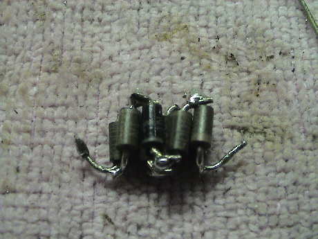 My parts box yielded
some 1N4005 (400 volt) diodes that I got as surplus somewhere for
about a penny each. The leads were cleaned and bent and the diodes
soldered together in a compact stack. The soldering looks pretty
bad because these diodes probably failed a solderability test, they
didn't wet well even after being scraped clean.
My parts box yielded
some 1N4005 (400 volt) diodes that I got as surplus somewhere for
about a penny each. The leads were cleaned and bent and the diodes
soldered together in a compact stack. The soldering looks pretty
bad because these diodes probably failed a solderability test, they
didn't wet well even after being scraped clean.
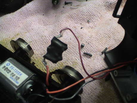 The stack was
enclosed in a piece of shrink tube and inserted in series with a
track lead.
The stack was
enclosed in a piece of shrink tube and inserted in series with a
track lead.
The tendency of the decoder to issue an error did not go completely away, but it happened much less often. I saw it only once during my testing, I would have expected it to be doing about half the time like it used to. It is probably telling me that it want's lower voltage yet.
I discovered by accident (a broken solder joint) that this decoder, and probably most others, will actually run from a half wave rectified DCC signal, albiet slowly. If you want to cut your voltage in half, then a single diode will do the job.
[ Home ] [ Up ] [ Previous Page ] [ Next Page ]
This page has been accessed times since 6 Jun 09.
© 2009-2010 George Schreyer
Created 6 Jun 09
Last Updated May 3, 2010