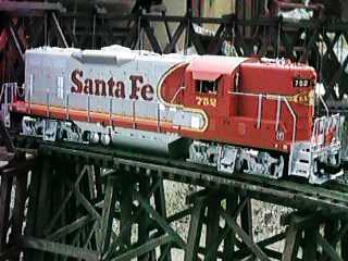
 USA Trains has released is
second diesel, a GP7 or GP9 depending on the road name desired. My
first impression is that this is a fine engine. It runs very
smoothly and pulls very well.
USA Trains has released is
second diesel, a GP7 or GP9 depending on the road name desired. My
first impression is that this is a fine engine. It runs very
smoothly and pulls very well.USA Trains has released is
second diesel, a GP7 or GP9 depending on the road name desired. My
first impression is that this is a fine engine. It runs very
smoothly and pulls very well.
Note that this particular unit is an old one, purchased in 1998. Newer models may have signficantly different circuit boards of various types and the lighting voltages may be either 5 or 12 volts. This unit has four switches underneath, newer models may have five.
The GP7 and the later GP9 were developed by EMD and first released in 1949. The engine was intended to be a lower cost version of the cab type units that had come before. This was actually EMD's second attempt, after the ill-fated BL-2, at the road switcher market. The intention was to make an engine that had good engineer visibility both fore and aft and was easy to maintain. EMD thought that the resultant engine was so ugly that no self respecting railroad would allow one on the main line. They were obviously wrong. The "Geep" was used in every kind of service on railroads all over the country. Many were equipped with steam generators and were used in passenger service as well. There were also cabless "B" units of the GP9 made as well, but the vast majority were "A" units.
These units proved so versatile that instead of scrapping them at the end of their normal lives, many railroads elected to rebuild them instead. Some got chopped noses and are still in service. ATSF called theirs a GP9u (numbered in the 2650 class) and I still see them nearly every day on the LA Harbor Sub. Other railroads rebuilt them in their original configuration or cut them down into slugs.
The Warbonnet version of the USA Trains GP9 is numbered 752. There is a class of GP9 ATSF locos shown on the Santa Fe Locomotive Drawings page that is numbered from 700 to 751 that looks like this engine. I could not find another engine numbered 752. The same class is shown in the ATSF All Time Diesel Roster that has the same information. Since it unlikely that ANY GP9 was ever painted in Warbonnet, maybe USA Trains decided to number this model as the next one that would have been purchased.
 19 Feb 09
The first thing that I noticed when I dropped the GP9 on the track is that there was a very audible gear noise. I thought that I wasn't off to a very good start, but it turns out that the gear noise is about the only thing that I found wrong or even slightly objectionable. As the engine was run in, the worst of the noise went away. When it was new, the noise was roughly equal running forward or backward. After some break-in time forward the noise was louder and harsher running backward than running forward. After extended running in both directions, the noise has settled down at the "light whine" level.
The gear train is a straight forward worm gear drive with an exceptionally large can motor in each truck.
[ Top ]
Aside from the gear noise, the engine runs VERY well and very smoothly. It starts and runs at lower track voltage than the pair of Aristo RS-3's that I tested it with. At about 10 scale mph, the GP9 and the RS-3s run at the same speed. At higher speeds the GP9 runs maybe 1% slower than the RS-3's. This close speed matching allows the Aristo diesels and the GP9 to run in MU operation without having to mess with either. At all speeds in either direction there is very little bucking between the engines.
The excellent slow speed capability of the USA Trains GP-7/9 makes operation with Kadee couplers very easy. It is no problem to smoothly start and stop the engine over an uncoupler magnet and the smooth push allows spotting of cars away from the magnet to be highly reliable.
The pulling power of the GP9 is good as well. In my standard traction test, it'll handle 14 cars nicely on a 1.6% grade, see my Tractive Effort Tests page for the data. The engine has four traction tires, two on each truck.
Power is picked up on all eight wheels through the wheel journals AND the wheel bearings in addition to four track sliders. The engine does slow somewhat on a sections of really cruddy track, but tends not to stall, jerk or sputter. When the engine was new, power pickup reliability was excellent. After a period of time, the sliders packed up with crud (I don't keep my track really clean) and power pickup suffered as a result. Further, the four wheels with traction tires don't contribute much to power pickup. The sliders themselves seem to wear faster than LGB sliders as after a hundred hours or so of running, they are deeply grooved. A quick pass with a Brite Boy will clean off the sliders.
After a year of use, the wheels without the traction tires have become very pitted and now do not make reliable connection to the track. Combine that with crudded up sliders, and the engine has become sensitive to dirty track. I wired it with power connectors so that it could pick up power from its train or another engine and it is much better. Better wheels seem to fix this problem, see GP9 Wheel Upgrades later in this page.
The trucks are flexible and as a result, the engine is very sure footed. It tends not to derail, even under really bad conditions. There are lots of dried ivy leaves and stems in my yard and the wind repositions them all the time. Even though the engine continually runs over them, it just crumbles them up and spits out what is left without leaving the track.
The engine has directional headlights that are clearly visible in daylight although they don't cast a real strong beam at night. The large number boards and the cab are also illuminated. There are marker lights that change color depending on the engine direction, green to the front, red to the rear.
The GP-7/9 has a very high motor stall current, more than 10 amps steady state by actual test. This is obvious during bench tests as well. Just applying 18 volts to the unloaded engine causes the current meter on my power supply to spike past 8 amps. Further, I assume that the real peak is higher than that, the meter just can't respond fast enough. If you add DCC or R/C to this engine, you will have to be careful to properly size the motor controller or you will probably burn up the motor controller. This is the main reason that I have not yet installed DCC in this engine. After speaking with several DCC decoder manufacturers for their recommendation for the proper DCC decoder for this engine, none of them wanted their decoders installed in the GP9. All have had too much trouble with warranty returns, even when two decoders were used. Measured right at the motor, the stall current is 15 amps per motor, beyond the capability of almost all currently manufactured DCC decoder. The stall current of the entire engine is less due to the parasitic resistance of the power wiring in the engine. You can find more data on these motors in my DCC Tips page.
The high motor stall current has both an upside and several downsides. The upside is exceptionally good low speed performance. The torque of a small DC motor is directly proportional to motor current. The low motor impedance (resulting in high stall current) allows the motors to draw adequate current to make usable torque at low voltage and therefore low motor speed. This allows the loco to perform very well in heavily loaded low speed switching service. However, this capability comes (in my humble opinion) at very high cost. These costs are that the high peak currents stress power supplies, wheel contacts, motor controllers and drain batteries rapidly (when used). When used with battery power or DCC, these high current motors are a significant drawback. None of the advantages of high stall current are realized but all of the liabilities are.
[ Top ]
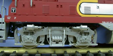
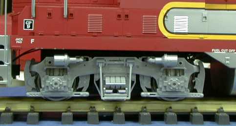
By my measurements, the model is acceptably close to 1/29 scale. I get 1/28.8 scale in width, 1/29 scale in length and 1/29.6 scale in height based on EMD's builders drawings. The sprung trucks are a reasonable facsimile of a Blomburg Type B truck. The wheel base is the correct 9' on the money at 1/29 scale. I believe that the scale height of the engine is off due to the small wheels, they scale out to under 33" instead of the more correct 40".
Even though the engine is large, clearance issues are not terribly severe. The foot boards are high enough to clear either Aristo or LGB turnout motors, even on tight radius track. The outside overhangs generally aren't worse than a Big Hauler. Most clearances are considerably relaxed from a Bachmann Shay, so if a Shay fits, the GP9 will do fine. However, there are some clearance issues that has come up with the GP9.
The motor bricks hang pretty low, they clear the railheads by only 0.07". One user has complained that the bricks hang up on LGB rack rail and on LGB station platforms. I don't have either of these items to check against, but it could be close. A Bachmann Shay is pretty low underneath, but it has much more clearance at about 0.15". An Aristo diesel brick clears by 0.2". The GP9 clears Kadee uncoupler magnets fine.
There was another discussion on the Internet about clearance between the strap hangers on the Blomburg Type "B" trucks and LGB EPL turnout motors. One user was having serious interference problems. I took my GP9 outside and measured the clearance using styrene strips as feeler gauges. I found that the strap hangers were indeed VERY close to the tops of the motors, but they did clear in my case. Clearance was 0.01" (0.25 mm) to 0.06" (1.5 mm) depending on which strap hanger I measured against various turnout motors. This is about the same clearance that I get with the brake hangers on the Bachmann Shay. Larger aftermarket wheels will fix both of these clearance problems.
The motor, lights, sound and smoke switches are rather inconveniently located on the bottom of the engine. They are clearly labeled, but it is difficult to reach them without picking up the engine. Besides, I never can remember which one is which and I still find myself picking up the engine to read the labels.
[ Top ]
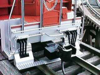 A Kadee 831 coupler mounts right on the
engine by following the included instructions for mounting the
included USA Trains knuckle coupler. The height comes out just
right once a slight modification is made to the coupler mount. The
mounting screw that comes with the hook and loop coupler is too
short to use with the Kadee coupler and the Kadee supplied screws
are a little too small. I found some suitable screws in my junk box
before I realized that I could have probably used the screws that
come with the supplied USA Trains knuckle couplers. The coupler
swing is too restricted to allow the use of knuckle couplers on 2'
radius curves. Derailments are a certainty.
A Kadee 831 coupler mounts right on the
engine by following the included instructions for mounting the
included USA Trains knuckle coupler. The height comes out just
right once a slight modification is made to the coupler mount. The
mounting screw that comes with the hook and loop coupler is too
short to use with the Kadee coupler and the Kadee supplied screws
are a little too small. I found some suitable screws in my junk box
before I realized that I could have probably used the screws that
come with the supplied USA Trains knuckle couplers. The coupler
swing is too restricted to allow the use of knuckle couplers on 2'
radius curves. Derailments are a certainty.
An LGB knuckle coupler will fit right on and comes out at the right height, however, it too is restricted to 4' or larger radius curves.
The coupler mounting tang is allowed to rotate to allow the couplers to deal with the large coupler overhang. I found that the vertical slop in this mount was just a little too much for Kadee couplers which are very sensitive to proper mounting height. The coupler would droop down just enough to allow the trip pin to catch on the track in turns and through turnouts. Filing about 20 mils off the mounting screw post allows the mounting screw to be tightened just enough to remove virtually all of this slop and still allows the tang to rotate freely.
The coupler centering spring is a little weak so that the coupler doesn't center precisely every time. This will need a little work.
I took the engine to the GIRR, Mountain Division where 2' curves are everywhere. The engine looks pretty silly on curves that tight, it is just too big. The coupler overhang is severe. I was able to couple and haul cars with hook and loop couplers, but ONLY with asymmetrical couplers (hook and loop on the engine, loop only on the following car). The engine and test car worked OK on the tight curves and even S curves, forward and backward. When I added a hook to the following car, the engine dragged it off the track on the first turn.
[ Top ]
The GP9 has two smoke generators which work quite well. The engine comes with both plastic and metal stacks. The instructions indicate that if the smoke generators are to be used, the metal stacks must be used to handle the heat. The problem is that the metal stacks are held in only by gravity and if you turn the engine over to access the smoke switch on the bottom, the stacks will fall out and they could get lost easily. If they are used, they should be attached with adhesive.
The instructions indicate that the rear stack may smoke more than the front stack. This is actually true. The rear stack puts out more smoke than the front stack.
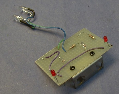
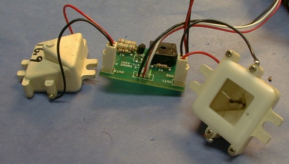 The smoke system consists
of a regulator board, the two smoke units and a remotely mounted
regulator transistor. Be careful when removing this assembly. Three
of the four mounting posts broke off while I was removing the
screws. I reattached the posts with Zap-A-Gap CA and was very
careful when reinstalling the screws.
The smoke system consists
of a regulator board, the two smoke units and a remotely mounted
regulator transistor. Be careful when removing this assembly. Three
of the four mounting posts broke off while I was removing the
screws. I reattached the posts with Zap-A-Gap CA and was very
careful when reinstalling the screws.
 The smoke elements themselves
seem to be similar to Bachmann elements. To me, this means that
they are not long for this world. However, its been four years
since I got this loco and both are still holding together.
The smoke elements themselves
seem to be similar to Bachmann elements. To me, this means that
they are not long for this world. However, its been four years
since I got this loco and both are still holding together.
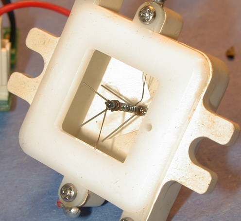
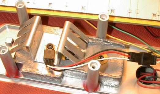 The smoke
unit regulator makes quite a bit of heat so that it is mounted to
the frame with a finned heat sink. This part is a Motorola TIP122
Darlington pair integrated circuit.
The smoke
unit regulator makes quite a bit of heat so that it is mounted to
the frame with a finned heat sink. This part is a Motorola TIP122
Darlington pair integrated circuit.
 This is a schematic of
the smoke circuit regulator. This is a constant current regulator.
The two 1.5 ohm resistors sense the current in the smoke elements.
If the smoke element current increases, the base voltage of the
2N3904 increases and it in turn drags down the base of the TIP122
pass transistor which reduces the voltage and therefore the current
of the smoke elements. The circuit regulates the current to about 1
amp. The resulting voltage across the elements is about 6 volts.
The most significant internal voltages are shown in red referenced
to the (-) side of the bridge.
This is a schematic of
the smoke circuit regulator. This is a constant current regulator.
The two 1.5 ohm resistors sense the current in the smoke elements.
If the smoke element current increases, the base voltage of the
2N3904 increases and it in turn drags down the base of the TIP122
pass transistor which reduces the voltage and therefore the current
of the smoke elements. The circuit regulates the current to about 1
amp. The resulting voltage across the elements is about 6 volts.
The most significant internal voltages are shown in red referenced
to the (-) side of the bridge.
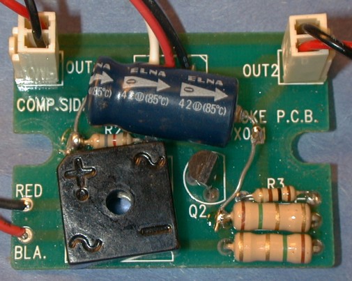 The 50 uF capacitor shown
on the schematic is a standard modification to improve the
performance of this kind of regulator when running at low speed and
with Aristo PWC. If you don't use PWC, the capacitor will do no
good. The capacitor is soldered between the + and - terminals of
the bridge rectifier circuit. These points are shown in the
photo.
The 50 uF capacitor shown
on the schematic is a standard modification to improve the
performance of this kind of regulator when running at low speed and
with Aristo PWC. If you don't use PWC, the capacitor will do no
good. The capacitor is soldered between the + and - terminals of
the bridge rectifier circuit. These points are shown in the
photo.
The downside of using a current regulator for this function is that the smoke units can't control their own current. A well designed smoke element will increase in resistance as it gets too hot and tend to self regulate its temperature. With this circuit, as the element heats and its resistance increases, the regulator just keeps pushing the current and the unit gets hotter yet. Further, if one of the elements burns out, the regulator will push ALL the current through the other element and cremate it in a short second. I would expect some sort of serious problems when this happens as the remaining element will probably glow white before it goes.
To avoid meltdown of the second smoke element in case of one element failure, a clamp diode can be put at the base of the pass transistor. This essentially turns the unit into a constant voltage regulator if the output voltage should try to rise. Alternately, a 7.5 volt zener diode could be used by simply shorting out the 1.5 ohm sense resistors. This will cause the 2N3904 to shut off and the base voltage on the TIP122 to clamp at 7.5 volts and limit the output voltage to 6.1 volts which is just right for these smoke elements.
 For DCC
installations, wiring the smoke units in parallel is a waste of
current. Since high track voltage is available all the time, it
isn't necessary to have the smoke units work at low voltage. If the
elements are rearranged in series, then the current drops by half
AND there is no risk of melting down the second unit when the first
one fails. As soon as either unit fails, BOTH will go off. Further,
the dissipation of the pass transistor drops by a factor of about
four. To reset the current to a lower level, one of the 1.5 ohm
sense resistors needs to be lifted at one end.
For DCC
installations, wiring the smoke units in parallel is a waste of
current. Since high track voltage is available all the time, it
isn't necessary to have the smoke units work at low voltage. If the
elements are rearranged in series, then the current drops by half
AND there is no risk of melting down the second unit when the first
one fails. As soon as either unit fails, BOTH will go off. Further,
the dissipation of the pass transistor drops by a factor of about
four. To reset the current to a lower level, one of the 1.5 ohm
sense resistors needs to be lifted at one end.
[ Top ]
USA Trains offers a sound system for the GP-7/9 but I don't have one. From the information that I have seen, I strongly suspect that it is a PH Hobbies unit similar to the unit offered for the Aristo RS-3.
USA Trains also offers a remote control box that is supposed to allow the horn, whistle and cab chatter to be operated remotely. The offer also indicates that the control unit could be used to trigger other kinds of sound systems is available as well.
I've done a sound system install in the GP9. Since this went in at the same time as a DCC conversion, I've installing a DCC based sound system, the Soundtraxx DSX. This is a system that is really intended for HO installations but it has the sound of an EMD 567. The audio output power of the DSX is weak by large scale standards so I knew that I needed to mount the speaker facing upward or it just wouldn't work very well. There is a spot in the fuel tank for a speaker but it faces down and the sound volume wouldn't be good enough.
I typically use 2"x 3-5/8" oval 6 watt computer speaker. I bought a pile of these at a local swap meet for cheap and I use them everywhere because they are easier to fit in many places that a round speaker won't fit. The speaker that Aristo uses in the RS-3 is the same size.
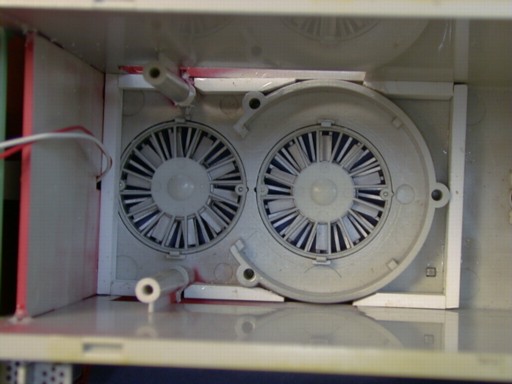 The easiest
spot to put the speaker in the GP9 is under the two fans next to
the cab. To seal the speaker, I needed to build a fence to prevent
the sound emitted from the rear of the speaker from interfering
with the desired sound from the front. A fence of 0.25" by 0.125"
styrene was built and fitted around the features in the hood.
The easiest
spot to put the speaker in the GP9 is under the two fans next to
the cab. To seal the speaker, I needed to build a fence to prevent
the sound emitted from the rear of the speaker from interfering
with the desired sound from the front. A fence of 0.25" by 0.125"
styrene was built and fitted around the features in the hood.
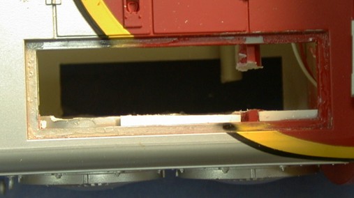 Two of
the hood mounting posts are in the way but since the posts are
attached to the side of the hood for the whole length of the post,
I could just trim out a short section to allow the speaker to fit.
The grills on the side of the hood pop out easily to make it easy
to hack out a section of the post.
Two of
the hood mounting posts are in the way but since the posts are
attached to the side of the hood for the whole length of the post,
I could just trim out a short section to allow the speaker to fit.
The grills on the side of the hood pop out easily to make it easy
to hack out a section of the post.
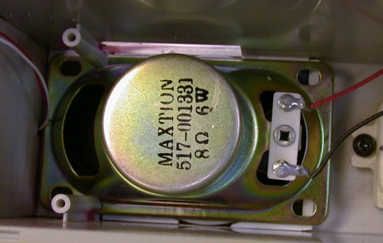 With the speaker
in place, it just fits in the selected area. The edges of the
speaker will be sealed to the fence and the walls with great globs
of hot glue.
With the speaker
in place, it just fits in the selected area. The edges of the
speaker will be sealed to the fence and the walls with great globs
of hot glue.
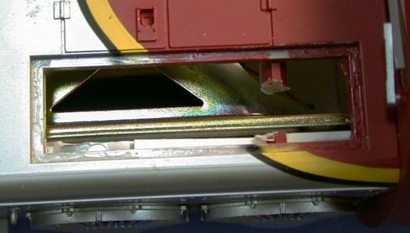 The speaker
fits nicely in the 1/4" section of the hood mounting post that was
hacked away.
The speaker
fits nicely in the 1/4" section of the hood mounting post that was
hacked away.
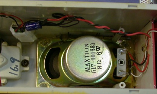 The DSX was stuck
to the side of the shell with double back tape and wired down to
the switch board through pin connectors. The speaker is sealed all
around with hot glue. There is just enough sound volume with the
DSX set to maximum volume. The hood is still vented to the outside
through the rear fans, but covering them up only changes to tone of
the sound slightly and doesn't impact the volume at all.
The DSX was stuck
to the side of the shell with double back tape and wired down to
the switch board through pin connectors. The speaker is sealed all
around with hot glue. There is just enough sound volume with the
DSX set to maximum volume. The hood is still vented to the outside
through the rear fans, but covering them up only changes to tone of
the sound slightly and doesn't impact the volume at all.
Eventually, I concluded that I wanted a little more audio power output than the DSX would provide so I added an "afterburner," a 5 watt audio power amplifier. Details are in my DSX Tips page.
[ Top ]
This is a highly detailed model with excellent mold work and equally excellent paint. However, there are some minor problems. Like most USA Trains products, the end user is required to install details such as handrails and such. Once these are added, the engine still fits in the Styrofoam inserts in its box. If you install Kadee couplers, some minor trimming of the Styrofoam inserts is necessary.
Most of the engine detail comes detached from the engine and must be user installed. Some of the parts, such as the eye bolts that hold on the cut levers, are small and not very sturdy. I managed to break a couple of the eyebolts during installation (or removal when I got one in the wrong hole). Some of the parts don't fit snugly in their mounting holes and needed a little drop of Zap-CA gap filler CA to hold them in place.
The instruction manual isn't completely clear as to where the parts go as the diagram isn't an accurate representation of the actual engine. The air hoses come in a left and right configuration and don't look like the picture in the manual. After I saw a photo of the PRR version in Model Railroader, I realized that I had installed them backwards. Then ends of the hoses should point inward so that they fit in the pockets in the end frames. The eyebolts for the cut levers go in the lower set of four holes. The handrails go in the upper set of four holes.
The handrails are all metal with metal stanchions. Some of the stanchions fit snugly in their holes and some don't. The end chains didn't hang well due to paint that had "glued" together some of the links. It was a small matter to break them apart again so that the chain would hang smoothly.
There is one handrail that fits across the end of the steps just above the cut lever that is not shown in the instructions.
The hanger straps on the trucks press on the side and hide the truck sideframe mounting screws. They don't fit in real snugly either, but you can't glue them in place because you'd have to break them off to access the screws if you ever needed to get the sideframe off.
On my GP9, the dynamic brake pods are just sitting on the top of the engine. If one should try to use them to pick up the engine, one might be in for a surprise when the engine drops to the floor. Don't use them for a handle.
The fans, 5 of them on my engine, all turn but they only freewheel. There is nothing to drive them except if you blow on them.
On various road names, the dynamic brake pods, and air tanks and other details are different. Check out the pictures at the USA Trains web site for details on what comes with each road name.
The Warbonnet version of the GP9 has a steam generator exhaust and vent port on the short hood so it qualifies to pull passenger cars. I don't know if these are on the other versions.
The cab doors open to reveal a moderately detailed cab interior. The engineer figure must be the twin of the one that drives the Aristo RS-3.
[ Top ]
 The wheels that come with the GP9 are
smaller than they should be (under 33") and they have a tendency to
pit and pack up with crud easily causing the engine to sputter
badly and require wheel cleaning much too often.
The wheels that come with the GP9 are
smaller than they should be (under 33") and they have a tendency to
pit and pack up with crud easily causing the engine to sputter
badly and require wheel cleaning much too often.
I installed these North West Short Line aftermarket wheels to see if they worked any better. These 40" wheels are considerably larger than the stock wheels and are made of solid nickel silver with steel axles. The wheels are not plated so that there can never be any plating problems.
This version of the wheels have a semifinescale flange so that the do not track as well on rough track as the stock wheels. They would be more suited to indoor layouts or for display. The larger wheels lift the engine off the track by about 0.1" so that now the strap hangers have respectable clearance to LGB turnout motors. They also lift the engine enough so that the sliders will not reach the track anymore so I removed them. There is insufficient clearance between the stock brake shoes to clear the larger wheels so some considerable grinding has be done to remove enough of the shoes to allow the wheels to fit.
Initially the wheels electrically performed quite well. I didn't run them as long as I would have liked because I got tired of rerailing the engine as it continually derailed on my less than perfect outdoor track. It is clear that the larger flange version will be required for outdoor usage. Even so, the wheels seemed to be starting to pit. The high copper content of nickel silver was apparently making itself known.
 I contacted NWSL about the derailment
difficulties of the finescale flange and they provided a
replacement set of 36" wheels with a larger flange. A 40" wheel
with a large flange just won't fit next to the brick. They had
these made special in stainless steel so I got a chance to try a
harder material too. The engine doesn't sit quite as high with the
36" wheels so that the track sliders do reach down to the
track.
I contacted NWSL about the derailment
difficulties of the finescale flange and they provided a
replacement set of 36" wheels with a larger flange. A 40" wheel
with a large flange just won't fit next to the brick. They had
these made special in stainless steel so I got a chance to try a
harder material too. The engine doesn't sit quite as high with the
36" wheels so that the track sliders do reach down to the
track.
These wheels seem to perform properly. The flange is large enough such that the engine had no derailment difficulties, and after about the same period of running (a half hour) that I had on the nickel silver wheels, there is no sign of pitting of the wheels. There was some discoloration but this appeared to be material from the track that was loosely adhering to the wheels. Where the treads scrubbed, the treads were clean.
The tractive effort of the loco did degrade with the new wheels,
see my Tractive
Effort Tips page for the details. The loss of four traction
tires does indeed reduce the traction of the engine. This loss can
be compensated with more weight. Just pressing on the top of the
engine a little while it was slipping caused it to grab and go. I
feel that the addition of 4 more points of power pickup more than
offsets the loss of the tires. Besides, the engine draws more
current than is good for it anyway, more traction just allows it to
draw more current and run hotter.
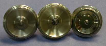 From the photo, it
is obvious how much bigger these wheels are and how much smaller
the flange of the 40 inch wheel is. The largest wheel is the nickel
silver wheel version, NWSL p/n 2522-6 at about $30 a set. The
middle sized wheel is the 36" stainless steel wheel version at
about $50 a set. The 36" wheel is available in nickel silver also.
The smallest wheel is the stock USA Trains wheel which works out to
just under 33 inches.
From the photo, it
is obvious how much bigger these wheels are and how much smaller
the flange of the 40 inch wheel is. The largest wheel is the nickel
silver wheel version, NWSL p/n 2522-6 at about $30 a set. The
middle sized wheel is the 36" stainless steel wheel version at
about $50 a set. The 36" wheel is available in nickel silver also.
The smallest wheel is the stock USA Trains wheel which works out to
just under 33 inches.
The wheels come as 8 half axles. The old wheels have to be pulled from the plastic drive gear, the bushings removed and reassembled with the new half axles. The new wheels do not come grooved for a traction tire.
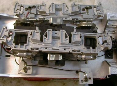 Replacement of the wheels requires the removal and replacement of
40 screws so it takes some time. However, the wheels come with an
excellent set of instructions so the work not difficult or
confusing. This photo shows one sideframe after the axle journals
have been removed and the other with the journals still in
place.
Replacement of the wheels requires the removal and replacement of
40 screws so it takes some time. However, the wheels come with an
excellent set of instructions so the work not difficult or
confusing. This photo shows one sideframe after the axle journals
have been removed and the other with the journals still in
place.
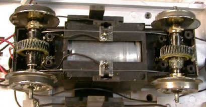 This is the brick after both sideframes and the
bottom cover has been removed. Notice how big the motor is. This is
a high current motor which is one reason why this engine pits its
wheels so badly. The stock wheel at the upper right is so badly
pitted that it looks like it has a traction tire.
This is the brick after both sideframes and the
bottom cover has been removed. Notice how big the motor is. This is
a high current motor which is one reason why this engine pits its
wheels so badly. The stock wheel at the upper right is so badly
pitted that it looks like it has a traction tire.
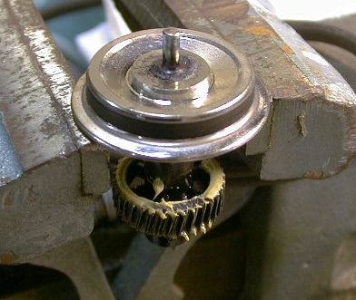 Pulling the wheels and gears apart can be a challenge. NWSL
recommends their gear puller, but since I didn't have one, I
improvised. If the axle assembly is hung from the open jaws of a
bench vice, the other wheel can be pressed straight downward until
it pops off. The gear can be pressed downward also but it is small
such that the teeth dug into my thumbs enough to make it quite
painful. I opened the jaws of a large pair of needle nose pliers
around the axle above the gear and pressed on the jaws to press off
the gear.
Pulling the wheels and gears apart can be a challenge. NWSL
recommends their gear puller, but since I didn't have one, I
improvised. If the axle assembly is hung from the open jaws of a
bench vice, the other wheel can be pressed straight downward until
it pops off. The gear can be pressed downward also but it is small
such that the teeth dug into my thumbs enough to make it quite
painful. I opened the jaws of a large pair of needle nose pliers
around the axle above the gear and pressed on the jaws to press off
the gear.
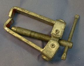 The bushings can usually be pulled off with a
pair of gas pliers, but two of them wouldn't come off without the
use of this gear puller. The bushings pressed back on the new axles
with no difficulty. The drive gear needs to be well centered on the
half axles. An dial caliper comes in really handy in setting the
0.685" spacing required between the edge of the gear and the wheel
back. When properly set, the back to back spacing of the wheels is
the recommended 1.600". The stainless set has a much thicker
flange, so its back to back spacing is less. Mine are set at 1.500"
to 1.525"
The bushings can usually be pulled off with a
pair of gas pliers, but two of them wouldn't come off without the
use of this gear puller. The bushings pressed back on the new axles
with no difficulty. The drive gear needs to be well centered on the
half axles. An dial caliper comes in really handy in setting the
0.685" spacing required between the edge of the gear and the wheel
back. When properly set, the back to back spacing of the wheels is
the recommended 1.600". The stainless set has a much thicker
flange, so its back to back spacing is less. Mine are set at 1.500"
to 1.525"
[ Top ]
The GP9 is fairly easy to get into, although there are a lot of screws that need to be removed. Since disassembly of any engine will usually result in some rough handling, it is a good idea to remove the easy to break details first. On the GP9, the handrails MUST come off. Pull them out of the mountings and set them aside.
The body comes off more or less as a solid unit. There are four shorter screws that secure the walkways. These are visible underneath the frame surrounding the cab. Two additional screws retain the fuel tank, but it is not necessary to remove the tank to get inside the engine. Eight more longer screws are recessed about 2" up inside raised posts. There are actually twelve posts, four around each truck and four more near the center. However, only eight of these were actually used. You'll need a long #1 Phillips screwdriver to get to these screws. I used the same 6" long #1 power screwdriver bit that I used to get at the roof screws on Aristo Heavyweights. This tool was a little hard to find, I had to go to a speciality tool store.
Once all these screws are removed, recovered and stored, lift the entire body off as a unit. One of the running board assemblies will come off by itself. The other is part of the cab. The cab can then be slid out of the body shell for access to the cab interior.
Reassembly is pretty direct but there is one major caution. If the body won't go all the way back on, DO NOT force it. One of the wires is probably hung between the frame and hood mounting posts. If you force the hood down, you'll shear the wire. It may take several attempts, but the hood will go back on without force.
[ Top ]
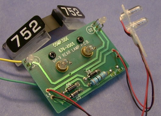 The GP9 uses
incandescent bulbs for both the number boards and headlights. The
markers are bi-color red/green LEDs. The boards and lights can be
easily removed for service or modification. Two screws hold in the
board assembly. A weak adhesive holds in the marker panels. It
doesn't take much pressure to break the bond. Then the panels can
be pushed out. The allows the headlight assembly to then be pushed
out.
The GP9 uses
incandescent bulbs for both the number boards and headlights. The
markers are bi-color red/green LEDs. The boards and lights can be
easily removed for service or modification. Two screws hold in the
board assembly. A weak adhesive holds in the marker panels. It
doesn't take much pressure to break the bond. Then the panels can
be pushed out. The allows the headlight assembly to then be pushed
out.
 The
boards have a different layout, but are essentially the same
schematically. The headlight steering diode (D7 or D8) is reversed
between the two boards. The actual LEDs (D1 and D2) are also
flipped to exchanged red for green.
The
boards have a different layout, but are essentially the same
schematically. The headlight steering diode (D7 or D8) is reversed
between the two boards. The actual LEDs (D1 and D2) are also
flipped to exchanged red for green.
The boards are wired in parallel on the main circuit board so that the "red" input on one board is connected to the "red" input on the other board. The "black" inputs are similarly connected. The actual wire colors may vary, refer to the markings on the boards themselves.
Conversion of the lighting to DCC or radio control will require some significant changes to the boards if constant intensity is desired.
If constant intensity is not required, then wire the boards to the motor circuit of the decoder or receiver and at least the directionality will be retained without the need to modify the boards.
At 20 volts DC in to the board, the number board lamps draw about 115 mA, the headlights about 75 mA and the markers 55 mA for a total of 245 mA.
DCC lighting conversion cannot be done with the type of bicolor LED used by USA Trains. The LED type is commonly called a "common cathode" type in that the "negative" terminal is common. The type needed for a DCC conversion is a "common anode" type so that the common terminal can be connected to the DCC decoder blue wire and the other terminals can be connected through limiting resistors to the function outputs of a decoder. Common anode bi-color LEDs are available but are harder to find than the common cathode type. Further, a lot of board traces would require hacking and a new 3 wire harness wired to connect the markers and headlights.
 This
schematic shows what you would need to do to retain the
functionality of the existing lighting. You could also change out
the incandescent bulbs for white LEDs as well. The original
lighting switch will not control the headlights and markers, all
this would be handled through the DCC decoder. The original
lighting switch would then only control the cab light.
This
schematic shows what you would need to do to retain the
functionality of the existing lighting. You could also change out
the incandescent bulbs for white LEDs as well. The original
lighting switch will not control the headlights and markers, all
this would be handled through the DCC decoder. The original
lighting switch would then only control the cab light.
By comparing this schematic to the one above, you can see that there isn't much left of the original circuit. The two wire harness becomes four wires, the original bi-color LEDs are changed out. The steering diodes (3) are abandoned and the current limiting resistor value is changed and split into two resistors. If you couldn't find a common anode bicolor LED, it might be just as well to just forget the green part and use a regular red LED that would illuminate to the rear only. If you use just a red LED, you can wire the diodes in series and use only one 1000 ohm current limiting resistor. This saves 20 mA.
The function of the red/green markers is pretty much in doubt anyway. The red markers would only be used for light moves or when the engine was used as a pusher. The green light to the front would only be used for particular train classes. Red lights on the front of a train that is backing would never be turned on.
 I
looked around at local parts stores for the common anode bi-color
(sometimes called tri-color because if you light both the red and
green diodes, it glows amber too) LED and I couldn't find one. So I
choose to just use a red marker. I wanted to change out the
headlights to white LEDs and change the markers to dimmer bulbs as
well. Since this circuit didn't use ANY of the original parts and I
would have had to completely hack up the stock board to rewire it,
I elected to make my own boards instead. It was pretty easy, the
only part I reused was the metal bracket. The LEDs are wired in
series to minimize current draw and I ran the number boards to a
separate decoder function so that I could control their operation
through command mapping.
I
looked around at local parts stores for the common anode bi-color
(sometimes called tri-color because if you light both the red and
green diodes, it glows amber too) LED and I couldn't find one. So I
choose to just use a red marker. I wanted to change out the
headlights to white LEDs and change the markers to dimmer bulbs as
well. Since this circuit didn't use ANY of the original parts and I
would have had to completely hack up the stock board to rewire it,
I elected to make my own boards instead. It was pretty easy, the
only part I reused was the metal bracket. The LEDs are wired in
series to minimize current draw and I ran the number boards to a
separate decoder function so that I could control their operation
through command mapping.
 This is the
homebrew board. It is made on 0.050" center perforated board cut to
size. The parts leads are just inserted in the board and soldered
together on the other side. The 4 wire harness wasn't installed
when this photo was taken.
This is the
homebrew board. It is made on 0.050" center perforated board cut to
size. The parts leads are just inserted in the board and soldered
together on the other side. The 4 wire harness wasn't installed
when this photo was taken.
 The
board fits right back where the original was. The number board
holds the headlights in place and the board itself holds the number
boards in place.
The
board fits right back where the original was. The number board
holds the headlights in place and the board itself holds the number
boards in place.
Later a 5 wire harness was built to connect to both the front and rear boards. A 5 pin connector was installed in the harness to allow the hood assembly to be disconnected from the frame were the decoder is. The 5 wires are:
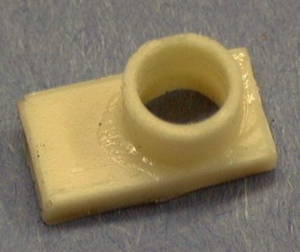 Since the DCC
decoder that I installed (see below) has ditch light capability, I
elected to install some. I made a small pattern that will hold a 5
mm LED and made a mold so that I could cast the ditch light
housings in resin. This item looks sort of like ditch light
housings that I've been able to spot in photos of ATSF SD45's.
Since the DCC
decoder that I installed (see below) has ditch light capability, I
elected to install some. I made a small pattern that will hold a 5
mm LED and made a mold so that I could cast the ditch light
housings in resin. This item looks sort of like ditch light
housings that I've been able to spot in photos of ATSF SD45's.
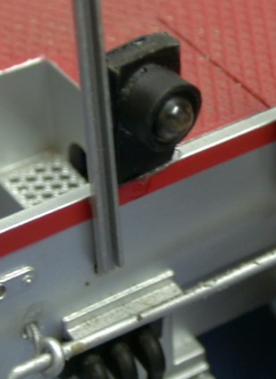 When painted and glued
to the pilot of the GP9, the ersatz ditch lights don't look half
bad. I ran the wires down under the steps and up holes drilled in
the floor. With a 1K ohm resistor in series, they can be connected
directly to some unused function outputs of the NCE D808 decoder. A
little bit of programming sets them to be all on with the headlight
and flash alternately for 5 seconds following the last horn
signal.
When painted and glued
to the pilot of the GP9, the ersatz ditch lights don't look half
bad. I ran the wires down under the steps and up holes drilled in
the floor. With a 1K ohm resistor in series, they can be connected
directly to some unused function outputs of the NCE D808 decoder. A
little bit of programming sets them to be all on with the headlight
and flash alternately for 5 seconds following the last horn
signal.
[ Top ]
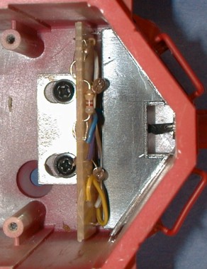
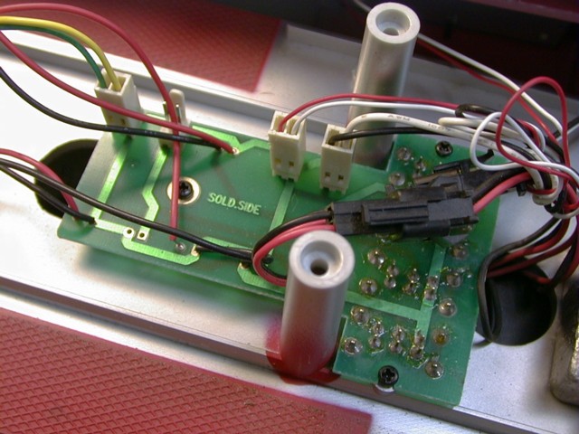 All of the major
interconnections in the GP9 are one on a switch circuit board. The
switches poke through the frame near the front truck. The power
pickups, motors, lighting boards, cab light, and smoke unit are
plugged into this board. There is also a connection for an add-on
sound system.
All of the major
interconnections in the GP9 are one on a switch circuit board. The
switches poke through the frame near the front truck. The power
pickups, motors, lighting boards, cab light, and smoke unit are
plugged into this board. There is also a connection for an add-on
sound system.
 The
interconnections are pretty straightforward. All of the loads and
one pair of pickups are bussed together on the board. The other set
of pickups and all four switches are connected. Each switch is
routed to its respective load.
The
interconnections are pretty straightforward. All of the loads and
one pair of pickups are bussed together on the board. The other set
of pickups and all four switches are connected. Each switch is
routed to its respective load.
The easiest method to install a DCC decoder or track powered receiver will be to unsolder all four motor wires and reconnect them back to the the motor output of the motor controller. The power input to the controller would then hook back to one of the motor terminals. The lighting will stop working correctly though. With DCC, all the lights will come on all the time. With constant DC on the track, the lights may or may not correspond to the engine direction. Modifications necessary to get the lighting to work properly are substantial as described in the previous section.
[ Top ]
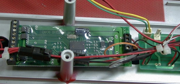 I've had this loco for four years until
before I'd ever been inside. This is because I realized that the
GP9 was not a candidate for DCC installation because no available
decoder would handle the very high stall current of the USA Trains
locos. However, NCE has just come out with a very beefy decoder
especially designed for the USA Trains Locos. The D808 has an
average current rating of 8 amps and a stall current rating of 30
amps.
I've had this loco for four years until
before I'd ever been inside. This is because I realized that the
GP9 was not a candidate for DCC installation because no available
decoder would handle the very high stall current of the USA Trains
locos. However, NCE has just come out with a very beefy decoder
especially designed for the USA Trains Locos. The D808 has an
average current rating of 8 amps and a stall current rating of 30
amps.
The D808 can be easily placed aft of the switch board. It is just a little bit too wide to fit between the hood mounting posts, but a few seconds of file work on the posts makes enough room. The decoder is secured to the frame with a small piece of Velcro.
I've really tried to blow up this decoder but I've been unsuccessful. I dragged as many cars as the loco would handle without wheel slip and the decoder barely got warm. I pressed the loco into the track at full speed until the AC ammeter on my power supply pegged at 10 amps and neither the NCE PB110 booster or the decoder shut down. I couldn't actually stall the loco due to the very high torque. I didn't abuse it this way for very long as I was more afraid of stripping gears or burning up the motors than burning up the decoder.
 For the motor
connections, I just unsoldered all four motor wires from the switch
board and wired them together (red to black because the trucks are
reversed with respect to each other) then to the motor terminals of
the decoder. The power terminals of the decoder are wired back to
the terminals on the switch board that used to go to the rear
motor. This way, the motor switch can disconnect the D808 to allow
programming of the DSX. I left the smoke wired directly to the
track through its own switch. The front and rear lighting has been
completely redone and is all wired through the D808. The cab light
is still wired through the original lighting switch.
For the motor
connections, I just unsoldered all four motor wires from the switch
board and wired them together (red to black because the trucks are
reversed with respect to each other) then to the motor terminals of
the decoder. The power terminals of the decoder are wired back to
the terminals on the switch board that used to go to the rear
motor. This way, the motor switch can disconnect the D808 to allow
programming of the DSX. I left the smoke wired directly to the
track through its own switch. The front and rear lighting has been
completely redone and is all wired through the D808. The cab light
is still wired through the original lighting switch.
The DSX is wired to the sound pins on the switch board so that it can be turned off with the sound switch while programming the D808.
Since all the loads in the loco are wired through the switch bank, it is no problem to run two decoders. During programming, the cab lights, smoke and the other decoder will be turned off so that the remaining decoder will work properly on the programming track.
It's probably of no interest to anybody but me but the function controls on the GP9 are:
| Function Number |
Which Decoder |
Which Output(s) |
Function |
|---|---|---|---|
| F0 | D808 | 1 | Front Headlights |
| F0 | D808 | 2 | Rear Headlights |
| F0 | D808 | 5 | Left Ditch Light |
| F0 | D808 | 6 | Right Ditch Light |
| F1 | DSX | n/a | Bell |
| F2 | DSX | n/a | Horn |
| F3 | DSX | n/a | Coupler Clank |
| F4 | DSX | n/a | Dynamic Brake |
| F5 | D808 | 7 | Front Number Board |
| F6 | D808 | 8 | Rear Number board |
| F7 | n/a | n/a | n/a |
| F8 | DSX | n/a | Sound Off |
After I got it all back together, the cab light was entirely too bright for the constant 23 v rms of DCC power that I have on my track. A 220 ohm 1/2 watt resistor wired in series with one of the cab light wires fixed that in a hurry.
I had been suffering wheel pitting, even with the aftermarket stainless steel wheels, since I installed DCC in this loco. DCC itself wasn't the problem because other DCC locos don't pit their wheels. The problem is that I have a very high current capability on this layout and a loco that wants and can draw lots of current. This combination of loco and environment has crossed the line into troubled territory.
I had written a description of what was going on here but I decided to move it to its own page because the problem can actually occur on a wider range of locos than just this USAT loco.
This page has been accessed times since 29 May 1998.
© 1998-2011 George Schreyer
Created 29 May 1998
Last Updated October 28, 2011