 7 May 10 7 May 10
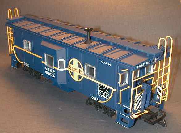
USA Trains has finally released their bay window caboose. There is also a wide vision version. The caboose comes with internal lighting, a flashing red light to the rear and metal wheels. There is no internal detail. Hook and loop couplers are installed, a pair of USA knuckles are provided.
Power is picked up on two axles with carbon type brushes.
[ Top ]
Overall, the paint and details on the model are excellent, right down to the no-slip grid on the end platforms. Unlike most other USA products, all the detail comes attached.
All the hand rails, guard rails and ladders are metal wire. The downside is that the wires are soldered to form the desired structures and some of the solder joints are not too well made. One of the ladders literally fell apart in my hands while I was removing the roof to install a battery.
[ Top ]
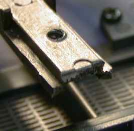 A Kadee #831 truck
mounted coupler is fairly easy to attach to the caboose. The
supplied hook and loops are removed with one screw. To properly fit
the Kadee, the end of the coupler tang should be cut off right
through the middle of a circular mold mark near the end of the
tang. The Kadee will then screw right on with the screw that held
on the hook and loop. The height will come out just right and the
car to car spacing to other cars will be acceptable as well.
A Kadee #831 truck
mounted coupler is fairly easy to attach to the caboose. The
supplied hook and loops are removed with one screw. To properly fit
the Kadee, the end of the coupler tang should be cut off right
through the middle of a circular mold mark near the end of the
tang. The Kadee will then screw right on with the screw that held
on the hook and loop. The height will come out just right and the
car to car spacing to other cars will be acceptable as well.
[ Top ]
 The
lighting on the caboose needed a little work. The interior lights
are much too bright when powered from DCC on the track. To gain
access to the lights, the roof must be removed.
The
lighting on the caboose needed a little work. The interior lights
are much too bright when powered from DCC on the track. To gain
access to the lights, the roof must be removed.
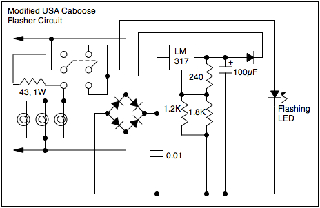
 This is
the schematic of the lighting circuit. The interior lights run
directly from the track. There are three bulbs that really want to
run about 10 volts for reasonable brightness. I added two 43 ohm 1
watt resistors in series with the lights to tone them down. Setting
the switch to "rear lights on" dims the interior lights.
This is
the schematic of the lighting circuit. The interior lights run
directly from the track. There are three bulbs that really want to
run about 10 volts for reasonable brightness. I added two 43 ohm 1
watt resistors in series with the lights to tone them down. Setting
the switch to "rear lights on" dims the interior lights.
All the circuitry on the board drives the flashing rear light. The circuit is designed to flash when there is track voltage. If a 9 volt rechargeable battery is installed, the light will come on with constant intensity when there is no track voltage.
Eventually, my flasher circuit failed to flash. I have figured out how the circuit is SUPPOSED to work, but it just doesn't do it.
The 51 ohm resistor senses the current in the LED, when the current gets high (about 19 mA), the voltage drop across the resistor turns on the transistor which shuts down the LM317 regulator. The 100 uF capacitor discharges through the LED and the LED current decreases. Eventually, the transistor shuts off and the regulator comes back on, increasing the LED current.
Mine just sat there at partial intensity and since I couldn't get it to work, I just disabled the feedback loop by shorting the 51 ohm resistor. This caused the LED to come back on with reasonable intensity.
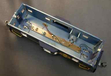
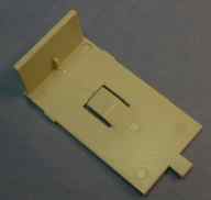 Once the roof is off, the battery cover can be released by pushing
on the clip under the floor. However, the cover wouldn't fit back
over the battery and clip down. I had to trim about half of the
little tab spacer at the corner in the cover to allow the clip to
engage.
Once the roof is off, the battery cover can be released by pushing
on the clip under the floor. However, the cover wouldn't fit back
over the battery and clip down. I had to trim about half of the
little tab spacer at the corner in the cover to allow the clip to
engage.
Since I converted my layout to DCC and the track voltage is constant anyway, I eventually dispensed with the battery altogether.
 Fast
forward about 10 years and I finally got the flasher to work by
essentially gutting the circuit and using a flashing LED (All
Electronics LED-4).
Fast
forward about 10 years and I finally got the flasher to work by
essentially gutting the circuit and using a flashing LED (All
Electronics LED-4).
This particular flashing LED wants to run from 3 to 5 volts with no current limiting resistor, it sets it's own current at about 10 mA while it's on. I have removed all the unnecessary parts from the schematic, but there is no need to actually remove them from the board. The 51Ω and 470Ω resistors can simply be shorted out. The new 1.2KΩ resistor is wired in parallel with the existing 1.8KΩ resistor. I added a new 0.01µF capacitor just for insurance to keep the regulator stable. These changes turn the regulator circuit into a 4.5 volt or so constant voltage that can directly drive the flashing LED. The battery should not be used so that this mod doesn't work for DC track power, the LED won't continue to flash once the track voltage drops below 6 volts or so.
I also removed one of the 43 ohm resistors used to dim the ceiling lights, they were just too dim.
[ Top ]
This page has been accessed times since 6 Nov 1999.
© 1999-2010 George Schreyer
Created Nov 6, 1999
Last Updated May 7, 2010