 6 Feb 08
 14 Sep 075 Feb 085 Feb 08
I have experienced some considerable difficulties with LGB 1600 and 1200 turnouts which I believe are generic to their design. This page describes what I have done to fix these difficulties.
6 Feb 0814 Sep 075 Feb 085 Feb 08I found that the pivot screws under the point rails on 1600 series turnouts to be loose on almost every turnout that I had. Of course, I discovered this after the screws fell out and I had to pull the turnouts to recover and reinstall the screws.
There is an easy fix. Before you install a turnout, Loctite the screw in place. There are many flavors of Loctite. Only type 222 is especially rated for set screws and it is the ONLY kind that should be used. All of the other types emphasize the "tite" part and if you use them, you'll never get the screw back out if you should ever need to.
[ Top ]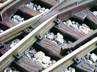 I found that derailments were common
with these turnouts when pushing a cut facing point through the curved
path of the turnout. The problem is that the curved point rail is
gauged way too wide. When a car is pushed, its wheels tend to move to
the outside rail (the point rail in this case). When the other wheel,
the one on the stock rail, gets to the guard rail, it hits the guard
rail. This is supposed to kick the wheel back in place and sometimes it
does. However after the soft plastic guard rail gets whacked by a
couple of hundred wheel flanges, it gets all dinged up as shown in the
photo. The wheel then hangs up on the shredded plastic and cannot slide
on the guard rail. Instead, it pops over the guard rail and a
derailment occurs.
I found that derailments were common
with these turnouts when pushing a cut facing point through the curved
path of the turnout. The problem is that the curved point rail is
gauged way too wide. When a car is pushed, its wheels tend to move to
the outside rail (the point rail in this case). When the other wheel,
the one on the stock rail, gets to the guard rail, it hits the guard
rail. This is supposed to kick the wheel back in place and sometimes it
does. However after the soft plastic guard rail gets whacked by a
couple of hundred wheel flanges, it gets all dinged up as shown in the
photo. The wheel then hangs up on the shredded plastic and cannot slide
on the guard rail. Instead, it pops over the guard rail and a
derailment occurs.
Several attempts at refacing the guard rail proved fruitless. The only course of action was to fix the problem at its source. The turnouts need regauging so that the wheel on the stock rail actually slips inside the guard rail without actually touching it. The guard rail is there to keep the wheel in the frog in line so that it will pass through the frog. The tapered end on the guard rail should NEVER be required to properly align a wheel.
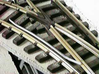
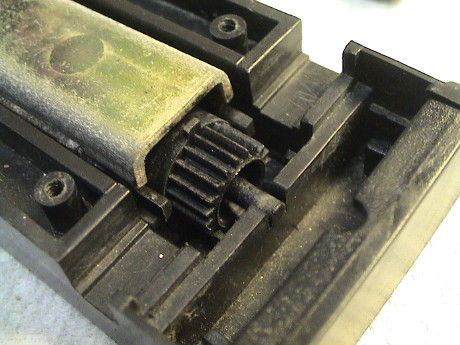
Since moving the point rail looked like it would be very difficult, I instead elected to widen the inside edge of the rail to narrow the gauge. I did this by soldering a 1/32" thick piece of 1/8" to 3/32" wide brass strip stock to the inside of the point rail. This turned out to be actually pretty easy. My Track Soldering Tips Page has instructions you can use to solder the strips. You only need to solder the strips in a couple of spots each. If you look near the frog in the photo above you'll see the added strip. It is trimmed and bent so that if fits right into the frog assembly.
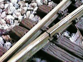 The strip extends down the length of the
point rail to the gap between the fixed and moving parts of the point
rail. From there another piece extends down to the point.
The strip extends down the length of the
point rail to the gap between the fixed and moving parts of the point
rail. From there another piece extends down to the point.
 The point end is trimmed and filed to allow unimpeded
wheel passage. I've cut mine about 1/2" short of the existing point. I
run a wheelset through the point by hand while twisting and pressing
every which way to make sure that the wheel will pass without even
feeling the new piece of brass. If the wheel catches anything at all,
the point has to be worked over with a grinding tool or file until the
wheel can slide through the point like it was a piece of straight (or
curved) rail. The gap in the point rail needs to be checked the same
way.
The point end is trimmed and filed to allow unimpeded
wheel passage. I've cut mine about 1/2" short of the existing point. I
run a wheelset through the point by hand while twisting and pressing
every which way to make sure that the wheel will pass without even
feeling the new piece of brass. If the wheel catches anything at all,
the point has to be worked over with a grinding tool or file until the
wheel can slide through the point like it was a piece of straight (or
curved) rail. The gap in the point rail needs to be checked the same
way.
Since I've installed this modification on almost every one of my turnouts, derailments are rare.
Even without this modification, almost every LGB turnout needs point work. The point should be worked over with a small file or motor tool grinding wheel so that a wheelset can be pushed through the point without even feeling it.
If you have metal wheels and you hear clicks when your cars are going through turnouts, the turnouts need work. Any wheel noise should be subdued. If not, it indicates that a flange is striking something or a wheel is lifting off the rail and dropping back down. Plastic wheels tend to deaden noise and you may not hear problems as well. Listen very carefully as you drag AND push a train through each and every turnout in both directions and with the turnout set each way. Any unusual click should be investigated and eliminated. There will be soft clicks as the wheels go through the frog even on a perfect turnout, problems are indicated by louder clicks or clicks caused by wheels at the points or the point rail gap. Listen carefully and you'll soon be able to tell the difference.
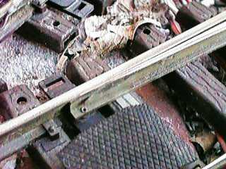
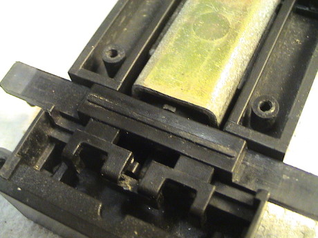
 Todd Brody found that he could
reface a damaged plastic guard rail by bending a 1/64" thick by 3/32"
wide brass strip around it as shown in the photo. He found specific
instances where this improved tracking. This does get rid of the glue problem and the piece is completely reversible.
Note that brass strip is usually die cut such that the edges on one
side are rounded and the edges on the other side are sharper. The
rounded edge should be the one facing the wheels.
Todd Brody found that he could
reface a damaged plastic guard rail by bending a 1/64" thick by 3/32"
wide brass strip around it as shown in the photo. He found specific
instances where this improved tracking. This does get rid of the glue problem and the piece is completely reversible.
Note that brass strip is usually die cut such that the edges on one
side are rounded and the edges on the other side are sharper. The
rounded edge should be the one facing the wheels.
I've used this trick in one specific place where a particular car would derail trailing point from the diverging route every time. This was my Aristo Streamliner Track Cleaning Car which places very large torsion forces on the trucks. The lead wheel set would derail in the frog every time until the guard rail was tightened to bring the wheel back into line through the whole frog. I placed a 0.015" x 0.200" styrene shim behind the brass strip to tighten it up just a little more. Now the car gets through that turnout without derailing every time.
I have had less difficulty with LGB 1200 series (tight radius) turnouts, but I still had derailment problems on some turnouts. In this case, the gauge on the curved section is too tight on some but not all units. I believe that this is due to the way that the point rail was bent during manufacture.
The impact of the problem is different, but the result is the same, derailments. When the gauge is too tight, a wheel tends to slip across the frog within the gap then hits the point of the frog straight on and pops over the frog. It appeared that just grinding on the frog would probably make the problem worse, so the solution had to be at the other wheel.
 The gap between
the guard rail and the stock rail is too large which allows the wheel
at the frog to drift into the frog. I glue a 20 to 30 mil styrene or
brass strip inside the guard rail to tighten up the spacing. This pulls
the wheel on the stock rail over tighter against the stock rail and
tends to allow the other wheel to barely slip past the frog. This
solution has been effective as long as the added strip stays attached
to the guard rail. As discussed below in The Impact of
Adhesives on Tie Strips, few adhesives stick well to LGB tie
strips.
The gap between
the guard rail and the stock rail is too large which allows the wheel
at the frog to drift into the frog. I glue a 20 to 30 mil styrene or
brass strip inside the guard rail to tighten up the spacing. This pulls
the wheel on the stock rail over tighter against the stock rail and
tends to allow the other wheel to barely slip past the frog. This
solution has been effective as long as the added strip stays attached
to the guard rail. As discussed below in The Impact of
Adhesives on Tie Strips, few adhesives stick well to LGB tie
strips.
This modification is not necessary on every turnout, and on some you may have to tweak the strip thickness. If you use too thick a strip, an underguage wheelset will bind between the guard rails on the stock rail and the frog which will cause derailments just as bad as having too thin a strip.
I have had some difficulties with LGB 1200 turnouts and the San-Val Little Wheelie Worker track cleaner attachment. The disks will hang up on the end of the point rails when moving trailing point. The solution is to break the corner at the end of the point rail with a fine file to allow the disks to slip over the end of the point rail.
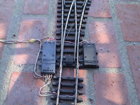
The point rails of both the LGB 1200 and 1600 series turnouts are electrically connected to their associated stock rail by three methods providing triple redundancy. The point rails rest against a stock rail (sometimes), they ride on a metal slider strip (unless the strip gets cruddy which it does) and they pivot on a screw that has a contact wiper under its head. However, when the turnouts are used outside, this is still not good enough to provide 100% reliability.
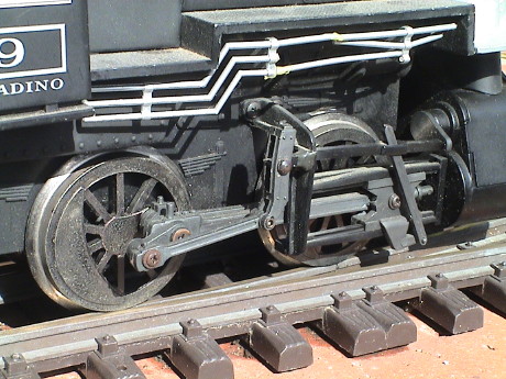 I still have troubles with a point rail
going dead. For example, this Aristo 0-4-0 has a wheelbase short enough
so that both drivers can rest on the moving part of the point rail. The
loco was backed slowly onto this turnout and it stopped dead just as
soon as the lead driver crossed the gap between the moving and fixed
point rails. After 12 years on the layout, EVERY turnout on the layout
became a dead stop for this loco.
I still have troubles with a point rail
going dead. For example, this Aristo 0-4-0 has a wheelbase short enough
so that both drivers can rest on the moving part of the point rail. The
loco was backed slowly onto this turnout and it stopped dead just as
soon as the lead driver crossed the gap between the moving and fixed
point rails. After 12 years on the layout, EVERY turnout on the layout
became a dead stop for this loco.
The easiest and quickest remedy is to grab the point rail and move it back and forth while somewhat forcefully pressing it down onto the contact strip near the point to scrape off the crud that collects on the contact strip. This works in the short term, but it does wear the contract strip faster and it will eventually wear out.
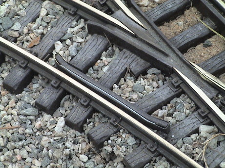
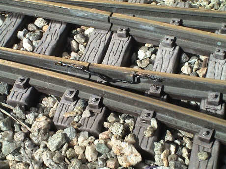 I've had so much of this trouble that I've
soldered a small flexible wire jumper between the point rail and its
stock rail on both point rails on ALL my turnouts. If a black wire is
used, it can be hidden well enough so that it won't be seen unless
someone looks for it.
I've had so much of this trouble that I've
soldered a small flexible wire jumper between the point rail and its
stock rail on both point rails on ALL my turnouts. If a black wire is
used, it can be hidden well enough so that it won't be seen unless
someone looks for it.
The Weller 250 watt soldering gun is a little big and clumsy to use in this area. My soldering station has enough heat to do this job because the rails being soldered are short and not well heat sunk. I picked a sunny morning with no breeze and went to work. I used the 0-4-0 for testing. Before I started, it would stall on each of the seven turnouts in the yard. When I was done in the yard, there was no problem at all. Eventually, I soldered all of the turnouts on the layout.
 LGB turnout
motors have no brushes and only two moving parts so they are usually
pretty reliable. However, when they fill with water, they get pretty
cruddy inside. The cover is designed to exclude water from entry from
above and most of the time that works. However, sometimes a motor will
leak through the screw holes for the wire terminals. This leakage can
be prevented simply by leaving a bead of hot glue on top of the motor.
If access is needed to the screws, the hot glue plug can be simply
peeled off.
LGB turnout
motors have no brushes and only two moving parts so they are usually
pretty reliable. However, when they fill with water, they get pretty
cruddy inside. The cover is designed to exclude water from entry from
above and most of the time that works. However, sometimes a motor will
leak through the screw holes for the wire terminals. This leakage can
be prevented simply by leaving a bead of hot glue on top of the motor.
If access is needed to the screws, the hot glue plug can be simply
peeled off.
If your motors are installed in areas where water rises above the openings in the side of the housings and floods the interior, you might want to consider drilling a drain hole in the bottom of the housing. This will let water in sooner, but it will let it out much quicker as well.
Sometimes a turnout motor will stall before it completes its transition. If a motor stalls, it'll usually complain by buzzing. If the motor buzzes while it moves, its on the edge of a stall. It should snap to its new position very abruptly. There are several common causes of motor stalling.
 Sometimes all of the above is just not
enough. This turnout had been giving me problems for years. I had even
bumped the power supply to all the turnouts on the layout to about 32
volts. Under the best conditions, it would just barely make it most of
the time. However, the few times that it didn't make it all the way
over was a real problem because this turnout controlled the reversing
function of a wye and when it went partially over and a train entered
the wye from the wrong direction, it would cause a short. I finally
gave up and installed a 2nd motor on this turnout and wired the motor
in parallel with the original motor. Now it snaps REALLY smartly. I
don't expect any more trouble from this turnout. This solution is sort
of expensive and it requires enough room on the other side of the
turnout but it works.
Sometimes all of the above is just not
enough. This turnout had been giving me problems for years. I had even
bumped the power supply to all the turnouts on the layout to about 32
volts. Under the best conditions, it would just barely make it most of
the time. However, the few times that it didn't make it all the way
over was a real problem because this turnout controlled the reversing
function of a wye and when it went partially over and a train entered
the wye from the wrong direction, it would cause a short. I finally
gave up and installed a 2nd motor on this turnout and wired the motor
in parallel with the original motor. Now it snaps REALLY smartly. I
don't expect any more trouble from this turnout. This solution is sort
of expensive and it requires enough room on the other side of the
turnout but it works.
If a turnout motor stalls, it can be tempting to power the motor from a DC source instead of a rectified AC source. They will snap over smartly when run from DC but DON'T DO IT! Running the motors from DC will provide over twice the torque at any given voltage, but it also puts the motors at extreme risk of burnout. It will take only a few seconds with DC applied to silently toast an LGB turnout motor. The motors will take half wave rectified AC for quite awhile and they will buzz loudly the whole time providing an audible signal that something is wrong. The inductance of the motor windings provides natural current limiting that helps keep the current that the motors draw under some form of control. With DC, the only current limiting is the resistance of motor and wiring which is not high enough to limit the current to safe values.
If you insist on using DC, then provide some form of time limited triggered current pulses via custom driver circuitry. Pulse systems provide this limited energy pulse. These are safe for use on LGB motors. However, LGB motors require bi-polar pulses and most existing pulse systems won't produce pulses of either polarity. The Aristo ART-5475, however, is designed with bipolar outputs and each output of the five outputs will drive one LGB motor quite nicely.
[ Top ]Every year or so, you'll probably have to pop the cover on most of your motors and clean them out. Even one piece of sand in the throwbar channel can bind up a motor. The maintenance procedure is easy, just follow the steps below
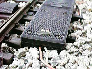
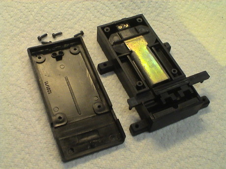 These photos show some of the steps
described above. This motor had been outside for 12 years when the
photo was taken and was in pretty good shape considering that it
possibly had not been maintained in all that time. The motor consists
of a single coil of wire that magnetizes two steel pole pieces. A
permanent magnet is mounted in a rotor between the pole pieces and
drives a gear that engages a rack on the bottom of the throwbar. The
motor rotation is limited by a small tab on the gear that stops against
a plastic stop on each side of the pole piece.
These photos show some of the steps
described above. This motor had been outside for 12 years when the
photo was taken and was in pretty good shape considering that it
possibly had not been maintained in all that time. The motor consists
of a single coil of wire that magnetizes two steel pole pieces. A
permanent magnet is mounted in a rotor between the pole pieces and
drives a gear that engages a rack on the bottom of the throwbar. The
motor rotation is limited by a small tab on the gear that stops against
a plastic stop on each side of the pole piece.
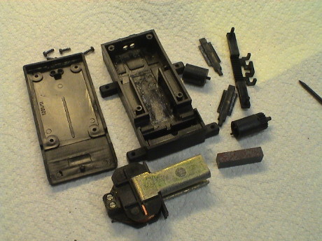 This is the
motor fully disassembled. In order to properly clean it out, it has to
be taken apart this far.
This is the
motor fully disassembled. In order to properly clean it out, it has to
be taken apart this far.
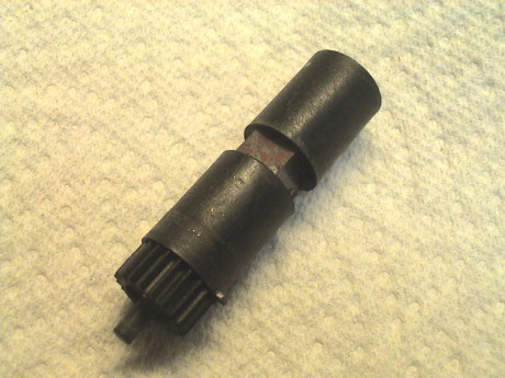 The rotor consists of three pieces. The
important thing to note is that with the red side of the magnet facing
upward, the small tab on the side of the gear must point to 3 o'clock
when looking from the gear end. If the magnet is reversed, the motor
will run backwards but it will still work.
The rotor consists of three pieces. The
important thing to note is that with the red side of the magnet facing
upward, the small tab on the side of the gear must point to 3 o'clock
when looking from the gear end. If the magnet is reversed, the motor
will run backwards but it will still work.
It is really important that the ways that the throwbar will ride in
are clean. This is the place that collects dirt and causes the most
drag.
 After the rotor and pole piece assembly
is reinstalled, rotate the tab so that it points straight up. It will
stay in this position. Note the plastic strips at 3 o'clock and 9
o'clock. The longer ends of these pieces should stick out from the ends
of the pole pieces. These limit the motor rotation to just under 180
°.
After the rotor and pole piece assembly
is reinstalled, rotate the tab so that it points straight up. It will
stay in this position. Note the plastic strips at 3 o'clock and 9
o'clock. The longer ends of these pieces should stick out from the ends
of the pole pieces. These limit the motor rotation to just under 180
°.
 With the
tab still point up, carefully place the throwbar in place so that it is
also centered. Then reinstall the cover without allowing the parts to
move. Check after reassembly that the throwbar moves symmetrically to
each side without excessive drag.
With the
tab still point up, carefully place the throwbar in place so that it is
also centered. Then reinstall the cover without allowing the parts to
move. Check after reassembly that the throwbar moves symmetrically to
each side without excessive drag.
 If you want to wire
your own turnout controls, use one of these diagrams, either
configuration will work. The top one uses a slightly more expensive
switch, the bottom one uses multiple diodes. I prefer the bottom one
which is also the guts of the LGB switch box. Many switches can use the
same pair of diodes. In both cases the switches need to be momentary
center-off. You'll find them designated:
If you want to wire
your own turnout controls, use one of these diagrams, either
configuration will work. The top one uses a slightly more expensive
switch, the bottom one uses multiple diodes. I prefer the bottom one
which is also the guts of the LGB switch box. Many switches can use the
same pair of diodes. In both cases the switches need to be momentary
center-off. You'll find them designated:
DPDT (on)-off-(on)
SPDT (on)-off-(on)
Note the ( ) in the designation. This means that that position is momentary. The switch is spring loaded and will return to the center position when the handle is released.
Solvent type cements, CA (super glue), epoxy and the stuff that comes with plastic building kits don't work at all. Regular contact cement works marginally well. GOOP brand silicone adhesives work a little better than contact cement, but still produce only a marginal bond.
 I've had a
little luck with Gorilla Glue, a polyurethane adhesive, for repairing
tie strips that have popped off the track. It looks like hell, but it
does bring the ties back to the track. The glue has to encapsulate the
rail foot and the area around the broken ties. It doesn't actually
stick to the ties, it forms to the broken plastic on the top of the tie
and mechanically holds the tie strip back on. This is most effective
for high value tie strips, like those in turnouts.
I've had a
little luck with Gorilla Glue, a polyurethane adhesive, for repairing
tie strips that have popped off the track. It looks like hell, but it
does bring the ties back to the track. The glue has to encapsulate the
rail foot and the area around the broken ties. It doesn't actually
stick to the ties, it forms to the broken plastic on the top of the tie
and mechanically holds the tie strip back on. This is most effective
for high value tie strips, like those in turnouts.
This turnout had the last 5 ties peeled off due to somebody stepping on it while it was not properly ballasted and supported. It was a $50 loss otherwise so I'll put up with the ugly glue joints.
Bob Poli writes: "I have also found that closing the space between the guard rail and active rail helps to keep the flange out of the frog. The only success I've had with bonding is to first drill small holes in the plastic rail then bond either brass or styrene strips, I prefer brass, to the side of the plastic rail. I use 5 minute epoxy. The real bond is created by the mechanical bond of the epoxy flowing through the holes and out the other side of the rail. It's best to coat the surface of the plastic rail first and make sure the epoxy goes through the holes. Then apply the brass strip which is preformed to the curve. Try and get some epoxy to encapsulate the brass as much as possible also rough up the brass with some emery paper to help the epoxy to stick. This should last indefinitely and it does help keep flanges between the rails."
The guard rail can also be refaced with a brass strip bent around the guard rail.
© 1997-2008 George Schreyer
Created Before Oct 5, 1997
Last Updated June 12, 2008