Bachmann Big Hauler Tips
[ Home ] [ Up ] [ Previous Page ] [
Next Page ]
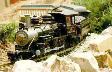 The Bachmann Big Hauler is a very
popular engine, primarily because it is visually attractive and they
can be usually found real cheap. However, the Big Hauler is intended to
be a low cost mass manufactured engine and therefore isn't built to be
highly durable. This doesn't mean that the Big Hauler is a total piece
of junk. It takes a little work, but it can be made to run long and
well.
The Bachmann Big Hauler is a very
popular engine, primarily because it is visually attractive and they
can be usually found real cheap. However, the Big Hauler is intended to
be a low cost mass manufactured engine and therefore isn't built to be
highly durable. This doesn't mean that the Big Hauler is a total piece
of junk. It takes a little work, but it can be made to run long and
well.
The Big Hauler has a 4-6-0 wheel configuration which is also called
a Ten Wheeler. This engine type replaced the 4-4-0 American type in the
latter half of the 19th century in fast freight and passenger service.
It was larger than the 4-4-0 and could pull a heavier load. The 4 wheel
leading truck allowed good tracking at fairly high engine speeds. The
2-6-0 Mogul and 2-8-0 Consolidation tended to replace the 4-4-0 in
freight service.
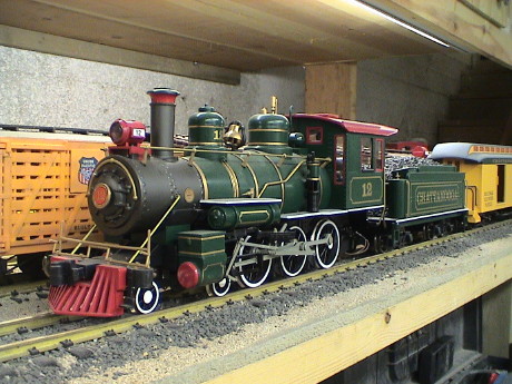
Bachmann's model is of a generic Baldwin product. The scale of the
model is debatable. Since Ten Wheelers were built by the thousands over
several decades and in various sizes, the model could represent a
smaller narrow gauge loco in 1:20.3 scale, or a larger loco in 1:24
scale. 10 Wheelers of the vintage modeled didn't get big enough so that
the model could reasonably represent a prototype in 1:29 or 1:32 scale.
There were larger and more modern 10 wheelers made, but they don't look
anything like this model.
The Bachmann Big Hauler has been built in many versions over the
years. I believe that the first version was the Radio Controlled Big
Hauler which was produced in about 1990. This version was manufactured
for many years thereafter in essentially the same form. It was never
very effective as an engine, but it got many of us started in Large
Scale. R/C sets could be found at toy discounters for as little as
$50.
Either around the same time or a little later, track powered
versions appeared. Entire sets could be found at the warehouse stores
for around $100 every Christmas time. The first versions had all
plastic detail, no external valve gear, very noisy internal gearing and
sheet metal wiper style power pickups. The engines evolved over the
years slowly gaining some external metal detail, "improved" power
pickups, external valve gear, several different internal gearing
arrangements, and a variety of different external details. The evolved
engines were called the "Plus" series, but in fact, there were many
versions of the "Plus" engines. Improvements were usually first applied
to engines sold individually, but eventually these improvements made it
into engines in found in sets as well.
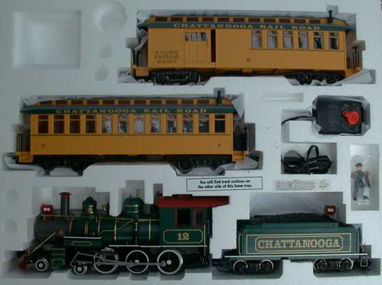
As of October 2000, a new set, the Chattanooga Railroad, appeared at
Costco stores for $90. The set has a Christmas style paint job on the
engine and a couple of yellow coaches. I grabbed one on impulse and I
found that Bachmann has made some serious improvements over the last
few years. This one runs as smoothly and quietly as any large scale
loco and is clearly worth the money. Don't expect that ALL of the Big
Hauler traits have been fixed however, you'll still have to tweak on it
a little.
Contents
Derailments
One of the major complaints against the Big Hauler is the fact that
it tends to derail easily. The main culprit is the pilot truck. You can
try these things to materially improve the tendency to derail.
Make sure that the truck moves and rotates freely. The most common
cause of problems is that the wires that connect the power pickups on
the leading truck get pinched and prevent free movement of the truck.
The symptom of this is the tendency for the front wheel on the inside
of turn to lift from the track. To handle 2' radius curves, the truck
must be able to move freely over the full width of the mounting slot.
If the wires are pinched, loosen the screws in bottom cover next to the
truck and free them.
The lead truck often needs to be lubricated to slide freely. Use
graphite lubricant on the sliding parts of the truck mount.
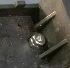
 Do not tighten the long screw near the pilot truck
too tightly. If you do, it will deflect the bottom cover some and may
bind up the movement of the lead truck. Also, the pilot truck may hang
up due to an interference between the truck pivot washer and nearby
screw. If a truck wheel tends to lift when entering a turn, especially
in reverse, look for this problem. You may have to grind down the screw
head a little to allow clearance.
Do not tighten the long screw near the pilot truck
too tightly. If you do, it will deflect the bottom cover some and may
bind up the movement of the lead truck. Also, the pilot truck may hang
up due to an interference between the truck pivot washer and nearby
screw. If a truck wheel tends to lift when entering a turn, especially
in reverse, look for this problem. You may have to grind down the screw
head a little to allow clearance.
Check the gauge of the pilot truck wheels. If the wheels won't slop
sideways 1/16" or so you'll have to regauge them. Remove the wheels on
the leading truck by pulling them off. Cut the plastic axle shorter by
about 1/32" and reinstall the wheels. On some locos, they are gauged
too narrowly already. The symptom of too narrow a gauge is that the
wheels tend to pop up at the frog of a turnout when they can't fit
around the guardrails on both rails at the frog. In this case, twist
and pull on them a little to create a small gap between the plastic
insulator and the wheel.
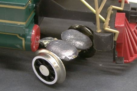 Weight the truck. My local Big 5 sporting
goods store carries 1 oz lead weights that are shaped like a flattened
oval. Use epoxy or Liquid Nails to glue 4 of these to the top of the
truck. Make sure that whatever weight that you use does not interfere
with the movement of the truck. Check especially for interference with
the frame or the cylinder heads.
Weight the truck. My local Big 5 sporting
goods store carries 1 oz lead weights that are shaped like a flattened
oval. Use epoxy or Liquid Nails to glue 4 of these to the top of the
truck. Make sure that whatever weight that you use does not interfere
with the movement of the truck. Check especially for interference with
the frame or the cylinder heads.
Look to your track. The Big Hauler is intolerant of rapid changes in
grade. If the track drops away from the pilot truck too rapidly, the
truck may actually bottom out and just hang there. When this happens,
it is not likely that the truck will come back down on the track. Note
that added pilot truck weights may interfere with the frame on turns if
your track has vertical gradients and the pilot truck spring gets
depressed. Either relieve the frame above the front pilot truck axle or
fix your track.
 If all of this fails, you can
completely change out the pilot truck mount. I had one 3rd generation
Big Hauler that just didn't get much run time because it derailed every
time at least a dozen spots around the layout. I finally ripped out the
stock truck mount and made my own from a piece of brass strip stock.
Now it tracks fine and doesn't derail anywhere on the layout.
If all of this fails, you can
completely change out the pilot truck mount. I had one 3rd generation
Big Hauler that just didn't get much run time because it derailed every
time at least a dozen spots around the layout. I finally ripped out the
stock truck mount and made my own from a piece of brass strip stock.
Now it tracks fine and doesn't derail anywhere on the layout.
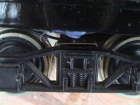
The new mount is attached to the lower cover right at the front at
the natural rotation point for the truck. The original coil spring is
discarded and the mounting post is cut down to 3/16" high. The new
mount provides the pressure that the truck needs to stay on the track
without adding friction that would prevent the truck from moving and
rotating to follow the track. The mount is intended to press down on
the center of the truck but not to impede its movement sideways or its
ability to yaw, pitch or roll. The spring has considerably more
vertical movement capability than the original mount so that the truck
is much more tolerant of abrupt changes in grade.
 The strip stock is drilled for #4 hardware and
bent at the fold lines. If you make this mod, you'll have to play with
the profile of the spring some, but it will work. At the truck end, the
spring is attached to the truck with the original screw reinstalled
loosely so that the truck can slop around a lot. The original coil
spring and washers are discarded.
The strip stock is drilled for #4 hardware and
bent at the fold lines. If you make this mod, you'll have to play with
the profile of the spring some, but it will work. At the truck end, the
spring is attached to the truck with the original screw reinstalled
loosely so that the truck can slop around a lot. The original coil
spring and washers are discarded.
 At the frame end, the spring is mounted with a
#4 screw and double nuts. Doubling nutting the screw allows the spring
to be drawn fairly tight against the frame but not so tight as to
prevent free rotation. The second nut is driven against the first to
lock them both in place.
At the frame end, the spring is mounted with a
#4 screw and double nuts. Doubling nutting the screw allows the spring
to be drawn fairly tight against the frame but not so tight as to
prevent free rotation. The second nut is driven against the first to
lock them both in place.
There is some raised lettering on the bottom of the frame that will
hang on the spring. It says "Bachmann China". This lettering needs to
be filed smooth.
If you've used the weights as described above, you'll need to remove
the rear ones. I removed all 4 and the truck still tracks properly.
I extended the power wires about an inch to allow them to loop
loosely so that the wires don't apply any forces to the truck at all.
The wires come back out the original mounting slot.
 Barry Olson of Barry's Big Trains sent me an
evaluation version of his replacement pilot truck for a Big Hauler. The
method I described above is actually a variation of this modification,
but Barry provides a whole new truck frame that is much "floppier" than
the stock Bachmann truck and can follow really bad track better. I had
one last unmodified Big Hauler so I ripped off the stock pilot truck
and installed this one. It was pretty easy but I did make some
changes.
Barry Olson of Barry's Big Trains sent me an
evaluation version of his replacement pilot truck for a Big Hauler. The
method I described above is actually a variation of this modification,
but Barry provides a whole new truck frame that is much "floppier" than
the stock Bachmann truck and can follow really bad track better. I had
one last unmodified Big Hauler so I ripped off the stock pilot truck
and installed this one. It was pretty easy but I did make some
changes.
-
Barry recommends drilling the mounting hole for the pivot arm 7/8"
back from the front of the bottom cover of the Big Hauler. I found that
I had to drill the hole 1-1/8" back to get the truck centered on the
cylinders.
-
He also recommended drilling a new hole to route the wires from the
truck back up into the loco. I elected to route them back up the curved
slot. To do that I needed to cut the tie wrap that he provided that
attaches the harness to the arm.
-
Barry provided two new spacers for the pilot wheels. These were so
tight that I didn't use them. I reused the old ones that had already
been cut down in length to regauge the wheelsets.
-
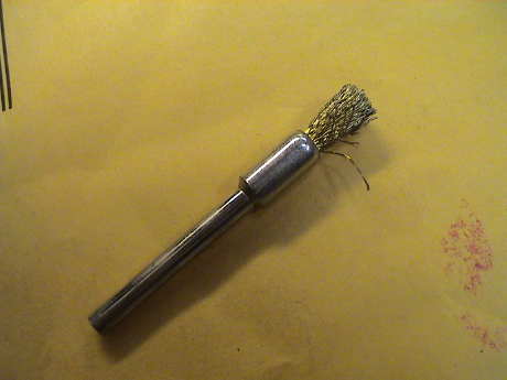 The frame
members of Barry's kit are metal but they are provided with a
non-conductive coating. This coating prevent current transfer from the
wheels to the frames. This coating would eventually wear off in the
right places, but I cleaned it out with a Dremel tool and this small
wire brush. After cleaning the accumulated gunk off the wheel shanks as
well, the power pickup from the truck was quite good.
The frame
members of Barry's kit are metal but they are provided with a
non-conductive coating. This coating prevent current transfer from the
wheels to the frames. This coating would eventually wear off in the
right places, but I cleaned it out with a Dremel tool and this small
wire brush. After cleaning the accumulated gunk off the wheel shanks as
well, the power pickup from the truck was quite good.
The result was a pilot truck that seemed to be able to ride over
pretty much anything. There were ivy leaves and stems on my track when
I did the initial test run. The pilot truck went right over this stuff
which eventually derailed the tender several times. The pilot truck
never did derail anywhere. However, the new truck is so light that it
is susceptible to undergauge track or overgauge wheelsets. If the
flanges don't fit between the rails properly, they will be squeezed up
and derail. If this happens with properly gauged wheels, then fix the
track.
[ Top ]
Power Pickup Problems
The Big Hauler is notorious for having flaky power pickup. The
engine is supposed to pick up power on 8 wheels, but in fact the
leading truck doesn't contribute much. This leaves four the drivers and
they get flaky too. Bachmann has made three different types of power
pickups, sheet metal wipers, spring loaded contacts and brass wheel
bushings. While the brass bushings are better than the others, they
develop problems too.
Old Style Wiper Contacts. If your engine is an old
one with strips of metal bent to make wipers, they may be completely
worn out or the glue that holds them to the side of the frame has
probably let go so that they have lost contact force. Either way, the
best bet is to scrap them and install LGB contacts. Then add metal
wheels and contacts to the tender. If the original ones aren't actually
worn out, they probably still don't touch the wheels at the extremes of
the axle play.
 On the older engines, I glue strips of styrene
to the outsides of the frame right above the axle slot to limit the
side play so that the contacts have a chance of making contact. I find
that it takes about 0.1" of shim on each side to control the axle
play.
On the older engines, I glue strips of styrene
to the outsides of the frame right above the axle slot to limit the
side play so that the contacts have a chance of making contact. I find
that it takes about 0.1" of shim on each side to control the axle
play.
 Piston Style
Contacts. If your engine has spring loaded contacts, you still
might want to shim the drivers as the contacts still don't reach all
the time. However, a better solution is to trash the Bachmann contacts
and install LGB contacts and then shim the axles. The Bachmann contacts
heat under heavy load and the spring looses tension. On this engine, a
spring actually melted the contact housing. To entirely replace a
contact, pull out the Bachmann contact and unsolder the wire from the
back. Then solder the wire to the end of an LGB contact and then
install it in the original hole with a glob of hot glue or your
favorite structural adhesive. These contacts will last a long time and
don't heat much when loaded.
Piston Style
Contacts. If your engine has spring loaded contacts, you still
might want to shim the drivers as the contacts still don't reach all
the time. However, a better solution is to trash the Bachmann contacts
and install LGB contacts and then shim the axles. The Bachmann contacts
heat under heavy load and the spring looses tension. On this engine, a
spring actually melted the contact housing. To entirely replace a
contact, pull out the Bachmann contact and unsolder the wire from the
back. Then solder the wire to the end of an LGB contact and then
install it in the original hole with a glob of hot glue or your
favorite structural adhesive. These contacts will last a long time and
don't heat much when loaded.
 Bushing Style Contacts. The third
style of power contact uses the wheel bushings to provide a connection
to the wheels. The bushings are connected to the engine with spring
contact fingers mounted to the lower cover. The front truck pickups are
wired to these contact springs as well. The wires to the engine body
plug into the contact strips so that disconnection or reversal of the
power contacts is easy.
Bushing Style Contacts. The third
style of power contact uses the wheel bushings to provide a connection
to the wheels. The bushings are connected to the engine with spring
contact fingers mounted to the lower cover. The front truck pickups are
wired to these contact springs as well. The wires to the engine body
plug into the contact strips so that disconnection or reversal of the
power contacts is easy.
All is not well with this new system however. I noticed a pronounced
sensitivity to track condition after several hours of running and a
couple of disassemblies. One of the spring contacts had become cocked
slightly and it rested on an insulator on the rear axle instead of the
bushing. Further, the bushings seem to be flakey. There is a wheel
position related hesitation on both axles when the engine is run from a
Kadee wheel brush. During the hesitation, the engine makes spitting and
growling sounds which may be related to motor thrashing while the
resistance of the bushing is changing. The engine runs completely
smoothly when the brush is used on the pilot wheels.
I isolated the problem to the bushings by connecting directly to the
bushing and the wheel. Other than using a conductive oil on the
bushings, there doesn't seem that there is much to be done. Perhaps
Bachmann will use a ball bearing on the next version as these seem to
work fine on locos from other manufacturers.
 Tender
modifications. There isn't any convenient place on the tender
trucks to mount power pickups. I epoxied a 1" square piece of styrene
to the bottom of the truck to make a platform where I could epoxy LGB
contacts. Solder wires to the contacts before you epoxy them down as
the heat of soldering will soften most epoxies. Connect the new
contacts back to the engine with some sort of small connector. You
might have to rummage around a local electronics or R/C car store to
find something suitable or use the method described in the Power Connector Tips page.
Tender
modifications. There isn't any convenient place on the tender
trucks to mount power pickups. I epoxied a 1" square piece of styrene
to the bottom of the truck to make a platform where I could epoxy LGB
contacts. Solder wires to the contacts before you epoxy them down as
the heat of soldering will soften most epoxies. Connect the new
contacts back to the engine with some sort of small connector. You
might have to rummage around a local electronics or R/C car store to
find something suitable or use the method described in the Power Connector Tips page.
 There is a cheaper way to
add power pickups to a Big Hauler tender that already has metal wheels.
Bachmann metal wheels have two drilled pits on the backside of the
wheel that make them unsuitable for piston style contacts. However, a
simple piece of bent brass strip stock will slip over the truck and
contact both wheels. It will even hold itself in place if the strip is
0.25" wide so that it captures itself between the truck frame and the
wheel flange. I used 0.016" thick stock, but thinner stock will do as
well. If you have it, thinner BeCu stock would work better as it has
more "spring" to it and it would be easier to get adequate pressure
with less drag. The downside of this cheap and dirty technique is that
it adds drag, something that Big Haulers can ill afford. However, even
conversion of one truck materially improves the power pickup
performance. This modification is completely reversible as there are no
modifications made to the structure of the tender at all.
There is a cheaper way to
add power pickups to a Big Hauler tender that already has metal wheels.
Bachmann metal wheels have two drilled pits on the backside of the
wheel that make them unsuitable for piston style contacts. However, a
simple piece of bent brass strip stock will slip over the truck and
contact both wheels. It will even hold itself in place if the strip is
0.25" wide so that it captures itself between the truck frame and the
wheel flange. I used 0.016" thick stock, but thinner stock will do as
well. If you have it, thinner BeCu stock would work better as it has
more "spring" to it and it would be easier to get adequate pressure
with less drag. The downside of this cheap and dirty technique is that
it adds drag, something that Big Haulers can ill afford. However, even
conversion of one truck materially improves the power pickup
performance. This modification is completely reversible as there are no
modifications made to the structure of the tender at all.
Leading Truck. There doesn't seem to be much that
can be done to improve the pickup from the stock front truck except by
using conductive oil on the bearings. Make sure that the wires are not
broken.
There is an aftermarket front truck available from Barry's Big
Trains, see the section above about derailments. This truck has better
power pickup than the stock truck once you clean the paint out of the
axle bushings.
[ Top ]
Gearing
There are at least SIX different motor/gearing
systems in use in Big Haulers. The later versions have the motor
mounted in a metal bracket with the gearing. I don't have a 4th
generation loco, but from reports from the field this one seems to be
more robust than the earlier versions. Even so, I've still heard of the
gearing getting mangled. Engines with this gearing will have a bulge on
the bottom cover right between the rear drivers. This bulge clears the
larger gear needed on the axle so that a reasonable reduction ratio
could be achieved without intermediate gearing. The 5th generation has
an intermediate reduction gear and a more substantial gearbox This
version seems to be holding up well in real life service. The 6th
generation is the "10th Anniversary Edition" (aka "Annie") version. I
don't have one of these, but reports from the field indicate that it
has the same gearing as the 5th generation drive, but with a 7 pole
motor. The 7 pole motor allows it to run more smoothly at very low
speed.
 The R/C Big Hauler uses a gearing
system that is similar to the early track powered version, but it has a
smaller lower voltage motor. I refer to this gearing as the 1st
generation as I believe that this was the first kind of Big Hauler
marketed.
The R/C Big Hauler uses a gearing
system that is similar to the early track powered version, but it has a
smaller lower voltage motor. I refer to this gearing as the 1st
generation as I believe that this was the first kind of Big Hauler
marketed.
 The early track
powered version (2nd generation) uses the same gearing as the first
generation but it has a larger motor. Due to all these gears, these
make the most noise. In my limited experience the gears don't seem to
strip as much as the 3rd generation type. The version has a large gear
reduction ratio so that the motor runs fast (hence lots of noise) but
this also reduces the load on the motor itself which tends to allow it
to draw a little less current than the later versions. This engine runs
fine on the puny power pack that is included in the Big Hauler sets.
The later versions, especially the 3rd and 4th generations, tend to
really tax the little power pack as the motors on the newer units run
at higher shaft torque, lower motor speed and therefore higher motor
current.
The early track
powered version (2nd generation) uses the same gearing as the first
generation but it has a larger motor. Due to all these gears, these
make the most noise. In my limited experience the gears don't seem to
strip as much as the 3rd generation type. The version has a large gear
reduction ratio so that the motor runs fast (hence lots of noise) but
this also reduces the load on the motor itself which tends to allow it
to draw a little less current than the later versions. This engine runs
fine on the puny power pack that is included in the Big Hauler sets.
The later versions, especially the 3rd and 4th generations, tend to
really tax the little power pack as the motors on the newer units run
at higher shaft torque, lower motor speed and therefore higher motor
current.
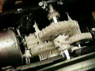
 The 3rd generation version
uses a brass worm on the motor and plastic reduction gears. These seem
to the most prone to wiping out the gearing. Worm gears, when placed
under load, tend to thrust perpendicular to the motor shaft. If the
motor is not mounted firmly (see below), this thrust tries to make the
worm walk over the teeth on the meshed gear. This is evidenced by a
clear popping or clicking noise, particularly when running loaded in
reverse. This version was produced from the early 90's to about 1997 so
the majority of Big Haulers out there, including many of the "Plus"
versions will have this type of gearing.
The 3rd generation version
uses a brass worm on the motor and plastic reduction gears. These seem
to the most prone to wiping out the gearing. Worm gears, when placed
under load, tend to thrust perpendicular to the motor shaft. If the
motor is not mounted firmly (see below), this thrust tries to make the
worm walk over the teeth on the meshed gear. This is evidenced by a
clear popping or clicking noise, particularly when running loaded in
reverse. This version was produced from the early 90's to about 1997 so
the majority of Big Haulers out there, including many of the "Plus"
versions will have this type of gearing.
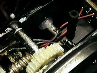
 I don't have a 4th generation Big Hauler, but
Dan Pierce sent a photo of his. This one uses a worm on the motor and a
single gear on the axle. The motor and rear axle are held in a bracket
made from a piece of sheet metal bent into a U shape. The axle gear is
fairly wide and centered on the axle. There is a bump on the lower
cover to clear this gear. The bump is also centered.
I don't have a 4th generation Big Hauler, but
Dan Pierce sent a photo of his. This one uses a worm on the motor and a
single gear on the axle. The motor and rear axle are held in a bracket
made from a piece of sheet metal bent into a U shape. The axle gear is
fairly wide and centered on the axle. There is a bump on the lower
cover to clear this gear. The bump is also centered.
This version should have had a lower gear failure rate, but it
didn't appear to work to well. There have been many reports of this
configuration eating its gearing under load.
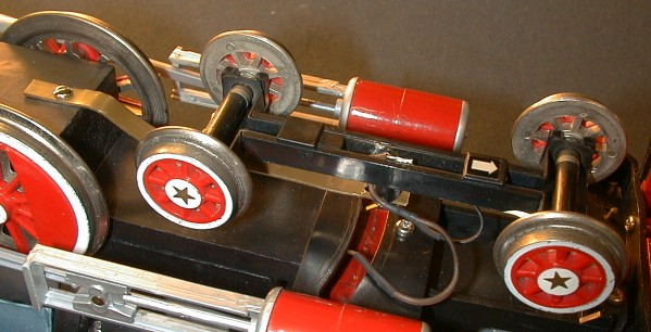
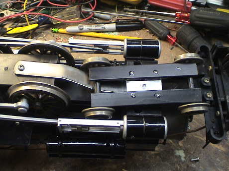
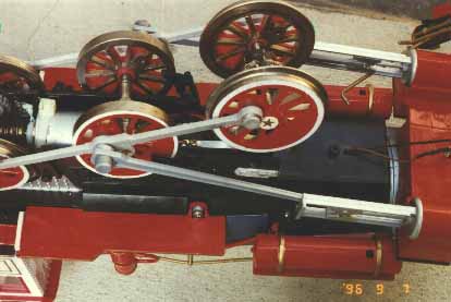
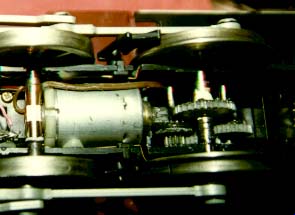
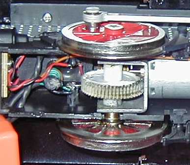
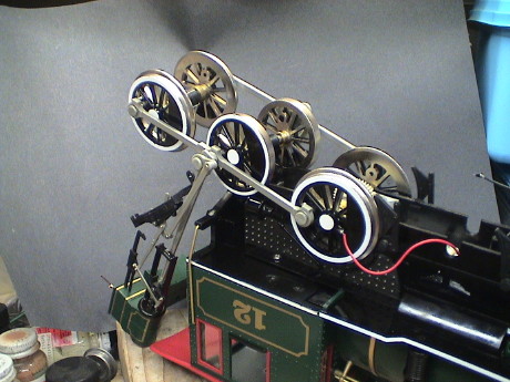
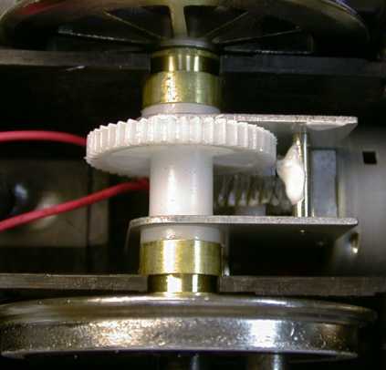 The 5th version is shown
in the photo. This version appeared sometime during 2000. This one has
an intermediate reduction gear and a more substantial metal gearbox
assembly. The axle gear is narrower and offset from the center. The
bump in the lower cover is also offset from the center.
The 5th version is shown
in the photo. This version appeared sometime during 2000. This one has
an intermediate reduction gear and a more substantial metal gearbox
assembly. The axle gear is narrower and offset from the center. The
bump in the lower cover is also offset from the center.
There have been reports that this version has a tendency to slip.
The large axle gear is apparently not attached well enough to the axle
and can slip on the axle. Mine has not done this, but those with the
problem have reported that if a hole is drilled in the plastic bushing
next to the large gear and right through the axle and the bushing on
the other side and a pin is inserted, the axle then becomes locked to
the gear. The hole should be just large enough to clear the pin. A
piece of steel wire would work. Then ends should be folded down to
capture the wire.
[ Top ]
Motor Mount Modifications
A common problem with Big Haulers is stripped gears. There are a
variety of causes, but a major one is that the motor mount is
inadequate. Other causes are heavy loads in high heat and inadequate
lubrication. I can't recommend much about operation in high heat except
maybe don't do it, but the other problems can be fixed.
In the earlier versions, the motor is held in by two mechanisms,
neither of which is adequate. Glue holds it in place, that is until the
motor heats up and the glue lets go. Also the motor is pinched in
saddles. Unfortunately, one of the saddles is in the bottom cover which
is not very stiff. Under heavy loads, the whole bottom cover will flex
in response to motor loads and the motor squirms around.
For those of you that have the
gearing with the brass worm and multiple reduction gears (3rd
generation), you should make this modification to the motor mounts or
you probably WILL strip some gears eventually. The
earlier versions without the brass worm don't seem to need this
modification, but it won't hurt. The 4th and 5th generations don't seem
to need this modification either.
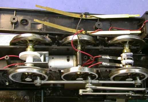
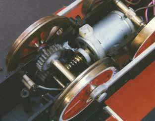
Open both the top and bottom of the engine and wrap a long heavy
duty cable tie around the motor and the iron weight mounted on top of
the frame as shown in the photo above. Cinch that sucker down
TIGHT. This holds the motor in the frame half of the
saddles and materially improves problems with stripped gears. This fix
applies only to 3rd generation Big Haulers, which went out of
production in the late 1990's.
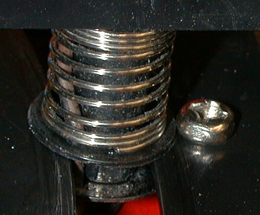
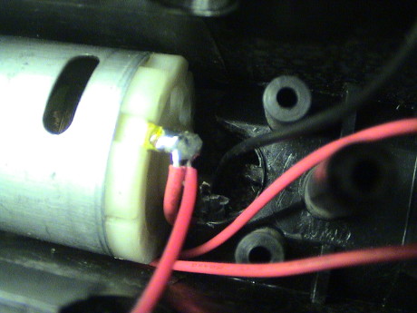
Now that I've recommend that you cable tie the motor, you
MUST make sure that you have the new motor mount ring.
The new motor mount ring is a white plastic ring that wraps around the
motor bearing on the worm end. This part can be clearly seen in the
photo. The old type is yellowish clear plastic and is much softer. If
you cable tie the motor down with an old ring, the ring will slowly
deform and the worm will bear hard against the first gear. This
increases the load on the motor and wears the gears and bearings out
much faster. If you have an old style ring, write Bachmann and ask for
a new one, they'll send it out free.
If the motor mounts are damaged, perhaps by exposure to heat, then
the motor MAY sit too deeply in the mount already. If you apply the
cable tie, you can then cause the worm to bind into the driven gear and
either load or stall the motor. Before you cinch the tie, rotate the
worm by hand to feel the "normal" amount of drag. If the drag increases
after you cinch the tie, cut it out because it will cause more problems
that it solves. If the drive has further problems, you may want to
secure the motor with a high temperature adhesive, scrap the unit or
get a BBT upgrade chassis.
If you already have stripped gears but the rest of the engine is
intact, send Bachmann the bad gears and they'll probably send new ones
back for free.
I've probably had better luck than many people with Big Hauler gears
because my engines lead a sheltered life. They always stay in a cool
basement which never gets warmer than 60 F. This is a far cry from
sitting on the ground in Phoenix in the summer where the ground level
temperatures can exceed 140 F. At these temperatures, the plastic gears
will soften and be much more susceptible to being mangled.
Even so, I spun the gear on the driver axle on an old Big Hauler.
This happened after I added weight and could pull a heavier load. It
was a simple matter to repair the gear, almost in place. I slid the
gear off the knurled section of the axle and then coated the knurling
with a filled epoxy. I then slid the gear back over the knurling to the
proper position and allowed the epoxy to set. The epoxy grabbed on the
knurling and on the ripped up plastic that had slid on the knurling and
mechanically bonded the gear back on the axle. This patch has not given
me any more trouble in 13 years of blatant abuse.
I think that one of the basic reasons for Big Haulers stripping
gears more often that other locos is that there is only one gear train
to take up the load. Other locos usually have 2 or 4 gear trains so
that the stresses placed on those gears are proportionally less. Add
this to some heat and sloppy meshing and disaster is very likely.
The Delton C-16 had only one drive gear and it has a reputation for
stripping and wearing gears too. BBT's Bachmann conversion also has
only one gear train, but it is an industrial strength system and
doesn't seem to suffer the same difficulties.
[ Top ]
The Radio Controlled Big Hauler
The Big Hauler was made in a R/C version. This engine looked
externally identical to an early track powered version but ran from
internal batteries and a rudimentary radio control system. The engine
was available only in train sets.
The R/C gear is a simple AM system that operates at 27 MHz although
there may have been some 49 MHz systems out there as well. If the
engine ran out of range of the transmitter, it would run at its default
setting of full forward until it came back into range. This made
backing moves difficult as the engine would try to go forward every
time it lost its RF signal which would often result in severe
bucking.
When working properly, the motor control system is very effective.
The engine can be nudged along at very low speeds and it runs steadily,
that is as long as you are close enough to the engine to prevent it
from running away.
The R/C receiver is mounted on a circuit board in the smoke box and
is a little difficult to get to. The antenna wire runs down the left
side of the engine and loops through the cab. It has to be disconnected
at a screw terminal about halfway along the left side of the boiler
before the shell can be removed.
The RF receiver circuits take up roughly the front 1/3 of the
circuit board. The H-bridge motor controller takes up the center 1/3 of
the board and the sound system takes up the rearmost 1/3 of the board.
The wire leading to the tender carries the signal to the speaker. In a
track powered Big Hauler, this wire carries the pulses from the sound
switch.
The R/C Big Hauler is designed to run from 9 volts generated by six
internal D batteries. These batteries also give the engine quite a bit
of weight and with the traction tires, the engine can pull fairly well
on good batteries. However, the engine can also flatten the batteries
fairly quickly. There is an adapter cable included to use an R/C car
type sub-C rechargeable battery pack. The voltage of the sub-C pack is
typically 7.2 volts so that the engine runs a little slower on the
rechargeable battery than a good set of alkaline batteries.
The R/C Big Hauler has another problem. Its plastic drivers are
intended to run on plastic track. After extended running on tight
radius metal track, the flanges will get roughed up and eventually,
they will generate so much traction against the rails in turns that the
outside rear driver will literally climb the rail and derail. As much
as I tried, I couldn't get the wheel resurfaced adequately so I
replaced the drivers with a metal set that was made for the same
vintage track powered Big Hauler. The gearing was identical so it fit
right on. However, the downside is that for some reason, every time the
engine ran in reverse over a turnout, some sort of radio interference
was generated and the engine tended to try to reverse and buck. I never
did fix this problem, we just had to stay near the engine so that the
radio signal was fairly strong. We did find that by touching the
transmitter antenna to the track, that the track tended to conduct the
radio signal to the engine and it did run better.
The R/C Big Hauler was not equipped with smoke, but I found that the
smoke stacks themselves make an excellent replacement oil stack for a
Bachmann Shay. The stack needs to be filed before it will fit, but once
in place and airbrushed with a light coating of engine black, it
matches the Shay smokebox color very well. The sound generators also transplant into a Shay well and produce
a credible chuffing sound for considerably less investment than a
digital sound system.
[ Top ]
Periodic Maintenance
Proper lubrication is critical in maintaining a Big Hauler's health.
Every few months, you should follow a lubrication schedule.
- Remove the bottom cover as described below.
- Lubricate whatever gearing is in your model Big Hauler with heavy
gear grease or heavy gear oil.
- Lubricate the motor bearings with medium or light oil. Besides
being generally good practice, this helps prevent hot bearings which
will melt the motor mounts.
- If you can get at it, lubricate the commutator (inside the motor)
with a very small amount of conductive oil. There may or may not be an
access port to inspect the commutator on your motor.
- Lubricate the axle bearings with heavy gear grease or heavy gear
oil.
- Replace the bottom cover.
- Lubricate the siderod bearings and crosshead with medium to light
oil.
- Lubricate the pickups with a very small amount of conductive oil.
Catch the bushings on the pilot truck too.
- Lubricate the pilot truck mount (the curved slot) with
graphite.
[ Top ]
What To Do In Case Of Total Devastation
If your Big Hauler is really too far gone for remedial work, you
have several options:
- Toss it in your scrap box for parts.
- Convert it to a stationary boiler for your engine house.
- Send it back to Bachmann with $20. Under the limited lifetime
warranty, they'll do what it takes to fix it. You may get a whole new
bottom end but you'll still have a Bachmann Big Hauler.
- Send your wheels and $199.99 to Barry's Big Trains. Barry will
supply a totally new and bullet proof bottom end for the engine. People
that have done this rave about his work. I've been waiting for one of
mine to totally bite the dust before I send it to him, but the damn
things refuse to crap out. For a little extra, he'll convert it to a
2-8-0. Barry can also be reached at PO Box 1119, Tolleson, AZ
85353-1119 or at (623) 936 6088 or by Email.
[ Top ]
After market Upgrades
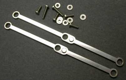 Barry of Barry's Big Trains sent me a set of
his new laser cut stainless steel siderods for the Big Hauler. He makes
these because the Bachmann siderods sometimes don't fit his mechanisms
due to some rather poor tolerance control at the Bachmann factory.
After looking around for an engine to install them on, I realized that
none of my engines really needed them. I did test fit them on an R/C
Big Hauler and found that they fit fine. I put the old rods back on
because it didn't seem right to put such a nice set of hardware on an
engine that hardly runs anymore. I'm going to save them for an eventual
BBT chassis upgrade.
Barry of Barry's Big Trains sent me a set of
his new laser cut stainless steel siderods for the Big Hauler. He makes
these because the Bachmann siderods sometimes don't fit his mechanisms
due to some rather poor tolerance control at the Bachmann factory.
After looking around for an engine to install them on, I realized that
none of my engines really needed them. I did test fit them on an R/C
Big Hauler and found that they fit fine. I put the old rods back on
because it didn't seem right to put such a nice set of hardware on an
engine that hardly runs anymore. I'm going to save them for an eventual
BBT chassis upgrade.
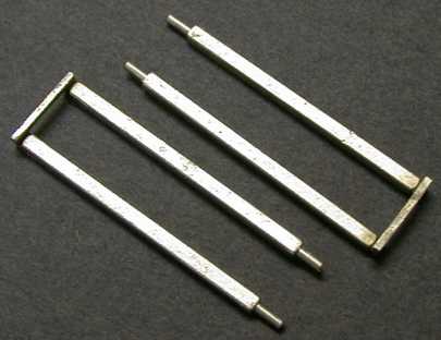 Barry also sent me a set of metal crosshead guides. These are intended
to replace the ones that so often break off Big Haulers. I didn't
install these either but I did overlay them on a couple of Bachmann
engines and it looks like they would fit well. Some Big Haulers have
bumps on the stock plastic guides that cause the engine to click as it
runs. These parts would fix that.
Barry also sent me a set of metal crosshead guides. These are intended
to replace the ones that so often break off Big Haulers. I didn't
install these either but I did overlay them on a couple of Bachmann
engines and it looks like they would fit well. Some Big Haulers have
bumps on the stock plastic guides that cause the engine to click as it
runs. These parts would fix that.
Barry also makes a replacement front truck, see the section above
about tracking and derailments.
[ Top ]
Sound System Modifications
The Bachmann sound system can be inexpensively upgraded to sound
much better. An article (Feb. 98) in Garden Railways Magazine describes
the three upgrades to the stock Bachmann sound system. You can also
find a draft of the article at Better Big Hauler Sound for Under a
Buck.
- Chuff profile modifications
- Four chuff/wheel turn modifications with unequal volume chuffs
- Automatic sound shutoff when the engine stops.
The wire between the engine and tender usually becomes very stiff
with age or in the cold and the connector can tend to pull out in turns
or it may even tip the engine or tender. This can cause the sound to
become intermittent or stop altogether or it can cause derailments. I
replace it with fine gauge speaker wire. You can get the old contacts
out of the connector shell by using a fine point tool to depress the
clips that hold the contacts into the shell. It is easier to do it if
you cut the old wire and strip off the sleeving so that you can tug on
the old wires individually. If you don't pull the contacts out of the
shell, then leave a half inch or so of wire in the old shell and splice
on a new flexible wire.
For those of you that haven't bothered to trace it out, here is my
interpretation of the schematic of the sound generator in a Big Hauler.
This same circuit is included on the rear third of the circuit board in
an R/C Big Hauler.
Stock Bachmann Sound Board
As of sometime in 2000, Bachmann has changed the sound board. The
new circuit can be identified from the outside of the tender as it has
a volume control knob underneath the tender floor. It no longer will
blow a continuous chuff when stopped, but the chuff profile is poor,
it's decay is way too long. This can be fixed, see Better Big Hauler Sound for Under a
Buck for more info.
The new board seems to have some leakage that will flatten the
battery over a period of a few months. If you are not going to use it
for awhile, it might be best to turn it off with the volume control
under the tender.
[ Top ]
Smoke System
If the smoker works, but smokes weakly, it may be possible to
improve the smoke output at zero cost, see my Smoke Tips page for details. The
downside is that it may go through smoke fluid faster and be even more
likely to burn up if it runs dry.
The Bachmann smoke system tends to burn up fairly often, so if you
like smoke, you are better off replacing the smoke generator with an
LGB unit, see Smoke Tips for a
little more information on the smoke units. The Ten Wheeler smoke
generator is similar to the one in the Shay, and the same modifications can be
done.
There are a couple of differences between the Big Hauler and the
Shay. The Ten Wheeler smoke unit is fastened from the bottom so you
have remove the shell to remove the smoke generator. Also, the stack on
some units is just a little too small to accept an LGB smoke unit so
you will have to drill it out. A 3/8" drill is just right, the smoke
unit body will drop through and the lip on the top will hold the unit
right at the top of the stack. The Shay had a conveniently placed hole
in the heat sink to allow the mounting of the regulator IC, on the Big
Hauler, I had to drill a mounting hole. Other than that, the
modification is essentially the same as for the Shay.
If your stack has a "final" on the top it may not fit properly with
an LGB smoke unit installed. it can either be discarded or ground down
to clear the lip of the LGB smoke unit.
If your Big Hauler has a funnel stack, you'll have to figure out the
mounting yourself. I don't have a funnel so I haven't worked out the
details.
 This is the circuit that I used
for the Big Hauler smoke upgrade. I wired it to improve the brightness
of the headlight too. My headlight had burned out so I replaced it with
a grain-of-wheat bulb (Radio Shack 272-1092c). This is a 12 volt bulb
so it needed a 47 ohm resistor in series with it to drop the voltage at
the bulb to about 12 volts so that it wouldn't burn up immediately. You
may also need a resistor in series with the Bachmann bulb if it burns
too bright. You could also use a 5 volt Grain-of-Wheat bulb and wire it
at the output of the regulator. You will then have to wire the smoke
switch directly in series with the smoke unit so that you can shut off
the smoke without turning off the headlight.
This is the circuit that I used
for the Big Hauler smoke upgrade. I wired it to improve the brightness
of the headlight too. My headlight had burned out so I replaced it with
a grain-of-wheat bulb (Radio Shack 272-1092c). This is a 12 volt bulb
so it needed a 47 ohm resistor in series with it to drop the voltage at
the bulb to about 12 volts so that it wouldn't burn up immediately. You
may also need a resistor in series with the Bachmann bulb if it burns
too bright. You could also use a 5 volt Grain-of-Wheat bulb and wire it
at the output of the regulator. You will then have to wire the smoke
switch directly in series with the smoke unit so that you can shut off
the smoke without turning off the headlight.
If your Big Hauler smoke unit is still working, you can just add the
part of the circuit to the left of the switch and your smoke will run
better at low speed with PWC. However it will also be at more risk if
you should let it run dry.
[ Top ]
Headlight Replacement With A White LED
Bright white LEDs (Light
Emitting Diode) are available that are much brighter than most
incandescent bulbs used as large scale locomotive headlights. This
section describes changing the headlight in the circuit above to an
LED.
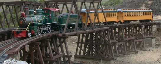
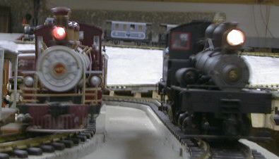 The Big Hauler on the left has a Radio
Shack 12v 60 mA Grain-of-Wheat bulb running at its ratings. The Shay on
the right has the stock Bachmann bulb that came on the early production
Shays, later Shays have a much more wimpy standard yellow LED as a
headlight. You can see that the Big Hauler light is not very bright as
compared to the Shay.
The Big Hauler on the left has a Radio
Shack 12v 60 mA Grain-of-Wheat bulb running at its ratings. The Shay on
the right has the stock Bachmann bulb that came on the early production
Shays, later Shays have a much more wimpy standard yellow LED as a
headlight. You can see that the Big Hauler light is not very bright as
compared to the Shay.
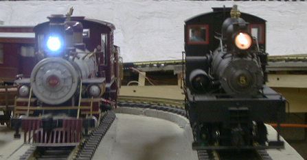 This photo shows the same two
engines after a bright white LED has been installed in the Big Hauler.
The LED is running at its rated 20 mA vs the 60 mA that the old GOW
bulb took. Now compare the brightness of the two locos using the Shay
as a reference to see how much brighter the white LED is.
This photo shows the same two
engines after a bright white LED has been installed in the Big Hauler.
The LED is running at its rated 20 mA vs the 60 mA that the old GOW
bulb took. Now compare the brightness of the two locos using the Shay
as a reference to see how much brighter the white LED is.
 This is the modification
that was made to the smoke circuit above. The LED runs off rectified
track power and its current is controlled with a large series resistor
that approximates a true current source. The right value for the
voltage available is 600 ohm. I got the value by paralleling two 1200
ohm resistors. With Aristo PWC on th track, the LED comes on very
bright before the engine even starts to move.
This is the modification
that was made to the smoke circuit above. The LED runs off rectified
track power and its current is controlled with a large series resistor
that approximates a true current source. The right value for the
voltage available is 600 ohm. I got the value by paralleling two 1200
ohm resistors. With Aristo PWC on th track, the LED comes on very
bright before the engine even starts to move.
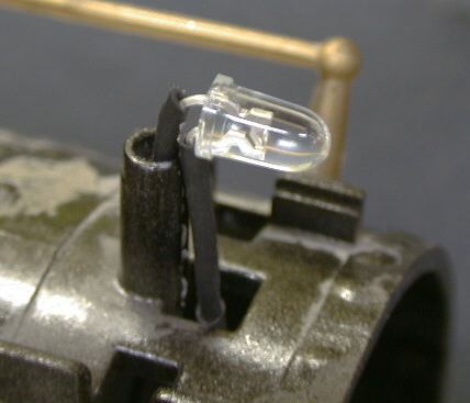 The LED is installed
in place of the original lamp, but it has to face forward to project
its beam. The LED leads are insulated with shrink tube and one lead is
pressed into the original support. The support had to be drilled out
just a little to accommodate one lead and its shrink tube. The other
lead goes into the boiler just in front of the support. A dab of hot
glue holds the LED in position.
The LED is installed
in place of the original lamp, but it has to face forward to project
its beam. The LED leads are insulated with shrink tube and one lead is
pressed into the original support. The support had to be drilled out
just a little to accommodate one lead and its shrink tube. The other
lead goes into the boiler just in front of the support. A dab of hot
glue holds the LED in position.
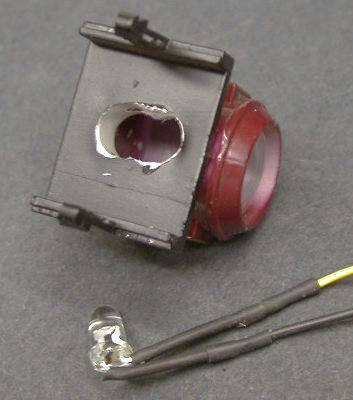 The headlight housing can just be
pulled off the loco. The LED wouldn't go into the housing until a
little gouging was done. The original hole is drilled out to 1/4" and
another 1/4" hole is drilled in front of it so that the two holes merge
together. The resultant shape is then filed out to an oval. This allows
the LED housing to slip up inside the headlight housing.
The headlight housing can just be
pulled off the loco. The LED wouldn't go into the housing until a
little gouging was done. The original hole is drilled out to 1/4" and
another 1/4" hole is drilled in front of it so that the two holes merge
together. The resultant shape is then filed out to an oval. This allows
the LED housing to slip up inside the headlight housing.
The hard blue color of the LED can be toned down a bit by painting
the LED housing with a very thin coat of Tamiya Clear Yellow paint.
Keep the layer VERY thin, dry brushing or airbrushing works well. The
yellow paint cuts the blue color. If you use too much the light will be
distinctly yellow or even green.
[ Top ]
Taking A Big Hauler Apart
The Big Hauler is designed to be cheap to manufacture so its fairly
easy to put together and therefore, it is easy to take apart.
- The Bottom Side
- Prop the engine on two scraps of wood under the cab
roof so that it also rests on its smokestack. This prevents the whistle
and dynamo exhaust from being damaged.
- The bottom cover comes off with four screws down the
center line of the bottom cover. Remove all four screws
- Pry out the pilot support rods from the sides of the
smoke box.
- Carefully lift off the bottom cover and place it
sideways in front of the cylinder saddle.
- Put the long screw back in the middle of the cylinder
saddle so that it helps hold the saddle in place.
- Do your work inside
- Reassemble in the reverse order. Be very careful not
to pinch the wires to the lead truck when you reinstall the cover. Also
watch for the hook at the rear as it tends to flop to the side and when
in that position it makes getting the cover back on difficult.
- The Top Side
- Pry the pilot support rods from the sides of the
smoke box
- Remove two screws under the cab
- Remove two screws from the sides of the boiler near
the lower center of the boiler
- Remove the long screw under the cylinder saddle
- Remove four screws from under the air tanks. The
tanks will fall off.
- Carefully lift the shell off. Be careful about the
wires to the smoke unit and headlight.
- Do your stuff
- While you're in there, glue 1 or 2 lbs of lead on top
of the cast iron weight. Note that extra weight will add capability to
pull more cars, which means that you can make the motor work harder,
which means that the motor will run hotter. If you haven't reinforced
the motor mounts, adding weight WILL result in rapid
failure of the engine.
- Reassemble in opposite order.
[ Top ]
The Chattanooga Choo Choo
 Bachmann
has come out with a new low cost set ($89.99 in Oct 2000 at Costco
while they've got them) with a significantly upgraded locomotive. The
set has the same coaches are previous sets, the same light duty track
and the same wimpy power pack (but with no AC output terminals). There
is an engineer figure in the cab. A fireman figure, a comic book style
instruction book and a VHS video are also included. All the wheels in
the set are metal.
Bachmann
has come out with a new low cost set ($89.99 in Oct 2000 at Costco
while they've got them) with a significantly upgraded locomotive. The
set has the same coaches are previous sets, the same light duty track
and the same wimpy power pack (but with no AC output terminals). There
is an engineer figure in the cab. A fireman figure, a comic book style
instruction book and a VHS video are also included. All the wheels in
the set are metal.
The new loco pulls only marginally well, but due to the new axle
bushings and improved gearing, it might be able handle increased weight
for better traction. The results of some testing can be found on my Tractive Effort Tests
page. The engine draws less current that most locos making it a good
candidate for battery power.
The locomotive detail is improved as well. All the grab irons are
brass rod and there is a Walsharts type of valve gear installed. The
headlight is unchanged, as is the smoke unit. The tender still has all
plastic details.
The sound system in the tender has been "upgraded" too. It now
issues a timed chuff when it is triggered so that it will no longer
stop with a chuff constantly blowing. However, the decay time of the
chuff is way too long so that the chuffs tend to blend together at high
speeds. This is easily fixed, see Better Bachmann Sound for About a
Buck for instructions.
 The set
comes packed with the loco, a combo coach and an observation coach
(without drumhead). Both the coaches are lighted using the standard 9
volt battery. These coaches eat up expensive 9v batteries fairly
quickly. Since the wheels are metal and the pickup pockets are still
there, the lighting can be converted to track power fairly
easily.
The set
comes packed with the loco, a combo coach and an observation coach
(without drumhead). Both the coaches are lighted using the standard 9
volt battery. These coaches eat up expensive 9v batteries fairly
quickly. Since the wheels are metal and the pickup pockets are still
there, the lighting can be converted to track power fairly
easily.
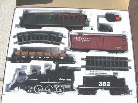 A similar set is available at Sam's Club for $99.99. I
haven't seen this set (the photo was provided by Lou Grandieri) but the
Bach-man says that the set has the same new mechanism as the
Chattanooga Railroad set. The engine doesn't have the external valve
gear but the paint job is much better, less work will be required to
convert the road name and weather the loco. I also understand that
Orchard Supply Hardware has yet a third special set for a similar
cost.
A similar set is available at Sam's Club for $99.99. I
haven't seen this set (the photo was provided by Lou Grandieri) but the
Bach-man says that the set has the same new mechanism as the
Chattanooga Railroad set. The engine doesn't have the external valve
gear but the paint job is much better, less work will be required to
convert the road name and weather the loco. I also understand that
Orchard Supply Hardware has yet a third special set for a similar
cost.
The mechanism in this loco is all new, at least to
me. The troublesome wheel contact wipers and plungers are gone,
replaced with metal bushings on the axles that both pick up power and
support the locomotive. These bushings are substantially heavier duty
than the plastic bearings in former Big Haulers. The bottom engine
cover is electrically connected to the loco with two small plugs so
that the entire cover can be removed and placed aside during loco
maintenance. This also means that the power pickups can be disconnected
easily for a battery power conversion without making any permanent
modifications to the engine.
The locomotive gearing is
also substantially upgraded. It is now a two step reduction gear system
enclosed in a metal frame. The motor is also attached to this frame so
that the problems that the older locos had with gear alignment may be
solved. The gear train runs nearly silently.
When I had the loco open for lubrication, I checked the minimum
speed. Unloaded, the drives will turn at 6 RPM at only 0.9 volts DC.
This is the lowest starting voltage that I have measured so far on any
loco. The mechanism would actually run as low as 0.7 volts, but it
would not run consistently.
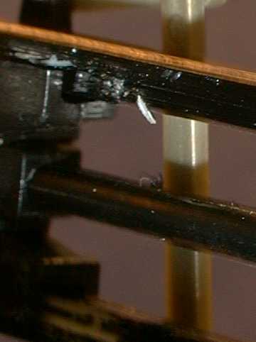 This loco had
an audible tick in the valve gear, once per driver turn. I tracked it
down to a mold mark on the inside of the lower crossguide on one side.
The mark is about halfway down the length of the crossguide, also about
halfway between the crosshead and the little sliver of plastic in the
photo. The crosshead would pop over the mark and make a click. A little
careful file work removed the mold mark and the tick.
This loco had
an audible tick in the valve gear, once per driver turn. I tracked it
down to a mold mark on the inside of the lower crossguide on one side.
The mark is about halfway down the length of the crossguide, also about
halfway between the crosshead and the little sliver of plastic in the
photo. The crosshead would pop over the mark and make a click. A little
careful file work removed the mold mark and the tick.
Converting a Big Hauler to DCC
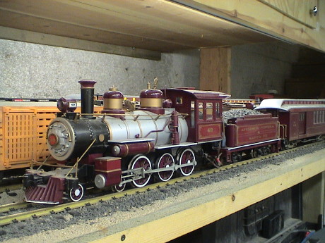 I have converted the GIRR Mtn Div to operate on DCC
as well as DC track power. As more locos are converted, the DC system
is used less and less. My oldest loco is this ATSF Big Hauler, a 2nd
generation unit. As of this writing, this loco has been running on the
Mtn Div for 18 years. I didn't expect it to last this long but it has
held up well so I invested $16 in a HO sized decoder for this loco. The
2nd generation units use a smaller high speed motor than the later
units. The high motor speed and multiple stage gearing creates a fair
amount of gear whine, but it is not overwhelming so I still run the
loco. Because of the smaller motor, this loco draws the least current
anything I have except the Bachmann railtruck which won't pull
anything. The Big Hauler handles it's assigned 3 coach set quite nicely
on the 4.2% grades of the GIRR. It struggles on the 5.2% grade of the
spiral but it does it. Because of the low current draw, I could use an
inexpensive HO decoder, a Digitrax DH123D which is rated at 1.5 amps,
this loco only draws half that.
I have converted the GIRR Mtn Div to operate on DCC
as well as DC track power. As more locos are converted, the DC system
is used less and less. My oldest loco is this ATSF Big Hauler, a 2nd
generation unit. As of this writing, this loco has been running on the
Mtn Div for 18 years. I didn't expect it to last this long but it has
held up well so I invested $16 in a HO sized decoder for this loco. The
2nd generation units use a smaller high speed motor than the later
units. The high motor speed and multiple stage gearing creates a fair
amount of gear whine, but it is not overwhelming so I still run the
loco. Because of the smaller motor, this loco draws the least current
anything I have except the Bachmann railtruck which won't pull
anything. The Big Hauler handles it's assigned 3 coach set quite nicely
on the 4.2% grades of the GIRR. It struggles on the 5.2% grade of the
spiral but it does it. Because of the low current draw, I could use an
inexpensive HO decoder, a Digitrax DH123D which is rated at 1.5 amps,
this loco only draws half that.
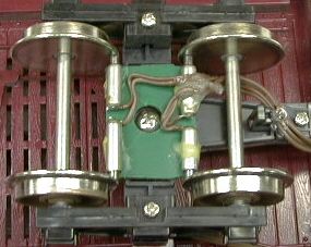
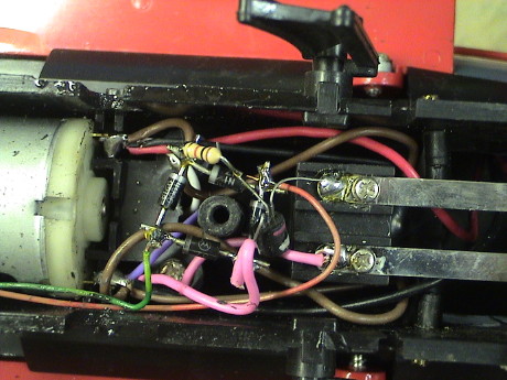
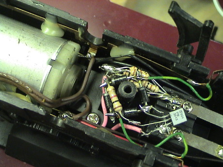 This
is what it looked like underneath before I started. The transistor and
diodes are an add on kludge to stop the chuff when the track voltage
goes to zero, see Better
Bachmann Sound for About a Buck for the details of this hack. The
drivers have been pulled to reveal the motor connections. The tabs from
the motor are soldered directly to the brass strip that is used for the
power pickups in this version. The wires leading forward from those
points are for the pilot truck and the headlight/smoke unit. The brown
wires lead to the back go to additional connectors that I added to
allow the tender to pick up power as well and feed it forward the the
engine.
This
is what it looked like underneath before I started. The transistor and
diodes are an add on kludge to stop the chuff when the track voltage
goes to zero, see Better
Bachmann Sound for About a Buck for the details of this hack. The
drivers have been pulled to reveal the motor connections. The tabs from
the motor are soldered directly to the brass strip that is used for the
power pickups in this version. The wires leading forward from those
points are for the pilot truck and the headlight/smoke unit. The brown
wires lead to the back go to additional connectors that I added to
allow the tender to pick up power as well and feed it forward the the
engine.
DCC installation requires that the motor terminals be isolated from
all other wiring so I had to desolder this mess and then bend the motor
leads out of the way and then attach new wires to them, properly
insulated.
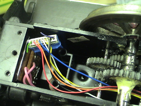 HO
decoders are convenient because they are small. This one is just
stuffed into a pocket near the drawbar. The green and purple leads in
the harness are not used in this decoder and don't go anywhere so I
didn't insulate them. The red and black wires go to the power pickups.
The orange and gray wires go to the motor. The blue wire is about +14
volts. The white and yellow wires are the forward and rearward
headlights. I didn't use the yellow one so it is insulated and stuffed
into the harness with the rest of the wires.
HO
decoders are convenient because they are small. This one is just
stuffed into a pocket near the drawbar. The green and purple leads in
the harness are not used in this decoder and don't go anywhere so I
didn't insulate them. The red and black wires go to the power pickups.
The orange and gray wires go to the motor. The blue wire is about +14
volts. The white and yellow wires are the forward and rearward
headlights. I didn't use the yellow one so it is insulated and stuffed
into the harness with the rest of the wires.
 The
little sound cutoff kludge had been connected to track power, but that
wouldn't work with DCC because there is track power on all the time. It
was reconnected to the motor so that it could detect when the loco was
moving or not.
The
little sound cutoff kludge had been connected to track power, but that
wouldn't work with DCC because there is track power on all the time. It
was reconnected to the motor so that it could detect when the loco was
moving or not.
The headlight had already been converted to a white LED, but it was
connected to the modified smoke circuit. I disconnected it and
reconnected it from the blue wire (+) to the white wire (F0f) retaining
it's 1K ohm current limiting resistor. Now the headlight is directional
and can be turned off remotely.
The DCC conversion on this loco went quite well. It runs more
smoothly than before at low speed because the constant high track
voltage makes the loco less sensitive to variable resistance in the
power pickups, of which this loco has a lot. It still makes the same
gear noise, but that should not have changed. It still pulls it's
assigned consist the same as before. The maximum speed is a little
higher than needed, even at only 16 volts on the track. I'll wait to
see how all of the locos perform at the top end and if they all end up
with too much speed, I'll reduce the track voltage until the slowest
one is fast enough. Then I'll change the decoder parameters of each
loco to set it's individual maximum speed to just what I want.
 The next one that was in line for a DCC
conversion was a 3rd generation Big Hauler, an Emmett Kelly circus
engine. This one has been has been seen before in several places on
this page. A 3rd generation Big Hauler has less gear reduction than the
2nd generation unit. It makes less noise, but it also needs more motor
torque, and therefore draws motor current. The running current is about
1.5 amps which is the limit for the DH123. The stall current is nearly
5 amps, way beyond the DH123's capability. I elected to install a
DG583S decoder which is plenty of capacity for this engine. The
downside of the DG583S is that it is bigger and considerably more
expensive, about $54.
The next one that was in line for a DCC
conversion was a 3rd generation Big Hauler, an Emmett Kelly circus
engine. This one has been has been seen before in several places on
this page. A 3rd generation Big Hauler has less gear reduction than the
2nd generation unit. It makes less noise, but it also needs more motor
torque, and therefore draws motor current. The running current is about
1.5 amps which is the limit for the DH123. The stall current is nearly
5 amps, way beyond the DH123's capability. I elected to install a
DG583S decoder which is plenty of capacity for this engine. The
downside of the DG583S is that it is bigger and considerably more
expensive, about $54.
This installation required access from both the top and the bottom
which made it somewhat more complicated.
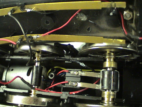
 The
loco used a different method of power pickup so that there isn't a
brass strip running along the side. There are piston contacts and the
first and third driver sets. The motor tabs are used as binding posts
to bring together the wires from the pickups (2 per side) the wire to
the smoke box (1 per side) and a wire to the pilot truck (1 per side).
I also noticed that the bearing support ring for this end of the motor
was missing. I found it stuck in a wad of grease inside the loco.
Apparently, I had dropped it while I was putting in the motor the last
time I was in there.
The
loco used a different method of power pickup so that there isn't a
brass strip running along the side. There are piston contacts and the
first and third driver sets. The motor tabs are used as binding posts
to bring together the wires from the pickups (2 per side) the wire to
the smoke box (1 per side) and a wire to the pilot truck (1 per side).
I also noticed that the bearing support ring for this end of the motor
was missing. I found it stuck in a wad of grease inside the loco.
Apparently, I had dropped it while I was putting in the motor the last
time I was in there.
I removed all four wires from one motor tab and soldered them
together (with the lead from the rear contacts extended to make some
working room) with yet another wire that was directed upwards in the
loco body to provide power to the decoder. I then did the same thing on
the other side. I then cut the tie wrap that was holding the motor in
place and removed the motor. It was easier to solder new wires on the
motor tabs with the motor out of the loco but the main reason for
removing the motor was to reinstall the bearing support ring. I also
soldered the wires to the sound system cutoff kludge and then insulated
the motor tabs. The new motor wires were also directed upwards into the
boiler.
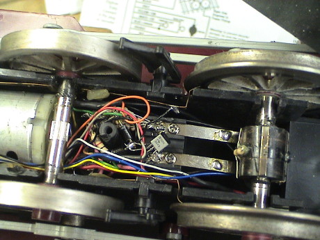
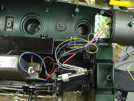
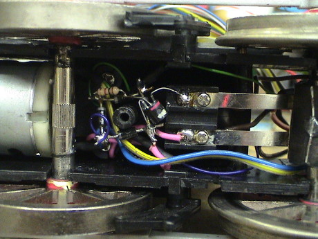 The blue/yellow pair is the motor connection. Not visible in this
photo, there is also a red/black pair for track power. The darker blue
and green wires are the extensions of the wires from the rear pickups.
All of the track power wires are joined up behind the sound system
contacts and insulated with shrink tube. Removal of a bunch of wires
made the area next to the motor much less congested.
The blue/yellow pair is the motor connection. Not visible in this
photo, there is also a red/black pair for track power. The darker blue
and green wires are the extensions of the wires from the rear pickups.
All of the track power wires are joined up behind the sound system
contacts and insulated with shrink tube. Removal of a bunch of wires
made the area next to the motor much less congested.
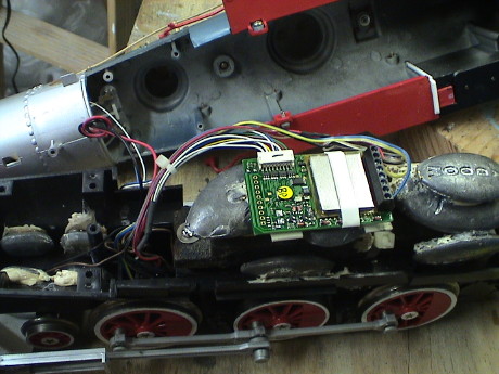 The
decoder is mounted on top of some lead fishing weights. I had to pull
off three 2 oz. weights to make room for the decoder so that it would
not interfere with the inside of the boiler. Two of the missing weights
were attached along the sides of the stack and one was reattached
behind the decoder.
The
decoder is mounted on top of some lead fishing weights. I had to pull
off three 2 oz. weights to make room for the decoder so that it would
not interfere with the inside of the boiler. Two of the missing weights
were attached along the sides of the stack and one was reattached
behind the decoder.
The only function wires that I used were for the headlight, the blue
wire for power and the white wire for the F0f function. As with every
installation of the DG583S that I have done so far, the front headlight
came on only in reverse according to the icon on the throttle. I set
CV29=7 to reverse the normal direction of travel (NDOT) and then
swapped the motor wires so that the loco ran forward when the headlight
was on and the throttle said that the loco should be running
forward.
After reassembly of the loco, it ran fine with no obvious
performance difference except that the low speed stability of the loco
was significantly improved due to the BEMF capability of this
decoder.
 The 3rd generation DCC installation went
ok so I decided to attack the 5th generation Big Hauler next. This one
has had the least modification of any of them but it still has sound
updates and a remounted pilot truck. Power pickup has also been
jumpered from the tender to the loco. This one doesn't draw quite as
much current that the 3rd generation unit, but still too much for an HO
sized decoder so I put another DG583S in this one.
The 3rd generation DCC installation went
ok so I decided to attack the 5th generation Big Hauler next. This one
has had the least modification of any of them but it still has sound
updates and a remounted pilot truck. Power pickup has also been
jumpered from the tender to the loco. This one doesn't draw quite as
much current that the 3rd generation unit, but still too much for an HO
sized decoder so I put another DG583S in this one.
 The
motor mount and gearing are quite different in this loco. The motor
assembly does not come out easily. It looks like there is a pin that
holds the assembly in place. It didn't budge with some moderate tapping
so I elected to rewire the motor in place.
The
motor mount and gearing are quite different in this loco. The motor
assembly does not come out easily. It looks like there is a pin that
holds the assembly in place. It didn't budge with some moderate tapping
so I elected to rewire the motor in place.
 The motor tabs were used for a binding post, but there are only two
wires soldered to each tab. One wire comes from the bottom cover
assembly, the other goes forward to the switch on the smokebox door. I
unsoldered the wires on the top tab to get them out of the way and then
I unsoldered the wires on the bottom tab. The wires going forward can
be pulled off the tabs with a pair of thin needle nose pliers pulling
on the wires as they transit the area under the sound switch contact
strips.
The motor tabs were used for a binding post, but there are only two
wires soldered to each tab. One wire comes from the bottom cover
assembly, the other goes forward to the switch on the smokebox door. I
unsoldered the wires on the top tab to get them out of the way and then
I unsoldered the wires on the bottom tab. The wires going forward can
be pulled off the tabs with a pair of thin needle nose pliers pulling
on the wires as they transit the area under the sound switch contact
strips.
 I spliced the wires back together and insulated them with shrink tube
and pushed the excess up into the boiler.
I spliced the wires back together and insulated them with shrink tube
and pushed the excess up into the boiler.
The motor wires were soldered back on the motor tabs and then the
other end of those wires were pushed back up into the boiler. I
reassembled the bottom of the loco and buttoned it up.
 The installation on the topside was pretty easy with only one
difficulty. Nothing would stick to the cast iron weight so I could not
mount the decoder up there. Even after being cleaned with alcohol,
brushed with a wire wheel and then filed down to bare metal, my foam
tape, hot glue or quick grab glue would not adhere to the cast
iron.
The installation on the topside was pretty easy with only one
difficulty. Nothing would stick to the cast iron weight so I could not
mount the decoder up there. Even after being cleaned with alcohol,
brushed with a wire wheel and then filed down to bare metal, my foam
tape, hot glue or quick grab glue would not adhere to the cast
iron.
I punted and dropped the decoder into a cavity in the frame at the
front. I insulated the connections on the smoke unit because they would
come close to the edge of the decoder.
In the previous installation using the DG583S, I had difficulties
with the headlight not working in the right direction. On a hunch, this
time I wired the front headlight the F0r, the yellow wire for the rear
headlight. Then it worked properly. Further the yellow wire responds to
CV49 which sets up special effects for the FRONT headlight which is
supposed to be on the white wire. Something is wrong in either the
decoder firmware or the cable harness and instructions that define the
front and rear headlight function wires.
I finally got around to converting a 3rd generation
Pennsy Big Hauler to DCC. This one has had most of the standard
modifications already, 4 chuffs/turn, chuff stop, sound board mods and
a weighted front truck.
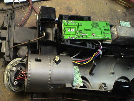 I purchased some MRC AD322
decoders on closeout at $11 each and I had two left and nowhere for
them to go so I stuffed one in the Big Hauler. It was a pretty standard
installation with only the motor and the headlight connected to the
decoder. Except for the physical mounting of the decoder, I used much
the same method as the Emmett Kelly Big Hauler. The decoder is pretty
large but I found a place for it in front of the cast iron weight. The
board is held down with two globs of hot glue at the front. The heat
sink of the regular IC rests on a piece of a coffee stirrer that is
stuck to the weight with double back foam tape. This IC gets pretty hot
in operation so I couldn't just rest it on the tape or it would have
melted right through. Just for safety, I also laid a piece of tape
across the terminals of the smoke unit to act as an insulator although
the decoder board doesn't get very close to it.
I purchased some MRC AD322
decoders on closeout at $11 each and I had two left and nowhere for
them to go so I stuffed one in the Big Hauler. It was a pretty standard
installation with only the motor and the headlight connected to the
decoder. Except for the physical mounting of the decoder, I used much
the same method as the Emmett Kelly Big Hauler. The decoder is pretty
large but I found a place for it in front of the cast iron weight. The
board is held down with two globs of hot glue at the front. The heat
sink of the regular IC rests on a piece of a coffee stirrer that is
stuck to the weight with double back foam tape. This IC gets pretty hot
in operation so I couldn't just rest it on the tape or it would have
melted right through. Just for safety, I also laid a piece of tape
across the terminals of the smoke unit to act as an insulator although
the decoder board doesn't get very close to it.
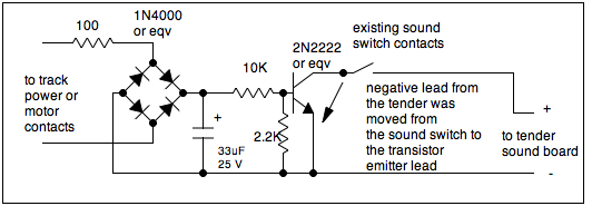 There was one change I had
to make due to an issue with the AD322. This decoder has a much lower
switching frequency than the decoders I used in the other Big Haulers.
Some of this motor noise coupled through the chuff stop circuit and got
onto the chuff sound as an audible buzz. I added a resistor and a
capacitor to filter out this noise. The 100 ohm resistor limits the
peak currents that can charge the capacitor, this is to make the
circuit more friendly to a DCC decoder. The filter capacitor charges up
to the peak motor voltage at the first motor pulse to activate the
circuit as well as filtering off the PWM noise delivered to the motor
by the DCC decoder.
There was one change I had
to make due to an issue with the AD322. This decoder has a much lower
switching frequency than the decoders I used in the other Big Haulers.
Some of this motor noise coupled through the chuff stop circuit and got
onto the chuff sound as an audible buzz. I added a resistor and a
capacitor to filter out this noise. The 100 ohm resistor limits the
peak currents that can charge the capacitor, this is to make the
circuit more friendly to a DCC decoder. The filter capacitor charges up
to the peak motor voltage at the first motor pulse to activate the
circuit as well as filtering off the PWM noise delivered to the motor
by the DCC decoder.
Barry's Big Trains Chassis Upgrade
I had a motor failure of a 3rd generation Big Hauler (the Pennsy
one) and I didn't want to send it to Bachmann because it had been
extensively modified and Bachmann would probably replace it outright. I
would loose my upgrades. So instead, I asked Barry of Barry's Big Trains if he had any
motors. He did and sold me one for $5 plus shipping. I used that motor
to fix the Big Hauler. Then Barry kept asking me if I had an "Annie"
version and I said that I didn't. I was far too dense to realize that
he wanted to send me a whole upgrade for evaluation and review. He sent
it to me anyway. Then I had one of his famous upgrades and no broken
locos to install it into. What to do? I am a firm believer in the "if
the damn thing works at all, don't mess with it" philosophy. I mess
with stuff if it doesn't work right. If it's running to my
satisfaction, I leave it alone. All four of my track powered Big
Haulers were in that camp (the Pennsy had just been fixed).
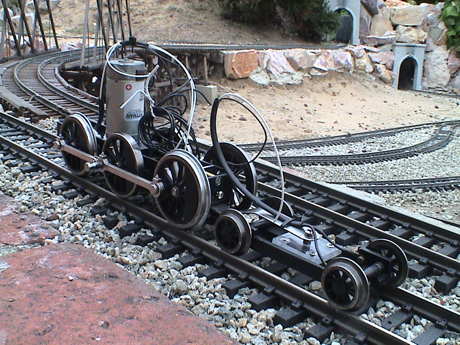 This is the chassis that Barry sent.
This is a chassis intended for the Bachmann "Annie." It is a MAJOR
upgrade from ANY production Big Hauler. It has a REAL motor (a
Pittman), heavy duty gears, piston type power pickups, a magnetic chuff
sensor and a rocking front driver. The rocking driver provides a true 3
point suspension and improves tracking significantly. It also has his
replacement front truck with power pickups. Barry says that the whole
thing (less motor) is warranted for HIS lifetime.
This is the chassis that Barry sent.
This is a chassis intended for the Bachmann "Annie." It is a MAJOR
upgrade from ANY production Big Hauler. It has a REAL motor (a
Pittman), heavy duty gears, piston type power pickups, a magnetic chuff
sensor and a rocking front driver. The rocking driver provides a true 3
point suspension and improves tracking significantly. It also has his
replacement front truck with power pickups. Barry says that the whole
thing (less motor) is warranted for HIS lifetime.
Barry also makes upgrades for conversion of a Big Hauler to a 2-8-0
and he is working on kits for upgrading the Lionel Atlantic, the
Bachmann K-27 and the Bachmann Connie.
He sent me this thing and I feel that I owe him a report for his
effort. So which working Big Hauler do I rip apart?
This is my
very first large scale loco, a 2nd generation Big Hauler. I got it at
Christmas in 1990 as part of a Costco set. This is the train that sunk
my future by getting me into large scale trains in the first place. It
whines a bit when it runs, but it has been running with few serious
problems for 20 years. I expect that it will go much longer. Even with
the noise, I still like it a lot, it runs very well and I didn't want
to mess with success.
This 3rd generation Big Hauler came a year or so later, also in a
Costco set. It gave me quite a bit of trouble, but eventually I got it
running properly. It doesn't get much run time but it runs and I
elected not to tear into it either.
This one actually belongs to my son, Charlie. He got
it from Christmas in the late 90's sometime. This is the one that
recently ate it's motor after some extended running. It's been fixed so
I didn't want to tear into it either.
The
Chattanooga Choo Choo arrived, also in a Costco Christmas set, in about
2000. It is a 5th generation unit and has run quite well from the
beginning. I didn't want to tear into this one either.
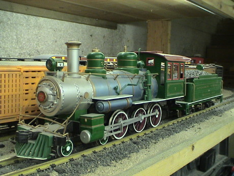 Then there is
this one. This is 1st generation RC Big Hauler that belongs to my
oldest son, Richard. He also got it for Christmas in 1990 when he was
just seven years old. The sets were being sold for $50 at the time at
Toys-R-Us. This set proved less frustrating than an HO train set he got
from his grandfather the year before (the HO stuff still lives, see the
GIRR HO page).
Then there is
this one. This is 1st generation RC Big Hauler that belongs to my
oldest son, Richard. He also got it for Christmas in 1990 when he was
just seven years old. The sets were being sold for $50 at the time at
Toys-R-Us. This set proved less frustrating than an HO train set he got
from his grandfather the year before (the HO stuff still lives, see the
GIRR HO page).
The engine actually still sort of runs and the transmitter that goes
with it also still works. However, the engine doesn't run very well.
After running on metal track for several years, the plastic driver
flanges roughed up and the thing would climb the rails and derail. I
replaced the plastic drivers with metal ones and it didn't derail, but
there was some kind of problem with the radio link. The engine would
stop and try to back up when running over turnouts. I never did figure
out how to fix that except to keep the transmitter within a few feet of
the loco so it just sat in the engine yard for 15 years or so. I also have
most of the bits and pieces of two other RC Big Haulers (one green like
that one and one circus engine).
This is what I needed, a nearly useless loco. I also like the paint
job and it is lettered for ATSF. If I could fit Barry's upgraded
chassis under this loco, it would probably fit anywhere. The loco has
the typical Bachmann chuff only sound system (on a board in the
smokebox) which will get ripped out and reinstalled in the tender. The
tender has metal wheels too so I can add power pickups to the tender if
necessary. I have one spare DG583S DCC decoder in stock which should
run Barry's chassis just fine.
I don't have the room for another running Big Hauler at the GIRR
Mountain Division so I'm going to move this one to the GIRR where it
will run outside, sometimes in some heat. Barry's chassis will be more
suitable there than in the sheltered and cool environment of the
Mountain Division.
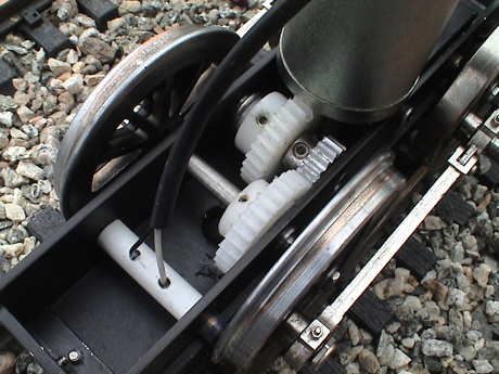 This is the gear train of the BBT
chassis. Barry normally uses the drivers from the target conversion
loco, trues them and them mounts them to a new axle, properly
quartered. This kit came with wheels.
This is the gear train of the BBT
chassis. Barry normally uses the drivers from the target conversion
loco, trues them and them mounts them to a new axle, properly
quartered. This kit came with wheels.
The Pittman motor draws about 300 mA running free on the bench and 8
amps at a hard stall at 20 volts. The motor is wired to the power
pickups on the loco as delivered so it will run by itself.
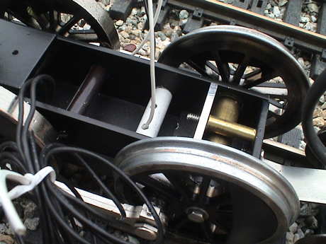 The white cylinder is a pair of
piston contacts for the front driver. The black cylinder behind it is
the reed switch for the chuff. There are four magnets imbedded in the
wheel, one is just barely visible above the chassis. The black wires in
the foreground are the wires to the reed switch. The assembly at the
front is the rocking axle bushing.
The white cylinder is a pair of
piston contacts for the front driver. The black cylinder behind it is
the reed switch for the chuff. There are four magnets imbedded in the
wheel, one is just barely visible above the chassis. The black wires in
the foreground are the wires to the reed switch. The assembly at the
front is the rocking axle bushing.
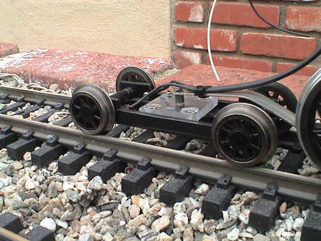 On the chassis he sent me, the pilot
truck is already mounted. It has it's own power pickups but they need
to be wired in.
On the chassis he sent me, the pilot
truck is already mounted. It has it's own power pickups but they need
to be wired in.
Barry provides extensive instructions for how to cut down a track
powered or RC Big Hauler to integrate with his chassis. Some trimming
needs to be done to reattach the hook for the tender and for the stock
Bachmann pilot truck if Barry's truck isn't used. The work isn't hard,
but the instructions need to be followed closely.
The first thing that I did was run the chassis on the track on DC
and it ran fine. The track was horribly dirty as it had not been
cleaned in more than a month as I had been traveling and the trains
hadn't been running. With only 4 wheels picking up power, it sputtered
a little, but it wasn't bad. Then I cleaned a section and it didn't
sputter at all on that section. I then wired the pilot truck in and did
a test install of a DCC decoder, a DG583S. This worked out fine and the
loco ran well even on the dirty track.
Then I sat down with the instructions trying to figure out what I am
going to have to do to hack up the Big Hauler. The basket case shell
that I have is too much of a basket case to actually use, many of the
detail parts are missing from the shell. Unless I find some serious
issue, I am going to cut up the "frame" part of a basket case unit and
then mount the good shell to that assembly.
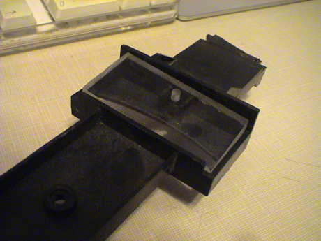 Barry included a
piece of clear plastic with the kit. A handwritten note indicated that
it was a stiffener for the area that had the old pilot truck. The
curved slot is so long that it weakens the whole assembly. The new
piece is supposed to fit in there and be securely glued down so that
the impact of the slot is negated.
Barry included a
piece of clear plastic with the kit. A handwritten note indicated that
it was a stiffener for the area that had the old pilot truck. The
curved slot is so long that it weakens the whole assembly. The new
piece is supposed to fit in there and be securely glued down so that
the impact of the slot is negated.
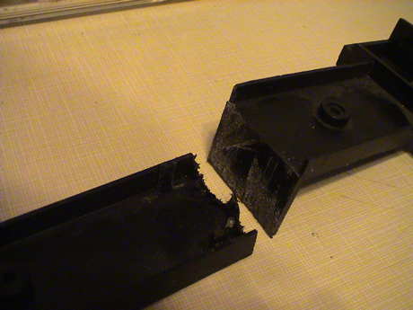 The lower cover is hacked into three pieces per the drawings that came
with the upgrade kit. In this photo, the forward part of the lower
cover is cut off. It will be screwed back to the front of the BBT
chassis.
The lower cover is hacked into three pieces per the drawings that came
with the upgrade kit. In this photo, the forward part of the lower
cover is cut off. It will be screwed back to the front of the BBT
chassis.
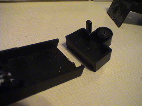 Similarly, the rear
extension is cut off the lower cover and bolted to the rear of the BBT
chassis. Eventually, when the chassis assembly is hacked and fitted
into place, two screws will go through these extensions and mate to the
Bachmann chassis to secure the BBT chassis to the Bachmann chassis.
Similarly, the rear
extension is cut off the lower cover and bolted to the rear of the BBT
chassis. Eventually, when the chassis assembly is hacked and fitted
into place, two screws will go through these extensions and mate to the
Bachmann chassis to secure the BBT chassis to the Bachmann chassis.
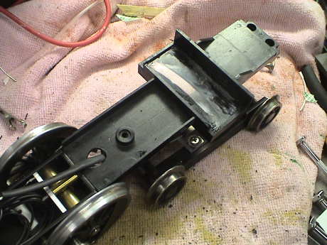 There
was one hang up with the stiffener piece that Barry supplied. It blocks
the curved slot so that it is no longer easy to route the power pickup
wires from the pilot truck back into the loco. I drilled a 3/8" hole in
the Bachmann pilot part to clear the wire.
There
was one hang up with the stiffener piece that Barry supplied. It blocks
the curved slot so that it is no longer easy to route the power pickup
wires from the pilot truck back into the loco. I drilled a 3/8" hole in
the Bachmann pilot part to clear the wire.
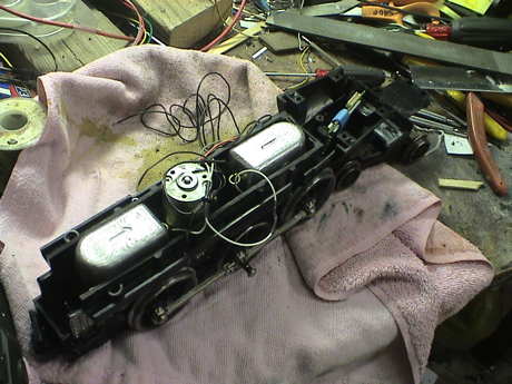 The chassis piece
is severely cut down per the BBT instructions. The lower parts are
removed to clear the axles and pickups. I used and RC Big Hauler
chassis so that sides of the battery compartment are cut down. Then a
big hole is cut through the bottom of the piece to clear the motor.
This piece then fits over the motor and onto the BBT chassis. Two
screws coming up from the bottom hold the whole thing together.
The chassis piece
is severely cut down per the BBT instructions. The lower parts are
removed to clear the axles and pickups. I used and RC Big Hauler
chassis so that sides of the battery compartment are cut down. Then a
big hole is cut through the bottom of the piece to clear the motor.
This piece then fits over the motor and onto the BBT chassis. Two
screws coming up from the bottom hold the whole thing together.
Apparently, there are two flavors of chassis in the RC Big Hauler.
The one I cut up didn't have the bosses for the brake shoes. The other
two did. Therefore, I didn't use the brake shoes.
The hacking on the chassis assembly is what took the longest amount
of time. I used a Dremel tool with a cutoff wheel to make the side
cuts. I used a razor saw for part of it but my arm was getting tired.
The Dremel was a bit slower, but less work. For the cutout to clear the
motor I used the Dremel with a small milling bit and just gouged it
out.
Barry recommends added 4 to 5 lbs of weight to the loco. I elected
to add 2 lbs of fishing weights inside the chassis assembly. If it
isn't enough, I have two more weights that I can stack on top of those.
They are held in with fillets of hot glue (applied after the photo was
taken).
The Digitrax DG583S DCC decoder has been placed in the chassis right
under where the air tanks will be. There is plenty of room for it and
all the wiring is easy to get to. I am going to use a 6 conductor
harness and connector to connect to the tender. Two wires will be
reserved for power pickups on the tender if I need them. Two will be
used by the chuff trigger that BBT provides. The other two are for the
rear headlight which Big Haulers do not typically have, but I am going
to wire an LED into each of the existing housings.
At this point, I haven't touched the loco that will surrender it's
shell and sound board to this conversion.
I have wired the 6 conductor cable to the loco. For my own records,
this is the pinout.
BBT Big Hauler Conversion Tender Connect
Harness
| Wire Color |
Function |
| Black |
Left Rail |
| Gray |
+Common (blue wire) |
| Brown |
Sound Trigger |
| Green |
Sound Trigger Return |
| Yellow |
Rear Headlight |
| Red |
Right Rail |
The old RC Big Hauler surrendered it's shell, steam chest, pilot,
and drive rods to the conversion. It actually had a headlight, a 9 volt
55 mA bulb, so I used it with a 200 ohm series dropping resistor. If it
eventually isn't bright enough or fails, I'll wire in an LED. The final
assembly went smooth enough, the shell mounts the same way that it used
to. I did patch up some broken detail with gel CA and it's still
missing it's bell although the bell harp is still there, but the loco
part is done. The black wheels don't look too bad under the green loco.
If it bothers me, I can paint them later.
As indicated in the BBT instructions, I had to add some spacers
between the connecting rods and drive rods. The crankpin on the center
drivers are pretty long so that the drive rods can clear the crankpin
on the front driver. I added a 0.225" long piece of 0.25" OD brass tube
to each side as a spacer so that the drive rods are positioned parallel
to the track.
Next, the tender. The RC Big Hauler's sound board is part of the RC
control board that is still attached to the old frame. There are
instructions on how to reuse it as a stand alone analog sound generator
earlier at my Better
Bachmann Sound for Under a Buck page. I'll reuse the speaker that
is already in the tender and wire in a 9 volt battery to power the
board. It'll use a battery clip as the stuff that is usually in a Big
Hauler tender to deal with the battery isn't there in the RC
version.
The tender has San-Val metal wheels and I have included track pickup
wires in the 6 conductor harness but I won't add pickups to the tender
until I determine that they are necessary.
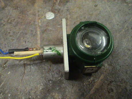 The rear headlight
assembly never had anything in it. I elected to install an LED. The
headlight is cast with a horizontal split line. To gain access, the top
half needs to be pried off to break some glue joints. I drilled up
through the screw hole in the bottom for wire access. It sticks well
enough in it's mount that it doesn't really need the screw. The 5 mm
warm white LED leads were formed to allow the LED to face out of the
lens. The leads were separated with a toothpick rammed up the access
hole. This also allowed me to adjust the position of the LED after I
had reassembled the headlight and it insulated the LED leads. An
820Ω resistor is used to current limit the LED at 20 mA when run
from a DCC track voltage of 22 VRMS.
The rear headlight
assembly never had anything in it. I elected to install an LED. The
headlight is cast with a horizontal split line. To gain access, the top
half needs to be pried off to break some glue joints. I drilled up
through the screw hole in the bottom for wire access. It sticks well
enough in it's mount that it doesn't really need the screw. The 5 mm
warm white LED leads were formed to allow the LED to face out of the
lens. The leads were separated with a toothpick rammed up the access
hole. This also allowed me to adjust the position of the LED after I
had reassembled the headlight and it insulated the LED leads. An
820Ω resistor is used to current limit the LED at 20 mA when run
from a DCC track voltage of 22 VRMS.
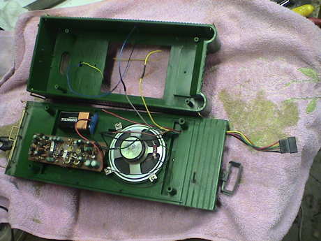 The whole RC Big Hauler
receiver/motor controller/sound board has been remounted in the tender.
Two traces have been cut so that only the sound section is powered. I
am using the stock speaker.
The whole RC Big Hauler
receiver/motor controller/sound board has been remounted in the tender.
Two traces have been cut so that only the sound section is powered. I
am using the stock speaker.
The tender had an LGB knuckle coupler on it as it came from the GIRR
Mtn Div. I removed it and installed a Kadee #831.
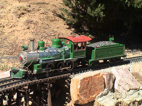 I did a test run this
afternoon. It went pretty well but there are some issues. First, the
BBT sound trigger switch shorted closed after the loco had run for
about 20'. I'll need to take the loco back apart to access it. Second,
I forgot to add my chuff cutoff circuit. Third, it is clear that the
loco doesn't have enough weight. It has way more power than it has
traction. Barry's recommendation of 4 to 5 lbs is probably closer to
correct. While I have it open, I'll add some more. Fourth, the wimpy
incandescent headlight has to go. The LED rear headlight is so much
brighter that I'll need to do somewhat the same modification to it too.
However, it ran and tracked well. I did get some derailments, but only
because the loco was continually running over dried ivy leaves, stems
and twigs. When those were finally swept off the track, it didn't have
any more problems. The track was really dirty and the loco was
hesitating a bit but after I dragged and Aristo track cleaning car
around a few times, that went away too.
I did a test run this
afternoon. It went pretty well but there are some issues. First, the
BBT sound trigger switch shorted closed after the loco had run for
about 20'. I'll need to take the loco back apart to access it. Second,
I forgot to add my chuff cutoff circuit. Third, it is clear that the
loco doesn't have enough weight. It has way more power than it has
traction. Barry's recommendation of 4 to 5 lbs is probably closer to
correct. While I have it open, I'll add some more. Fourth, the wimpy
incandescent headlight has to go. The LED rear headlight is so much
brighter that I'll need to do somewhat the same modification to it too.
However, it ran and tracked well. I did get some derailments, but only
because the loco was continually running over dried ivy leaves, stems
and twigs. When those were finally swept off the track, it didn't have
any more problems. The track was really dirty and the loco was
hesitating a bit but after I dragged and Aristo track cleaning car
around a few times, that went away too.
21 Aug 10
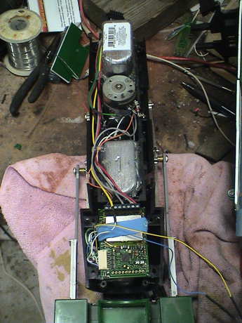 I tested the sound
trigger switch this morning and it was still stuck. A simple tap with a
screwdriver on the chassis was enough to shock the trigger and cause it
to open again. It is pretty clear that the current drawn by the sound
system was welding the contacts. The sound system current is pretty
low, about 60 mA, but there might be a spike that is higher. The
47µF capacitor that I sometimes install on these things isn't
there on this one. I installed a 47Ω resistor in series with the
sound system trigger input to provide a little current limiting and
gave it a few minutes test on the bench. The problem appears to be
gone.
I tested the sound
trigger switch this morning and it was still stuck. A simple tap with a
screwdriver on the chassis was enough to shock the trigger and cause it
to open again. It is pretty clear that the current drawn by the sound
system was welding the contacts. The sound system current is pretty
low, about 60 mA, but there might be a spike that is higher. The
47µF capacitor that I sometimes install on these things isn't
there on this one. I installed a 47Ω resistor in series with the
sound system trigger input to provide a little current limiting and
gave it a few minutes test on the bench. The problem appears to be
gone.
I installed one of the chuff stopper circuits that is described
earlier in this page. It is soldered onto the motor leads so that it
detects when the DCC decoder has stopped the loco.
Another 1 lb weight is attached on top of the one in the rear. At
the front, the existing weight was offset a little behind the first
driver so I attached another 1 lb weight forward of the driver in an
attempt to get the sum of the weights balanced above the first driver.
It is mounted where the DCC decoder used to be, below the DCC decoder
in the photo. Eventually, I moved the decoder to mount with foam tape
on top of the original forward weight. The decoder was just a little
too wide to allow the loco to be reassembled easily.
The headlight was modified to be an LED just like the rear one. It
is mounted as described above in this page. It also uses an 820Ω
current limiting resistor so that it draws 20 mA.
Unless I run into further difficulties, I think that the BBT upgrade
installation is complete.
I ran my more or less standard Tractive Effort Tests and it
came out about right. On my ruling grade, it pulls 12 heavy cars with
just a little slipping. Running light, it draws 600 mA. Either pulling
the 12 cars or restrained so that it is slipping, it pulls 1.4 amps.
This with DC on the track.
I added power pickups to the tender lead truck using the brass strip
method described in the power pickup section of this page. I also added
a sound power switch since I was in there already. It probably doesn't
need it, the Bachmann boards draw very little current when idle but I
put it in anyway.
Sep 3, 2010
I took the BBT upgraded Big Hauler to the GIRR Mtn Div for testing
on tight radius (4' diameter, R1) track. I expected it to do well, it
didn't. It derailed on the first turn. The pilot truck went first and
took the rest of the loco with it.
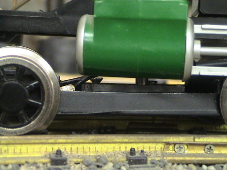 Unfortunately,
I didn't get a photo of the truck in it's original state. The problem
is that it was mounted too far to the rear and the front wheel was
hanging up on the cylinder head in the tight curves. This lifted the
rear axle of the pilot truck off the track and it derailed
immediately.
Unfortunately,
I didn't get a photo of the truck in it's original state. The problem
is that it was mounted too far to the rear and the front wheel was
hanging up on the cylinder head in the tight curves. This lifted the
rear axle of the pilot truck off the track and it derailed
immediately.
After inspecting the assembly, I found two problems. First, the
swing arm wasn't quite long enough so that the truck was too far
rearward by about 1/4". The truck should be centered on the cylinder
assembly like the photo. Also, the plastic insulator in the center was
not flopping around like it was supposed to.
I removed the truck from the mounting bracket and then removed the
plastic insulator. The countersunk holes were not drilled in exactly
the right spot and where the hole was narrowest at the bottom, the
plastic insulator was hanging up on the screw threads. A quick file job
to open the holes a little fixed that.
Then I drilled and tapped a new #4-40 pivot hole for the truck 1/4"
behind the original one and remounted the truck in the new hole. This
improved the derailment problem but didn't entirely fix it. Now I could
see that the rear axle was not turning while in tight curves. There
were two causes for that.
First, one of the wheelsets on the rear axle appeared to have some
glue or something on the axle where it rotated inside the truck. This
was hanging it up. Some file work took that off and it got better but
it was still not well and the truck still tended to derail at the rear
axle.
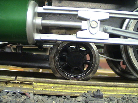 The
way that the pilot truck bracket was bent, it was applying a rotational
force that pitched the truck upward to the rear. This tended to lift
the rear axle off the track a little and it didn't get enough friction
to turn. I rebent the bracket such that it was closer to parallel with
respect to the track, as shown in the photo, instead of canted downward
to the front. Both bends were too tight and needed adjustment. THEN
both axles would turn and the pilot truck did not derail.
The
way that the pilot truck bracket was bent, it was applying a rotational
force that pitched the truck upward to the rear. This tended to lift
the rear axle off the track a little and it didn't get enough friction
to turn. I rebent the bracket such that it was closer to parallel with
respect to the track, as shown in the photo, instead of canted downward
to the front. Both bends were too tight and needed adjustment. THEN
both axles would turn and the pilot truck did not derail.
The loco did have some difficulties on the tight radius LGB and
Aristo turnouts, it tended to bump over the frogs. This is because the
driver flanges are a little smaller than the stock flanges. This was
probably done to make it look better. However, in flange bearing frogs,
the wheel tends to drop a little in the frogs. Just don't take the low
speed turnouts at high speed and it'll do better. The original Big
Hauler driver flanges are almost the same size as the ones on the pilot
wheels. After Barry's modifications, I think that they are a little
smaller.
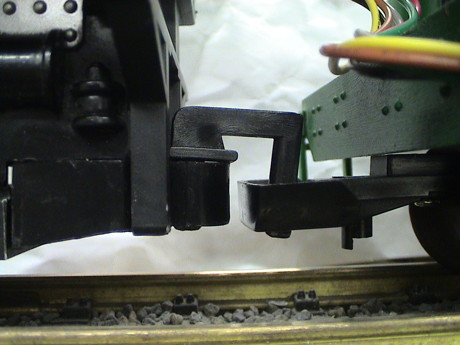 Something
I had never noticed before was that the hook for the tender seemed to
be a little high. I knew that that would be a problem at one spot on
the GIRR Mtn Div where there is an abrupt vertical gradient (it's been
there since day 1 and would be hard to fix). The front of the engine
will dip downward when it was on the grade and the tender was still on
the flat. The hook moved upward and the tender would either disconnect
or almost disconnect.
Something
I had never noticed before was that the hook for the tender seemed to
be a little high. I knew that that would be a problem at one spot on
the GIRR Mtn Div where there is an abrupt vertical gradient (it's been
there since day 1 and would be hard to fix). The front of the engine
will dip downward when it was on the grade and the tender was still on
the flat. The hook moved upward and the tender would either disconnect
or almost disconnect.
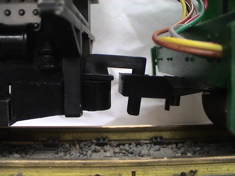 I could
not determine if the loco was actually higher than it used to be but I
suspect that this is the case. In any event, I could either try to
remount the hook part lower or adjust the loop. It was easiest just to
put a hot air gun on the tender truck coupler tang for about 10 seconds
and to form it upward until the loop almost touched the tender frame.
This resulted in plenty of engagement and the problem was solved.
I could
not determine if the loco was actually higher than it used to be but I
suspect that this is the case. In any event, I could either try to
remount the hook part lower or adjust the loop. It was easiest just to
put a hot air gun on the tender truck coupler tang for about 10 seconds
and to form it upward until the loop almost touched the tender frame.
This resulted in plenty of engagement and the problem was solved.
Sep 4, 2010
I am still having some difficulty
with the chuff switch. The black cylinder is the reed switch for the
chuff. Some days it works properly, some days it doesn't. On the bad
days, the sound system will chuff only three or even two beats per
turn.
BBT has mounted the chuff switch crossways to the chassis so the
magnets embedded in the left center driver are lined up with the end of
the reed switch. The switch is least sensitive in this position and
probably needs to be remounted. To do that, I'll have to remove the
shell and peel out the weight behind the front driver axle so that I
can get to the switch. The switch probably should be mounted against
the chassis wall, near the top of the frame, so that the center of the
switch is nearest the arc of the magnets and that the path of the
magnets is nearly perpendicular to the switch. There is marginally
enough room to mount the switch on the outside of the frame, on the
bottom. However, this is not a good plan. When the magnet movement is
parallel to the switch axis, it may bounce and make two beats where
there should be only one. Mounting the switch inside above the existing
switch, the magnet path will be nearly perpendicular to the switch
body. However, then the switch would be further away from the magnets
and there is no assurance that the change would work better.
Another possible option is to remove the driver with the embedded
magnets and see if I can find some stronger magnets that would fit in
the holes that BBT drilled. There isn't room between the existing
magnets and the frame to place a small magnet on the end of the
existing ones. There MIGHT be room to shim the existing magnets outward
just a little. This might be easier than remounting the reed
switch.
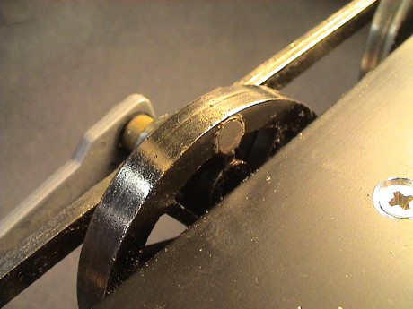 However all
this seems like a lot of work. When only one chuff isn't working, then
that magnet is probably further from the switch. I identified which
magnet it was relative to the crankpin and looked at it's position
relative to the other magnets. It was the one that had the least
extension from the wheel so it was furthest from the switch. I then
decided to try slightly moving the switch.
However all
this seems like a lot of work. When only one chuff isn't working, then
that magnet is probably further from the switch. I identified which
magnet it was relative to the crankpin and looked at it's position
relative to the other magnets. It was the one that had the least
extension from the wheel so it was furthest from the switch. I then
decided to try slightly moving the switch.
The switch is mounted in a hole in the left side of the frame and
protrudes somewhat. The other end is restrained by it's leads which are
fed out a slot to the outside and then right back in another adjacent
slot. I found that by inserting a small screwdriver under the wires
that were outside the frame on the engineer's side, I could pull a
little wire back out the 2nd slot. Then I could use the same
screwdriver to push the switch to the fireman's side by pressing gently
into the 1st slot. This pushed the switch outward toward the wheel with
the magnets. Then the magnet that stuck out the furthest would hang on
the switch. The solution there was to file the high spot and smooth out
the edges of the magnets and the glue that was holding them in place so
that all of them were flush or nearly flush to the wheel. Then I could
push the switch out to where is almost touched the one that was still a
small lump on the wheel. Using a toothpick, I placed a drop of gap
filling CA to bridge the gap between the switch housing and the frame.
There is only a little bit there. I want to be able to break that joint
later if necessary and even a small amount of CA will hold the switch
in position. Now there is a minimal gap between all four magnets and
the switch and it chuffs four times per turn. The bearings that BBT
uses hold the wheel very tightly in position so that movement of the
wheel itself is very small. In any event, with the magnets flush to the
wheel, there is nothing for the switch to hang up on even if it drags a
little sometimes. We'll see how this adjustment holds up over time. If
this doesn't work, I can still try the other, more invasive,
methods.
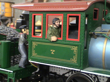 After all the
work I'd done on this loco, I realized that it didn't have a crew. A
little scrounging through my box of figures yielded these two. The Big
Hauler cab doesn't have a lot of room in it but this figure made an
acceptable engineer and he actually fit. The fireman is a stock
Bachmann figure that comes with some of their locos.
After all the
work I'd done on this loco, I realized that it didn't have a crew. A
little scrounging through my box of figures yielded these two. The Big
Hauler cab doesn't have a lot of room in it but this figure made an
acceptable engineer and he actually fit. The fireman is a stock
Bachmann figure that comes with some of their locos.
Update 2 Nov 12
It's been 2 years and the loco is still running fine. I used it today to pull a modified Aristo track cleaning car as the layout hadn't been run all summer. Even on track that hadn't seen any cleaning in months, the power pickup was good enough to do the job. However, the loco isn't very good at sweeping leaves. Locos with more weight on the lead truck will run over and crush dried ivy leaves, this one will not. The pilot truck derails on leaves that are not swept off by the pilot. Once the leaves were cleaned up manually, it ran fine. I did find that it was heavy enough to spread the rails on sections with rotted Aristo tie strips and it would simply sink into the track at those spots and derail. The tie strips need to be replaced.
[ Top ] [ Home ] [ Up ] [ Previous Page ] [ Next Page ]
This page has been accessed  times since 17 Dec 1997.
© 1997-2012 George Schreyer
Created Oct 5, 1997
Last Updated November 2, 2012
 5 Dec 08
 14 Aug 10