 21 Oct 09 21 Oct 09
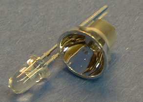 Light
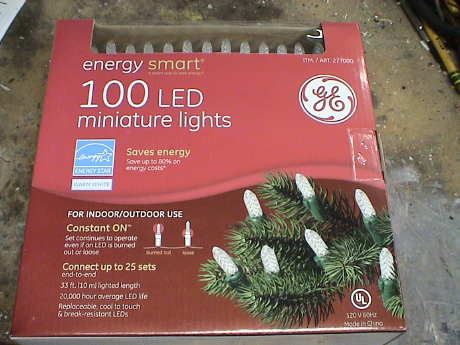
Emitting Diodes (LED) have recently become available
that are both white and bright, so bright that they seriously
compete with incandescent lamps in lighting applications. They can
be pretty expensive as compared to a GOW (Grain Of Wheat) lamp but
draw much less current and project a fairly well focused beam. LED
prices are coming down, some can be found for $0.50 to $1. The
diode in the photo came with a neat little reflector that tends to
sharpen the beam a little but doesn't seem to add much to the
overall intensity.
Light
Emitting Diodes (LED) have recently become available
that are both white and bright, so bright that they seriously
compete with incandescent lamps in lighting applications. They can
be pretty expensive as compared to a GOW (Grain Of Wheat) lamp but
draw much less current and project a fairly well focused beam. LED
prices are coming down, some can be found for $0.50 to $1. The
diode in the photo came with a neat little reflector that tends to
sharpen the beam a little but doesn't seem to add much to the
overall intensity.
When run within their ratings, they are more reliable than lamps as well. LEDs are now being used in automotive and truck tail lights and in traffic signal lights. You will be able to detect them because they look like an array of point sources and they go on and off instantly as compared to conventional incandescent lamps.
For those who are technically inclined, a good summary of LEDs can be found at Wikipedia.
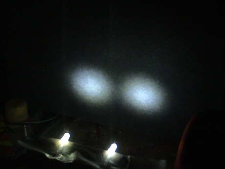
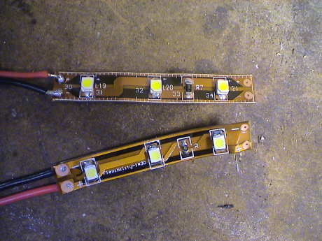
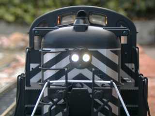
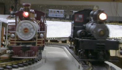 When used as a locomotive
headlight, the effect is quite good. The Big Hauler on the left has
a Radio Shack 12v 60 mA Grain-Of-Wheat bulb running at its ratings.
The Shay on the right has the stock Bachmann bulb that came on the
early production Shays, later Shays have a much more wimpy standard
yellow LED as a headlight. You can see that the Big Hauler light is
not very bright as compared to the Shay.
When used as a locomotive
headlight, the effect is quite good. The Big Hauler on the left has
a Radio Shack 12v 60 mA Grain-Of-Wheat bulb running at its ratings.
The Shay on the right has the stock Bachmann bulb that came on the
early production Shays, later Shays have a much more wimpy standard
yellow LED as a headlight. You can see that the Big Hauler light is
not very bright as compared to the Shay.
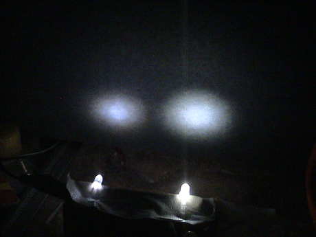
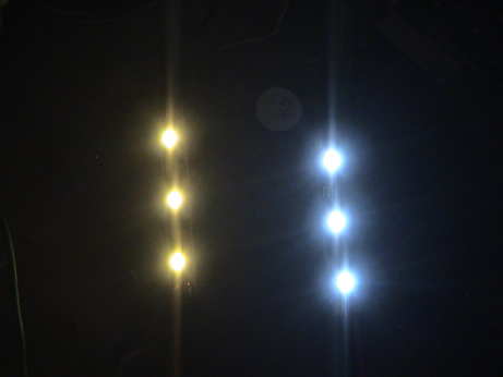
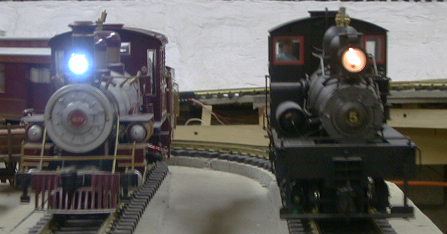 This photo shows the same two
engines after a bright white LED has been installed in the Big
Hauler. The LED is running at its rated 20 mA vs the 60 mA that the
old GOW bulb took. Now compare the brightness of the two locos
using the Shay as a reference to see how much brighter the white
LED is.
This photo shows the same two
engines after a bright white LED has been installed in the Big
Hauler. The LED is running at its rated 20 mA vs the 60 mA that the
old GOW bulb took. Now compare the brightness of the two locos
using the Shay as a reference to see how much brighter the white
LED is.
The LED produces a tight bright beam that goes further down the track than most incandescent lamps. In a dark environment, it is bright enough to cast shadows more than 10 feet away. In the indoors environment, the LED might be too bright. These trains run at eye level and when the beam sweeps across my eyes, it is blinding.
The viewing angle and the brightness of LEDs vary inversely. A wider angle will result in lower brightness in any given direction as the total light output of the LED is spread over a larger area. For headlight applications, a 20° viewing angle is appropriate. This is not the tightest angle available, there are 10 ° LEDs for sale. The narrow angle LEDs produce the most intense beam in front of the loco with a loss of intensity at off angles. Intensity is rated in candlepower, a typical tight beam LED runs between 4000 to 24000 mcd. The size and shape of the diode package determines the minimum beamwidth, a larger package with a larger lens can focus a tighter beam. For most large scale headlight applications, a 5 mm diode package is adequate. There are 10 mm packages available that will produce a tighter beam, but a 10 mm (0.4") LED is really too large to mount on a loco. There are also 3 mm LEDs available for packaging in tight spots.
This tight beam aspect of many of the white LEDs has a downside also. The tighter the LED beam, the dimmer it will appear when viewed off angle. Some of them have such a well formed beam that they are hardly visible at all at angles between 30 and 80°. At almost 90° they have a sidelobe and are visible again. A regular frosted diffuse LED, such as Bachmann and Aristo use, may appear brighter than a tight beam white LED in the daylight when viewed off angle because they spray light in all directions. However, the diffused wide angle LEDs have no hope of casting any sort of a beam in dim light or darkness. White LEDs with a different shaped (usually smaller) lens will have a wider viewing angle, but do not form as tightly a focused beam. They light up the general area in front of the loco instead of casting a beam down the track. There really is no free lunch.
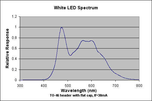 LEDs are
monochromatic (one color) devices. The color is determined by the
bandgap of the semiconductor used to make them. Red, green, yellow
and blue LEDs are fairly common. White light contains all colors
and cannot be directly created by a single LED. The most common
form of "white" LED really isn't white. Its an Indium Gallium
Nitride blue LED coated with a phosphor that, when excited by the
blue LED light, emits a broad range spectrum that in addition to
the blue emission makes a fairly white light. The actual light has
a blue cast and is similar in color to a mercury vapor street lamp.
On the curve shown, the peak at the left is the shortest wavelength
blue light from the LED. The lump of emission to the right is the
longer wavelength emission of the phosphor. There are other types
of "white" LEDs that are made from several different LED chips of
different colors assembled into one package. These have not been
particularly successful as they tend to change color depending on
viewing angle and their color balance is not real good at best.
LEDs are
monochromatic (one color) devices. The color is determined by the
bandgap of the semiconductor used to make them. Red, green, yellow
and blue LEDs are fairly common. White light contains all colors
and cannot be directly created by a single LED. The most common
form of "white" LED really isn't white. Its an Indium Gallium
Nitride blue LED coated with a phosphor that, when excited by the
blue LED light, emits a broad range spectrum that in addition to
the blue emission makes a fairly white light. The actual light has
a blue cast and is similar in color to a mercury vapor street lamp.
On the curve shown, the peak at the left is the shortest wavelength
blue light from the LED. The lump of emission to the right is the
longer wavelength emission of the phosphor. There are other types
of "white" LEDs that are made from several different LED chips of
different colors assembled into one package. These have not been
particularly successful as they tend to change color depending on
viewing angle and their color balance is not real good at best.
There is a claim that these white LED's have a limited life. After 1000 hours or so of operation, they tend to yellow and dim to some extent. Running the LEDs at more that their rated current will certainly accelerate this process.
The phosphor type of LED was developed by Nichia in Japan. I do not know if other manufacturers are making this type of LED now, but for some time, ALL the white LEDs of this process that were sold anywhere were made by Nichia.
I finally burned through my original stock of white LEDs (the ones in the lead photo) so I needed more. In July 2008, I purchased three kinds of white LED from TheLEDLight.com to see what has changed. For the evaluations in the following photos, the diodes were wired in series so they all were running exactly the same current.
| Color | Size | Part Number | Viewing Angle | Intensity (mcd max) | Cost (ea) |
|---|---|---|---|---|---|
| White | 5 mm | LED5 20-25DG WH | 20+° | 21,000 | $1.00 |
| Warm White | 5 mm | LED5 20DG WWY | 20° | 11,000 | $1.00 |
| White | 5 mm | LED5 30DG WH | 30° | 5,500 | $0.50 |
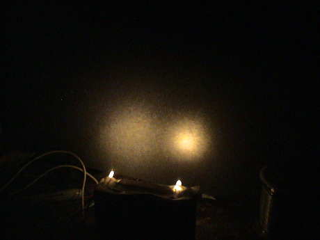
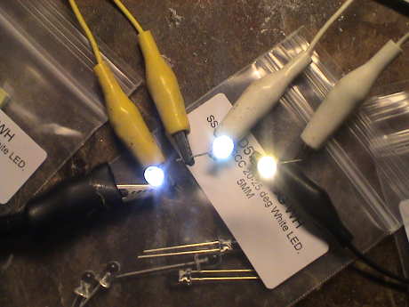 In this photo the current was 1 mA. This is all my camera could
deal with. The color difference is obvious, the warm white one (on
the right) is much more yellow. The color difference didn't change
much by eye at 20 mA but all of them were a lot brighter.
In this photo the current was 1 mA. This is all my camera could
deal with. The color difference is obvious, the warm white one (on
the right) is much more yellow. The color difference didn't change
much by eye at 20 mA but all of them were a lot brighter.
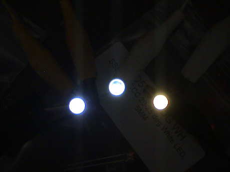 I turned the lights out and took this photo at only 80 µA.
The color hasn't changed much.
I turned the lights out and took this photo at only 80 µA.
The color hasn't changed much.
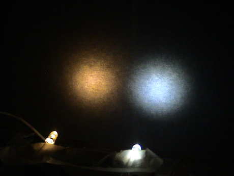 I
pointed the 20+° and the warm white 20° LED at a black
background when both diodes were running at 5 mA. The spot size is
about the same, but the white LED is visually brighter than the
warm white one. This is consistent with the specs where the warm
white one is only supposed to be half as intense. The warm white
one is also too yellow for an electric locomotive headlight but it
would be just right for a kerosene headlight.
I
pointed the 20+° and the warm white 20° LED at a black
background when both diodes were running at 5 mA. The spot size is
about the same, but the white LED is visually brighter than the
warm white one. This is consistent with the specs where the warm
white one is only supposed to be half as intense. The warm white
one is also too yellow for an electric locomotive headlight but it
would be just right for a kerosene headlight.
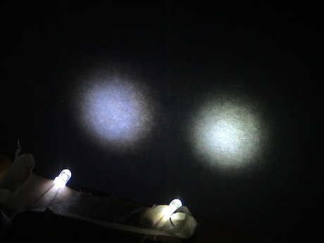 Then I
compared the 30° and 20+° LEDs at 5 mA. In this case the 30
deg one, on the left, is a little fuzzier and not as intense,
again, in agreement with the specs. The cheaper 30° one is also
more blue in color.
Then I
compared the 30° and 20+° LEDs at 5 mA. In this case the 30
deg one, on the left, is a little fuzzier and not as intense,
again, in agreement with the specs. The cheaper 30° one is also
more blue in color.
 These
are two of the 20+° diodes. The left one has a light coating of
Tamiya X-24 Tail Light Yellow paint. It didn't seem to impact the
color as much as it has done on "bluer" diodes in the past. Of
these three diodes, I think that these will work the best.
These
are two of the 20+° diodes. The left one has a light coating of
Tamiya X-24 Tail Light Yellow paint. It didn't seem to impact the
color as much as it has done on "bluer" diodes in the past. Of
these three diodes, I think that these will work the best.
 I still had one
of the older diodes that I had been using for years left over. I
also got these at TheLEDLight.com but at the time (mid 2000) it was
the only version that they had. The older one is obviously a
narrower beam, but it is also not as intense and a little more
blue. It would appear that the diodes have improved over the
years.
I still had one
of the older diodes that I had been using for years left over. I
also got these at TheLEDLight.com but at the time (mid 2000) it was
the only version that they had. The older one is obviously a
narrower beam, but it is also not as intense and a little more
blue. It would appear that the diodes have improved over the
years.
 This photo compares a
warm white 3 mm LED with a similar 5 mm version running at 5 mA.
The 3 mm one has a much broader beam, 60°, and is much less
intense than the 25° beam of the 5 mm unit although both make
the same total light output. The 3 mm version would be better for
area lighting in structures.
This photo compares a
warm white 3 mm LED with a similar 5 mm version running at 5 mA.
The 3 mm one has a much broader beam, 60°, and is much less
intense than the 25° beam of the 5 mm unit although both make
the same total light output. The 3 mm version would be better for
area lighting in structures.
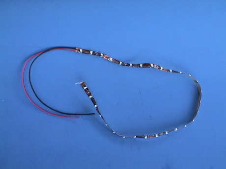 LEDs can also be purchased
in already fabricated strips. This 30 diode white LED strip was
purchased from SuperBrightLEDs.com
for about $20. Strips with colored LEDs are about $7 less.
LEDs can also be purchased
in already fabricated strips. This 30 diode white LED strip was
purchased from SuperBrightLEDs.com
for about $20. Strips with colored LEDs are about $7 less.
The whole strip is built on a flexprint circuit with a peel off adhesive backing.
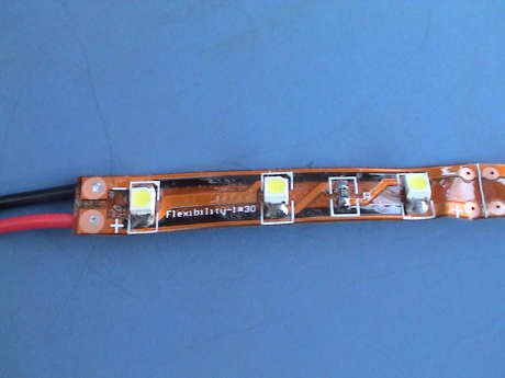 There are 10
individual segments in the strip, each about 2" long, containing 3
diodes and a current limiting resistor in each section. The 10
segments are wired down the strip in parallel so that each section
can, if desired, be cut out with a pair of scissors and wired up
individually. The strip is rated at 9 to 14 VDC. 20 mA per diode is
obtained at 13.5 VDC.
There are 10
individual segments in the strip, each about 2" long, containing 3
diodes and a current limiting resistor in each section. The 10
segments are wired down the strip in parallel so that each section
can, if desired, be cut out with a pair of scissors and wired up
individually. The strip is rated at 9 to 14 VDC. 20 mA per diode is
obtained at 13.5 VDC.
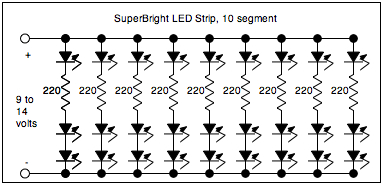 This is a schematic of the
whole 10 segment strip. It's pretty straightforward.
This is a schematic of the
whole 10 segment strip. It's pretty straightforward.
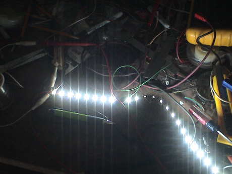 I fired up the
whole strip on my workbench at 12 volts and it's pretty bright, way
brighter than necessary to light an Aristo Heavyweight Coach, for
example. Some of the diodes look much brighter than others. That is
because the strip is twisted and some of the diodes are not facing
the camera.
I fired up the
whole strip on my workbench at 12 volts and it's pretty bright, way
brighter than necessary to light an Aristo Heavyweight Coach, for
example. Some of the diodes look much brighter than others. That is
because the strip is twisted and some of the diodes are not facing
the camera.
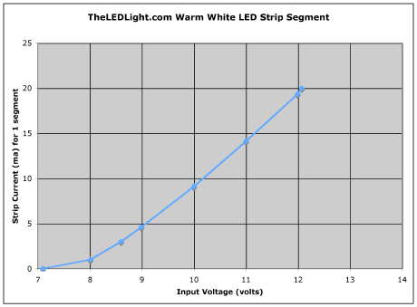
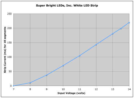 The whole strip makes it's first
visible light at 7 volts, a very dim glow can be seen in each diode
at 4 µA per diode. As the current passes about 4 mA per diode
(40 mA for the strip), the IV curve becomes pretty much linear with
a slope of about 25 ohms. Each diode has a small dynamic impedance,
these add to the 220 ohm resistor on each segment to make about 250
ohms total per segment.
The whole strip makes it's first
visible light at 7 volts, a very dim glow can be seen in each diode
at 4 µA per diode. As the current passes about 4 mA per diode
(40 mA for the strip), the IV curve becomes pretty much linear with
a slope of about 25 ohms. Each diode has a small dynamic impedance,
these add to the 220 ohm resistor on each segment to make about 250
ohms total per segment.
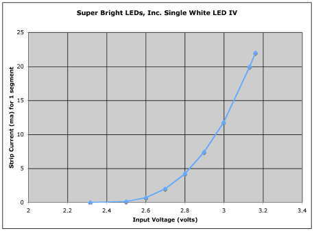 This is a sample IV of a
single diode on that same strip. As is typical of a white LED, it
reaches 20 mA at just above 3 volts.
This is a sample IV of a
single diode on that same strip. As is typical of a white LED, it
reaches 20 mA at just above 3 volts.
To light a standard heavyweight coach on DCC, one would probably use 4 segments spaced down the length of the car with the strips wired in parallel. An additional resistor per strip could then be used to tone the intensity down to the desired value. 2 or 3 mA per segment is about right. A 3.3K or 3.9K resistor in series with each segment produce these currents. This will produce track currents of 8 to 12 mA, a vast improvement over the 300+ mA that the stock car draws. See some more details of an installation in my standard heavyweight tip page.
For a regular track power setup, the strips should be run a single bridge rectifier connected to the track, EACH strip with its own current regulator such as the LM317L described below.
 This is the
IV curve for a similar strip of green LEDs. The physical
arrangement is exactly the same as the white strip. The difference
is the color of the LEDs and the value of the current limiting
resistor which is 240 ohms on this sample.
This is the
IV curve for a similar strip of green LEDs. The physical
arrangement is exactly the same as the white strip. The difference
is the color of the LEDs and the value of the current limiting
resistor which is 240 ohms on this sample.
I am planning on using these strips for lighting Aristo Streamliners which have green filters on the windows anyway.
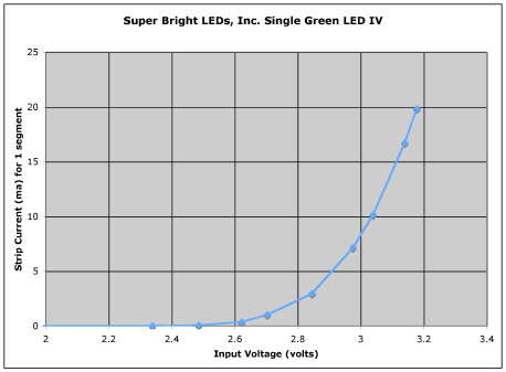 The green diode IV is pretty similar to the
white diode.
The green diode IV is pretty similar to the
white diode.
 SuperBrightLEDs.com
doesn't provide the strips in warm white LEDs as of Sept 2008, but
they say that they will have them in a few months. However, TheLEDLight.com
had virtually the same thing in stock for about the same price per
segment, however, they come in longer 36" strips instead of 20"
strips. This was ok for me as I needed nearly 6' of the things
anyway. The segments are also 2" long and are designed to run at 12
VDC. The current limiting resistor is a little smaller at 150 ohms
so that these strips run at slightly lower voltage.
SuperBrightLEDs.com
doesn't provide the strips in warm white LEDs as of Sept 2008, but
they say that they will have them in a few months. However, TheLEDLight.com
had virtually the same thing in stock for about the same price per
segment, however, they come in longer 36" strips instead of 20"
strips. This was ok for me as I needed nearly 6' of the things
anyway. The segments are also 2" long and are designed to run at 12
VDC. The current limiting resistor is a little smaller at 150 ohms
so that these strips run at slightly lower voltage.
 There is a pronounced
color difference between the "regular" white LEDs (the blue ones)
and the warm white LEDs. By eyeball, the intensity looks to be
about the same.
There is a pronounced
color difference between the "regular" white LEDs (the blue ones)
and the warm white LEDs. By eyeball, the intensity looks to be
about the same.
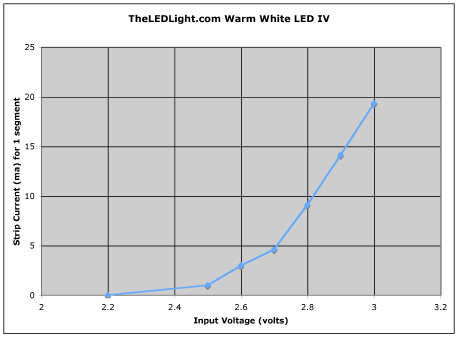
 This is the IV curve
of a single segment of the warm white strip. Due to the lower value
current limiting resistor, the segment reaches it's design current
of 20 mA at just a little over 12 volts.
This is the IV curve
of a single segment of the warm white strip. Due to the lower value
current limiting resistor, the segment reaches it's design current
of 20 mA at just a little over 12 volts.
 The forward voltage of
these diodes is also a little less than the more blue diodes. This
also contributes to the lower operating voltage for these
strips.
The forward voltage of
these diodes is also a little less than the more blue diodes. This
also contributes to the lower operating voltage for these
strips.
[ Top ]
RAM Products produces ready to use white LED headlight circuits, the RAM109 is a typical example. These include the LED and a small voltage regulator board. I bought one of these and was impressed by the intensity of the light, but the owner of the company warned me about using too high an input voltage, above 9 volts. Since I am planning to run it from 22 volts or more, I needed to make some changes. In the process, I believe that a simple modification to RAM's circuit will allow a higher input voltage range AND improve the life of the LED.
 This is the circuit diagram of a RAM109. It is
simply a low current 5 volt regulator that drives the diode. The
problem is that the diode wants to see less than 5 volts, so that
when the regulator comes alive, it over drives the diode, up to 150
mA. I do not know the maximum current capability of the diodes that
RAM uses, but I haven't found any diodes rated past 20 mA. Even the
"ultra bright" LEDs in other colors are rated at 20 mA. A diode
that is run at overcurrent will run brighter, but it won't last as
long.
This is the circuit diagram of a RAM109. It is
simply a low current 5 volt regulator that drives the diode. The
problem is that the diode wants to see less than 5 volts, so that
when the regulator comes alive, it over drives the diode, up to 150
mA. I do not know the maximum current capability of the diodes that
RAM uses, but I haven't found any diodes rated past 20 mA. Even the
"ultra bright" LEDs in other colors are rated at 20 mA. A diode
that is run at overcurrent will run brighter, but it won't last as
long.
 This is the response of the RAM109 regulator with a DC
power input. Note that the peak current is 150 mA which might be
7.5 times the diode rating. This cannot be good for the diode.
This is the response of the RAM109 regulator with a DC
power input. Note that the peak current is 150 mA which might be
7.5 times the diode rating. This cannot be good for the diode.
 I purchased a generic
white LED at Fry's. I don't know who manufactured this diode, but
it is rated at 20 mA, the only current rating that I have seen for
white LEDs. I was able to drive it up to 117 mA and it didn't burn
out and it was REALLY bright. This diode makes its first light at
about 1 mA and by 3 mA it is too bright to look at directly. Its
appearance, turn on characteristics and brightness are roughly the
same as the diode that came with the RAM109. This IV curve is
log-normal up to about 20 mA. After that, it saturates, the voltage
goes up but the current does not go up fast enough. This indicates
that the diode is screaming in pain. The power dissipation and
therefore the temperature of the LED is increasing rapidly.
I purchased a generic
white LED at Fry's. I don't know who manufactured this diode, but
it is rated at 20 mA, the only current rating that I have seen for
white LEDs. I was able to drive it up to 117 mA and it didn't burn
out and it was REALLY bright. This diode makes its first light at
about 1 mA and by 3 mA it is too bright to look at directly. Its
appearance, turn on characteristics and brightness are roughly the
same as the diode that came with the RAM109. This IV curve is
log-normal up to about 20 mA. After that, it saturates, the voltage
goes up but the current does not go up fast enough. This indicates
that the diode is screaming in pain. The power dissipation and
therefore the temperature of the LED is increasing rapidly.
 There
are three ways to deal with this problem, however, all of them are
fundamentally the same. An LED is primarily a current driven device
so it wants to get its power from a current source. If the source
voltage is high enough, a simple series resistor simulates an
acceptable current source. If the LED is to run from a fairly high
fairly constant voltage, such as the function output of a DCC
decoder (about 20 volts), or an onboard battery (12-18 volts), or a
Bachmann Shay or Climax flicker board (about 9 volts), or a
Soundtraxx Sierra lighting output (about 6.8 volts) then the value
of a suitable resistor can be read from this curve and the diode
current will be acceptably close to 20 mA.
There
are three ways to deal with this problem, however, all of them are
fundamentally the same. An LED is primarily a current driven device
so it wants to get its power from a current source. If the source
voltage is high enough, a simple series resistor simulates an
acceptable current source. If the LED is to run from a fairly high
fairly constant voltage, such as the function output of a DCC
decoder (about 20 volts), or an onboard battery (12-18 volts), or a
Bachmann Shay or Climax flicker board (about 9 volts), or a
Soundtraxx Sierra lighting output (about 6.8 volts) then the value
of a suitable resistor can be read from this curve and the diode
current will be acceptably close to 20 mA.
 If the
diode is to be run from a variable voltage source, such as track
power, then a regulator of some kind will do a better job of
controlling the intensity of the LED. This is the circuit of a
regulator for a white LED. The only significant difference between
this circuit and the RAM109 is the addition of a resistor to take
up the voltage difference between the output of the regulator and
the needs of the diode. The current in the diode is set by the
value of this resistor. The diode current will be
I=(5-Vf)/R where Vf is usually about 3.4
volts but it depends on the actual diode used. The 75 ohm resistor
sets the current at a little more than 20 mA. An 82 ohm resistor
will set the diode current at just below 20 mA. Users of the RAM
circuit should probably consider adding a resistor in series with
either wire to the LED.
If the
diode is to be run from a variable voltage source, such as track
power, then a regulator of some kind will do a better job of
controlling the intensity of the LED. This is the circuit of a
regulator for a white LED. The only significant difference between
this circuit and the RAM109 is the addition of a resistor to take
up the voltage difference between the output of the regulator and
the needs of the diode. The current in the diode is set by the
value of this resistor. The diode current will be
I=(5-Vf)/R where Vf is usually about 3.4
volts but it depends on the actual diode used. The 75 ohm resistor
sets the current at a little more than 20 mA. An 82 ohm resistor
will set the diode current at just below 20 mA. Users of the RAM
circuit should probably consider adding a resistor in series with
either wire to the LED.
 The 75 to
82 ohm resistor makes this circuit approximate a current source as
the source voltage is well regulated and the diode current will be
well controlled at a current level of about 20 mA. The input
current to the circuit will be 5 mA or so higher than the LED
current because the regulator itself draws a little current. Note
that when the input voltage is high enough, the diode current is
nearly constant and won't increase to an unsafe level. If you use a
regular 7805 regulator in a TO-220 package (metal tab on the
package) you can drive several diodes in parallel but each diode
needs its own resistor. The regulator may require an additional
heat sink. The TO-92 (plastic case) 78L05 regulator can handle only
one diode and just barely at that.
The 75 to
82 ohm resistor makes this circuit approximate a current source as
the source voltage is well regulated and the diode current will be
well controlled at a current level of about 20 mA. The input
current to the circuit will be 5 mA or so higher than the LED
current because the regulator itself draws a little current. Note
that when the input voltage is high enough, the diode current is
nearly constant and won't increase to an unsafe level. If you use a
regular 7805 regulator in a TO-220 package (metal tab on the
package) you can drive several diodes in parallel but each diode
needs its own resistor. The regulator may require an additional
heat sink. The TO-92 (plastic case) 78L05 regulator can handle only
one diode and just barely at that.
 If a
constant current source is what is really desired, then an
adjustable voltage regulator circuit, the LM317, can be wired as a
current regulator. In this case, the current is set by the 62 ohm
resistor. The current will be I=1.25/R. You can also use a LM317L
(or the equivalent NTE1900) in a TO-92 package to drive a single
diode (or more than one if they are wired in series). The LM317L
will run a little hot, but it'll work up to 30 volts input.
If a
constant current source is what is really desired, then an
adjustable voltage regulator circuit, the LM317, can be wired as a
current regulator. In this case, the current is set by the 62 ohm
resistor. The current will be I=1.25/R. You can also use a LM317L
(or the equivalent NTE1900) in a TO-92 package to drive a single
diode (or more than one if they are wired in series). The LM317L
will run a little hot, but it'll work up to 30 volts input.
If you do run diodes in series, it'll take another 3.4 volts or so of input voltage per extra diode to make the circuit work. This would be an appropriate solution in the case of onboard battery power, DCC or constant track power as there would always be enough voltage to operate the circuit. This configuration allows several diodes (of different types/colors if desired) to share the same 20 mA so that it also minimizes the total current draw.
Don't try to parallel diodes from a current regulator, the diodes will not share current properly unless you add a balancing resistor in series with each diode. In that case, you might as well use the 7805 constant voltage regulator.
 The
LM317 current regulator has just a little less overhead voltage
than the circuit with the 7805 in it. It also doesn't care what the
LED voltage is, it'll drive 20 mA into any single diode or a stack
of various diodes. When running a single diode, there is not a lot
of difference in performance between the two circuits, use
whichever one you have the parts for.
The
LM317 current regulator has just a little less overhead voltage
than the circuit with the 7805 in it. It also doesn't care what the
LED voltage is, it'll drive 20 mA into any single diode or a stack
of various diodes. When running a single diode, there is not a lot
of difference in performance between the two circuits, use
whichever one you have the parts for.
 If the circuits are to be run from track power or
DCC then a circuit called a full wave bridge rectifier needs to be
used to convert the track power to a constant polarity so that the
lighting will be on all the time that track power is present. This
circuit outputs a fixed polarity DC voltage that the any of the
three circuits above (resistor current limiter, voltage regulator
or current regulator) can use. The voltage drop of the rectifier
increases the input voltage that it takes to run the circuit by
about 1.5 volts.
If the circuits are to be run from track power or
DCC then a circuit called a full wave bridge rectifier needs to be
used to convert the track power to a constant polarity so that the
lighting will be on all the time that track power is present. This
circuit outputs a fixed polarity DC voltage that the any of the
three circuits above (resistor current limiter, voltage regulator
or current regulator) can use. The voltage drop of the rectifier
increases the input voltage that it takes to run the circuit by
about 1.5 volts.
The capacitor is only of value if you are using Aristo PWC or another form of pulsed track power. It charges up on the peaks and dribbles out energy over time to fill in the empty spaces between pulses. Also, some of the regulators can get unstable unless they have an filter capacitor of some kind.
 If instead you
want directional lighting, then use this half wave rectifier
circuit. It will allow the LED to come on in one direction only. By
using any of the regulator or current limiter approaches from PWC
track power, the LED will come on at 100% full intensity at the
first application of track power, well before any locomotive will
start to move. If you do use PWC, then the resistor current limiter
approach is highly effective and it the least complicated approach,
just use this circuit with an 820 ohm resistor in series with the
diode.
If instead you
want directional lighting, then use this half wave rectifier
circuit. It will allow the LED to come on in one direction only. By
using any of the regulator or current limiter approaches from PWC
track power, the LED will come on at 100% full intensity at the
first application of track power, well before any locomotive will
start to move. If you do use PWC, then the resistor current limiter
approach is highly effective and it the least complicated approach,
just use this circuit with an 820 ohm resistor in series with the
diode.
If you use linear track power, then the capacitor is not necessary. It provides an advantage only when there is pulsed power on the track. However, in some instances, the active regulators can get unstable without a bypass capacitor. Any value from 0.1µ up can be substituted to stabilize the regulator.
If you simply want a directional headlight and are using regular track power and are just using a resistor to limit the diode current, then you may not need a rectifier at all. An LED is a diode and it will pass current in one direction only without any help from other circuits, within limits.
 The LED generates light when current passes through it in
the "forward" direction. This curve shows the forward IV
characteristics of four sample diodes. The yellow diode is an
Aristo yellow LED that came out of a Center Cab switcher. The red
and green LEDs are just two unknown heritage diodes that I got in a
grab bag of diodes at an electronics swap meet. The only thing that
I know about these is that they are red and green and they do make
light. The white LED is a 5600 mcd 5 mm diode from The LED Light.
The important thing to note is that the red, green and yellow
diodes are all Gallium Arsenide devices and all have about the same
forward voltage drop. All their red, green and yellow cousins will
be about the same. The white LED is an Indium Gallium Nitride
device and has a considerably higher forward voltage drop. All
other white LEDs of the same technology will be about the same.
The LED generates light when current passes through it in
the "forward" direction. This curve shows the forward IV
characteristics of four sample diodes. The yellow diode is an
Aristo yellow LED that came out of a Center Cab switcher. The red
and green LEDs are just two unknown heritage diodes that I got in a
grab bag of diodes at an electronics swap meet. The only thing that
I know about these is that they are red and green and they do make
light. The white LED is a 5600 mcd 5 mm diode from The LED Light.
The important thing to note is that the red, green and yellow
diodes are all Gallium Arsenide devices and all have about the same
forward voltage drop. All their red, green and yellow cousins will
be about the same. The white LED is an Indium Gallium Nitride
device and has a considerably higher forward voltage drop. All
other white LEDs of the same technology will be about the same.
 When operating as a reversing headlight directly from
track power, the LED on the "rearward" end of the loco will be off.
The diode is said to be reversed biased and no current should flow.
However all diodes have an avalanche or breakdown voltage. This is
the highest voltage that the diode can stand before it starts to
conduct in the reverse direction. Reverse conduction is very hard
on any diode not designed for it. Whatever current that does flow
will do so with high voltage impressed across the diode and the
dissipation will be very high and could result in rapid thermal
destruction of the diode.
When operating as a reversing headlight directly from
track power, the LED on the "rearward" end of the loco will be off.
The diode is said to be reversed biased and no current should flow.
However all diodes have an avalanche or breakdown voltage. This is
the highest voltage that the diode can stand before it starts to
conduct in the reverse direction. Reverse conduction is very hard
on any diode not designed for it. Whatever current that does flow
will do so with high voltage impressed across the diode and the
dissipation will be very high and could result in rapid thermal
destruction of the diode.
For example, if this particular red diode were used in a reversing headlight application, the first time that it saw more than 20 volts, it would conduct large currents in the reverse direction and probably blow up in a short second. Discerning observers may note that the reverse IV of the red diode has a slight negative resistance component. This really happens on this particular diode, the Vr does go down a little with increasing Ir.
Most of the white LEDs are rated for a Vr (reverse voltage) of just 5 volts. This is not high enough to cause the diode to block reverse currents and if it really is that low, the LED will need another rectifier diode in series with it to block reverse currents. I tested one white LED and found that at 20 volts and below, it blocked current adequately well and that the leakage at 30 volts would result in only 1.5 mW of dissipation, an acceptable value. All white LEDs may not be the same. A manufacturer does not rate the reverse voltage at such a low value without a reason, some of the diodes may indeed have very high leakage at lower reverse voltage and might need an external blocking diode. Note that just adding two 20 volt diodes in series does not make a 40 volt diode. Their leakages may be significantly different and the low leakage diode will see most of the voltage.
If you need to locate a source of regulators or need data sheets to determine the pinouts you can try these links.
| Regulator Type | National Semiconductor Data Sheets |
NTE Electronics Data Sheets |
Radio Shack Part Numbers |
|---|---|---|---|
| Adjustable Regulator TO-220 case |
LM317 | NTE956 | 276-1778 |
| Adjustable Regulator TO-92 case |
LM317L | NTE1900 | N/A |
| 5 Volt Fixed Regulator TO-220 case |
7805 | NTE960 | 276-1770 |
| 5 Volt Fixed Regulator TO-92 case |
78L05 | NTE977 | N/A |
[ Top ]
Due to some problems I had during LED installation in an Aristo RDC after I installed a DCC decoder, I ended up running the headlights with a pulsed waveform. I would have preferred to use DC, but circumstances conspired against me. The RDC, and all recent Aristo locos, use a Pulse Width Modulator to provide quasi-constant intensity lighting. The PWM generates pulses that vary in width and peak voltage. As the track voltage, and therefore the PWM pulse voltage goes up, the width of the pulses goes down to keep the total energy available more or less constant. This PWM circuit has a PRF (pulse repetition frequency) of about 6 kHz. At high track voltages, about 22 volts, the DF (duty factor or pulse on to off ratio) is about 10%. The headlights get this 10% DF pulse and the LED intensity is about 10% of what one might expect because the LED is on only 10% of the time. The incandescent stock headlight can integrate, or average, these pulses, an LED cannot.
I ended up just fiddling with the LED's current limiting resistor to allow the peak current to be much higher than the 20 mA that I would use with DC to get adequate intensity. I did this by eye, I kept increasing the peak current until the LED didn't seem to get brighter then I backed off a little. This worked out to 150 mA peak current 10% of the time, or 15 mA of average current. The LED wasn't making as much light as it would at 15 mA DC, but it was adequate.
Later, I decided to actually make some measurements of the intensity of the LED's output under DC and pulsed conditions. I used a Pentax Spotmeter V to evaluate the light output. This meter measured in EV, or exposure value. This is a relative indication of light intensity, an increase of 1 EV doubles the light intensity. The Spotmeter is marked in 1/3 EV steps from EV 1 to EV 19. The dimmest measurements that I made were about EV 8 with background lighting of EV 3 which means that the background light was only about 3% of the lowest measured LED light.
The DC measurements were made with a bench power supply and a current limiting resistor of 400 ohms. I used a true RMS current meter to measure and set the DC current. I did the pulsed measurements two ways. I used a trackside TE receiver for the pulses. These vary in width at a 24 kHz PRF to produce a duty factor of 0% (no pulses) to 100% when the output is DC at about 20 volts. I also set the DF to as close to 10% as I could (to approximate the duty factor of the Aristo PWM). This produced a pulse width of 4 uS, less than the 15 uS of the Aristo PWM but short enough. Both are much less than the thermal time constant of the LED die (about 50 uS) so that the temperature of the LED itself will be integrated and the LED won't reach the high temperatures that it would achieve with a similar DC current. Also, with the 4 uS pulse and 10% duty factor, I varied the current limiting resistance to achieve a varying peak, and therefore a varying RMS current.
 The blue curve is the response
to DC current. The curve is nearly straight (log-normal) until
about 20 mA and then it begins to taper off. After 20 mA, less
incremental increases in light are produced for increasing current.
This is why most of the diodes are rated at or near 20 mA. Even
though they will take more, they get less efficient and MUCH
hotter.
The blue curve is the response
to DC current. The curve is nearly straight (log-normal) until
about 20 mA and then it begins to taper off. After 20 mA, less
incremental increases in light are produced for increasing current.
This is why most of the diodes are rated at or near 20 mA. Even
though they will take more, they get less efficient and MUCH
hotter.
Under pulsed conditions, the LED isn't as efficient as a function of RMS current. RMS (root mean square) is a measure of the energy in any given waveform. In the case of DC current, the RMS and DC values are the same. In a rectangular pulse case, the RMS value is factored by the duty factor. For more complex waveforms, an integration must be performed to determine the RMS value of any given waveform. From 1 mA to about 30 mA RMS, the amount of light produced by the pulsed LED is down by as much as 2 to 3 EV (1/4 to 1/8) for the same RMS current. The LED is clearly not as efficient. When the duty factor of the variable pulse width curve (red) gets really high, the efficiency starts to come back up because the waveform is approaching DC. At 30 mA, the highest current on the red curve, the TE is producing DC and the red curve touches the blue curve. Below 2 mA or so, the peak current is less than 20 mA and the LED is efficient. As the peak current increases past 20 mA, the LED efficiency starts to fall off.
The yellow curve keeps the duty factor constant at about 10% to roughly approximate the duty factor of the Aristo PWM board with high track voltage. In this case at 1 mA RMS or less, the result is about the same. Between 1 mA RMS and 10 mA RMS, the yellow and red curve track. However, above 10 mA RMS, the yellow curve saturates as the only way to get more RMS current is to use higher peak currents.
 This curve shows what happens
to the LED intensity as a function of peak current at a constant
duty factor of 10%. Past about 20 mA peak current, not much more
light is generated. An increase of 10x in current produces only 2x
more light. The LED generates only 1/8 as much light as it would
with DC. This is not the best way to use an LED, but when it's what
you have, you take it.
This curve shows what happens
to the LED intensity as a function of peak current at a constant
duty factor of 10%. Past about 20 mA peak current, not much more
light is generated. An increase of 10x in current produces only 2x
more light. The LED generates only 1/8 as much light as it would
with DC. This is not the best way to use an LED, but when it's what
you have, you take it.
[ Top ]
I've been scanning the net for suppliers and manufacturers of white LED's and so far I've found several. This list will grow as I find more.
 Since this page was
originally written, the manufacturing costs of white LEDs has come
way down. When purchased as individual pieces, they are still
pretty expensive, but when purchased as parts of a lighting
assembly, they are cheap. One of the lowest costs sources that I
have found are Christmas light strings. Costco has this set of 100
warm white LEDs for $13.99. That is $0.14 per LED. I bought a set
for evaluation and I find that they are good parts. They are 4x
brighter at the same current as the parts that I got at the
theLEDLight.com which cost over $1 each. These are 3 mm LEDs set in
a plastic base like conventional mini lights. The LEDs themselves
are easy to removed from the string. Just pull all the diodes and
chuck the rest. These parts are also more white than the older warm
white LEDs but less blue than the original "white" LEDs. The extra
brightness MAY come from a tighter beamwidth or from better diodes,
I don't know which. These still have a broader beam than the 5 mm
packages so that they would do better for general lighting than for
headlights. However, they are cheap enough so that one string could
last quite a while, at least until next Christmas when you can
probably the same set for less.
Since this page was
originally written, the manufacturing costs of white LEDs has come
way down. When purchased as individual pieces, they are still
pretty expensive, but when purchased as parts of a lighting
assembly, they are cheap. One of the lowest costs sources that I
have found are Christmas light strings. Costco has this set of 100
warm white LEDs for $13.99. That is $0.14 per LED. I bought a set
for evaluation and I find that they are good parts. They are 4x
brighter at the same current as the parts that I got at the
theLEDLight.com which cost over $1 each. These are 3 mm LEDs set in
a plastic base like conventional mini lights. The LEDs themselves
are easy to removed from the string. Just pull all the diodes and
chuck the rest. These parts are also more white than the older warm
white LEDs but less blue than the original "white" LEDs. The extra
brightness MAY come from a tighter beamwidth or from better diodes,
I don't know which. These still have a broader beam than the 5 mm
packages so that they would do better for general lighting than for
headlights. However, they are cheap enough so that one string could
last quite a while, at least until next Christmas when you can
probably the same set for less.
[ Top ]
The typical white LED has a kind of a blue cast, an inappropriate color for nearly any kind of locomotive headlight. This can be modified to some extent at a small loss in intensity. Recently a post was placed on an internet bulletin board concerning painting the LEDs to change their color. I couldn't find the post again, but I did remember that the author recommended using Testor's Turn Signal Amber to paint the diode lens. I decided to try it out with that paint and a couple of others.
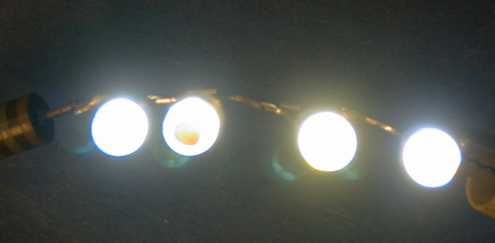 These four diodes are wired in series and are
running exactly the same current. The one on the left is unpainted,
the next one is painted with Testor's Insignia Yellow, the next
with Tamiya X-24 Clear Yellow and the rightmost one is painted with
Testor's Turn Signal Amber. This photo was taken at much less than
20 mA because at full intensity, the LEDs drove my camera nuts. The
unpainted one is characteristically blue. The Insignia Yellow is
partially opaque so that it did more to block the light than
anything else. The Tamiya Clear Yellow seemed did remove most of
the blue cast and seemed to do a better job than the Testor's Turn
Signal Amber. The Tamiya paint also flowed better. Both the Tamiya
Clear Yellow and Testor's Turn Signal Amber are translucent paints
and do impact the intensity a little. The Testor's paint is an oil
base, the Tamiya is an acrylic.
These four diodes are wired in series and are
running exactly the same current. The one on the left is unpainted,
the next one is painted with Testor's Insignia Yellow, the next
with Tamiya X-24 Clear Yellow and the rightmost one is painted with
Testor's Turn Signal Amber. This photo was taken at much less than
20 mA because at full intensity, the LEDs drove my camera nuts. The
unpainted one is characteristically blue. The Insignia Yellow is
partially opaque so that it did more to block the light than
anything else. The Tamiya Clear Yellow seemed did remove most of
the blue cast and seemed to do a better job than the Testor's Turn
Signal Amber. The Tamiya paint also flowed better. Both the Tamiya
Clear Yellow and Testor's Turn Signal Amber are translucent paints
and do impact the intensity a little. The Testor's paint is an oil
base, the Tamiya is an acrylic.
The beam cast by the Testor's treated diode onto a white sheet of paper shows a loss of intensity as compared to the Tamiya painted diode. The Tamiya treated diode casts a yellowish beam onto white paper and has considerably better uniformity than the Testor's treated diode. The intensity of the Tamiya diode seems to be about the same as the untreated diode. The diode painted with Insignia Yellow produced a significantly dimmed and nonuniform beam without much color improvement.
Don't overdo the paint. All it takes is a very thin film to cut the hard blue color. Too much paint will result in either a yellow or green beam. Either dry brush the lens or airbrush the lens.
All you need to do is dab a little paint on the lens. One coat seems adequate to shift the color back toward the yellow more like a real headlight.
This center cab switcher has had the right headlight painted with the Tamiya Clear Yellow. The difference in color and intensity is not huge, but the blue cast is reduced. The visual effect by eye is larger than the camera shows, probably due to saturation of the camera's imager by the intense LEDs.
In operation in darkness, the painted LEDs cast a whiter looking beam. With the Tamiya paint, the intensity is not significantly reduced, it still lights up objects 20 feet ahead. Looking directly at the beam reveals a very slight greenish cast. This greenish color does not show in the objects illuminated by the beam.
It is possible to paint LEDs of other colors too. I put an 8 degree beamwidth, 8000 mcd red LED in the rear of an Aristo Doodlebug and used it as a FRED. The beam was so tight that the LED was only poorly visible in daylight unless you were looking straight down its beam. In that case, it was much too bright. I painted that one with Tamiya X-27 Clear Red. This did two things. First, it diffused the beam from the LED and caused the LED to be clearly visible from any angle in daylight without materially reducing the intensity in the beam. Second, since this LED has a water clear lens, it made the LED look red even when it was off. This simulated the red lens of a FRED better.
[ Top ]
Where I have to get into an engine for any reason, I am going to change out the headlight. These are links to the circuit implementations that have been used to install a White LED headlight.
| Engine | LED Type | Circuit Type | Link | Author |
|---|---|---|---|---|
| Bachmann Big Hauler | 5 mm, 20 mA | Resistor Current Limiter | Big Hauler Tips | George Schreyer |
| Aristo C-16 | 5 mm, 20 mA | Resistor Current Limiter | C-16 Tips | George Schreyer |
| Aristo FA-1 | 5 mm, 20 mA | Resistor Current Limiter from Soundtraxx Sierra | FA Tips | George Schreyer |
| Aristo Center Cab | 5 mm, 20 mA | Resistor Current Limiter | Aristo Center Cab Tips | George Schreyer |
| Aristo L'il Critter and USA GP-9 | 5 mm, 20 mA | Resistor Current Limiter | Super bright white LED's | Jon Foster |
| Aristo SD45 | 5 mm, 20 mA | Resistor Current Limiter Headlights Sierra Driven Ditch Lights |
SD45 Tips | George Schreyer |
| USA Trains GP9 | 5 mm, 20 mA | Resistor Current Limiter Headlights DCC Decoder Driven Ditch Lights |
GP9 Tips | George Schreyer |
| Aristo RDC | 5 mm, 20 mA | Pulsed Resistor Current Limiter | RDC Tips | George Schreyer |
| Bachmann Heisler | 5 mm, 20 mA | Resistor Current Limiter | Heisler Tips | George Schreyer |
This page has been accessed times since 11 June 00.
© 2000-2009 George Schreyer
Created June 11, 2000
Last Updated October 21, 2009