 3 Aug 08 21 May 09
[ Home ] [ Up ] [ Previous Page ] [ Next Page ]
3 Aug 08 21 May 09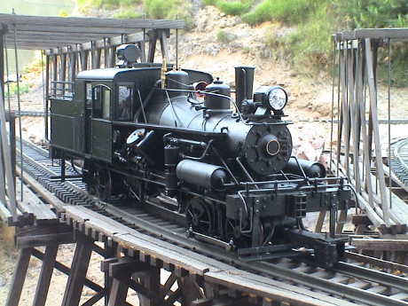 The
Heisler was the third major type of geared steam locomotive
after the Shay and Climax. There were actually two others, the
Dunkirk and the Davenport, but these two never attained much
popularity. Heislers were built from 1891 through 1941 and were
claimed the be the fastest of the geared steamers.
The
Heisler was the third major type of geared steam locomotive
after the Shay and Climax. There were actually two others, the
Dunkirk and the Davenport, but these two never attained much
popularity. Heislers were built from 1891 through 1941 and were
claimed the be the fastest of the geared steamers.
The locomotives were driven from a 90° V-twin configuration engine which drove centered drive shafts under the loco. The shaft drove the outboard axle on the truck, the other axle was driven through siderods.
I believe that Bachmann produced just one production run of Heislers and there aren't many around anymore. A Bachmann rep at the Big Train Show in 2008 indicated that there were no plans in place to make more of them.
After a couple of weeks of on and off work on the loco, it now runs very well. As is typical of most large scale stuff, the loco was not quite right out of the box. It made some annoying noises, had issues with DCC and Aristo PWC, the headlights were wimpy, it was too tall, and it needed different couplers. All this has been changed to my satisfaction and it has been accepted for service on the GIRR Mountain Division.
The Bachmann model of the Heisler is a very well detailed 1:20.3 model of a 36 ton Heisler, circa 1920. I got a painted but unlettered model which represents a coal burner. This is a finely detailed model with good running characteristics (after some electrical changes) although it does make some noise.
The loco has reversing headlights, but they are wimpy yellow LEDs. This is going to be changed at some point. I'll probably have to move the roof mounted rear headlight as I don't have the vertical clearance for it on the GIRR Mountain Division.
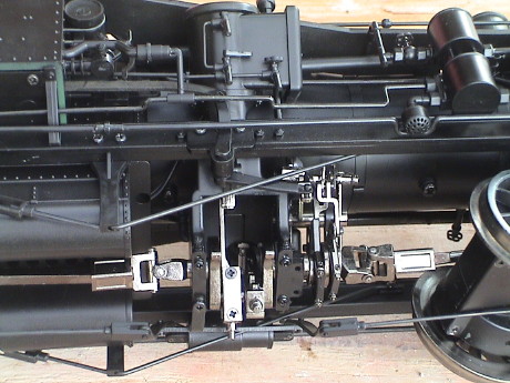 The V-twin engine is just loaded with moving parts.
Unlike the Climax, the "engine" does not allow a torque transfer.
It is interesting that the front truck drives the valve gear and
the rear truck drives the engine itself so that sticklers for
detail will fret that the valve gear is never in sync with the
engine.
The V-twin engine is just loaded with moving parts.
Unlike the Climax, the "engine" does not allow a torque transfer.
It is interesting that the front truck drives the valve gear and
the rear truck drives the engine itself so that sticklers for
detail will fret that the valve gear is never in sync with the
engine.
The driveline parts are all metal with functional universal and slip joints.
The Heisler represents only a 36 ton locomotive, but it is 1:20.3 scale so it is physically pretty large. The cab and tender are on the wide side but it did just barely fit the narrow spots on the GIRR Mountain division. The end steps barely clear Aristo turnout motors.
 The
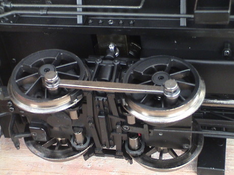
trucks are mostly die cast metal parts. The brake rods are
simulated. The loco body is supported on the trucks via rollers.
All the axles run in ball bearings. Power pickup is via roller
contacts riding against the backs of the wheels.
The
trucks are mostly die cast metal parts. The brake rods are
simulated. The loco body is supported on the trucks via rollers.
All the axles run in ball bearings. Power pickup is via roller
contacts riding against the backs of the wheels.
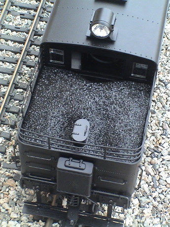 My loco is
a coal burner although it came with an oil stack installed. The
coal load can be removed. The instructions indicate that it can
simply be lifted out. However, there is a screw under the water
hatch which must be removed first.
My loco is
a coal burner although it came with an oil stack installed. The
coal load can be removed. The instructions indicate that it can
simply be lifted out. However, there is a screw under the water
hatch which must be removed first.
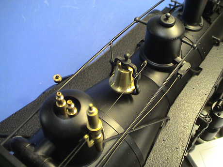 The top of the boiler
has a steam dome with two brass pop off valves and a plastic
whistle. The bell is brass with two steel ringer wires leading back
to the cab. The sander rod is also a steel wire and it moves
somewhat.
The top of the boiler
has a steam dome with two brass pop off valves and a plastic
whistle. The bell is brass with two steel ringer wires leading back
to the cab. The sander rod is also a steel wire and it moves
somewhat.
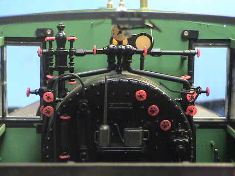 The backhead detail
is very good with many pipes, gauges and valves. There are a couple
of oil cans on the hot shelf.
The backhead detail
is very good with many pipes, gauges and valves. There are a couple
of oil cans on the hot shelf.
 The firebox door
opens to reveal a flickering firebox simulation.
The firebox door
opens to reveal a flickering firebox simulation.
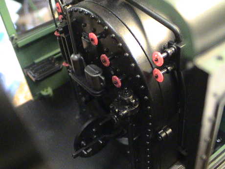
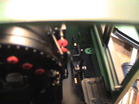 The reversing lever
actually operates and changes the operation of the valve gear. The
lever is difficult to get to without removing the cab roof. It must
be lifted to be pushed forward or backward.
The reversing lever
actually operates and changes the operation of the valve gear. The
lever is difficult to get to without removing the cab roof. It must
be lifted to be pushed forward or backward.
There is a slot in the cab floor under the reversing lever to allow the lever to be pushed upward with a small tool. Then the position of the lever can be changed by manually moving the linkage to the valve gear. I whittled a toothpick to fit in the slot.
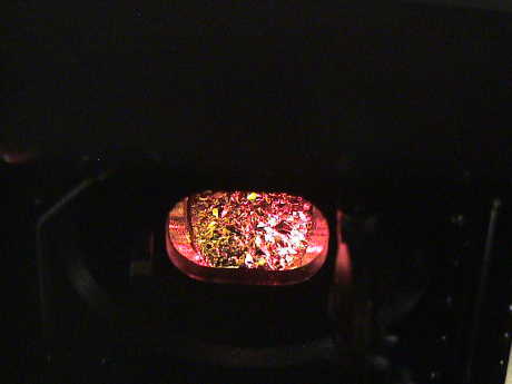 The firebox has the typical
Bachmann red/yellow flicker, but it does have a nice effect.
The firebox has the typical
Bachmann red/yellow flicker, but it does have a nice effect.
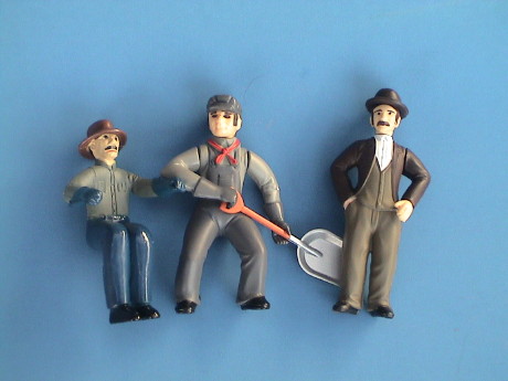 The locomotive comes with a seated engineer, a fireman
and another figure who look like he shouldn't be in a locomotive
cab.
The locomotive comes with a seated engineer, a fireman
and another figure who look like he shouldn't be in a locomotive
cab.
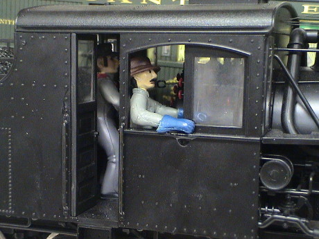 The
engineer and fireman fit into the cab, but the engineer's legs need
to be cut off or he can't sit down due to interference with the
reversing lever. He is glued on only at his arm in the window so
that the arm is held tightly against the side of the loco. The glue
drip has been fixed.
The
engineer and fireman fit into the cab, but the engineer's legs need
to be cut off or he can't sit down due to interference with the
reversing lever. He is glued on only at his arm in the window so
that the arm is held tightly against the side of the loco. The glue
drip has been fixed.
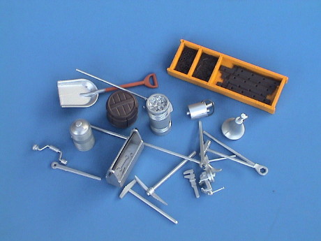 Like
the Shay, a pretty complete tool set comes with the loco.
Like
the Shay, a pretty complete tool set comes with the loco.
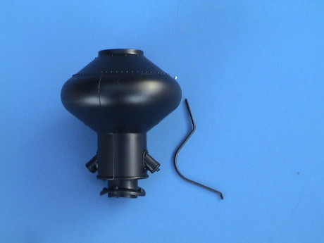 Perhaps due to packaging issues, a balloon stack is
packed separately.
Perhaps due to packaging issues, a balloon stack is
packed separately.
Aside from some clattering noise, the engine runs very smoothly. However, mine didn't run at all when it was placed on the track. There is a switch behind the firebox door to reverse the polarity of the motors. This switch has a center off position which is where mine was set. To match the large scale standard, the switch should be pushed to the fireman's side. The switch controls the motors only. When standing with the motors off, the lights and smoke will still run.
 Power pickup is on all 8 wheels and the locomotive
had no power pickup difficulty at all on my less than perfectly
clean track at the GIRR. The power pickups themselves are the roller type
contact that I first saw on the Bachmann railtruck. This kind of
contact seems to work quite well, has low drag and makes no
perceptible noise. However, they are probably sensitive to proper
lubrication so pay attention to them.
Power pickup is on all 8 wheels and the locomotive
had no power pickup difficulty at all on my less than perfectly
clean track at the GIRR. The power pickups themselves are the roller type
contact that I first saw on the Bachmann railtruck. This kind of
contact seems to work quite well, has low drag and makes no
perceptible noise. However, they are probably sensitive to proper
lubrication so pay attention to them.
The top speed of the loco is definitely faster than the Climax and Shay, but slower than other typical large scale locos. This follows the prototype where the Heisler is fast for a geared steam loco, but not nearly as fast as most rod locos.
The truck flexibility is restricted to relatively small side to side and front to back rocking movements so that the Heisler is somewhat sensitive to poorly leveled track. It did have some systematic derailment problems on particular stretches of track at the GIRR Mountain Division so these needed to be fixed before it would run on them. After the track was fixed, the Heisler ran fine.
Because of all the detail hanging off the engine, this is not one that should be touched by children. There is lots of stuff, especially underneath, that are fairly fragile and could easily be broken off or damaged by less than very cautious handling.
The loco is moderately heavy and must be lifted carefully. There appear to be two fairly safe ways of picking up the loco. One is by the end beams, the other is by the ashpans.
You can fit at least two fingers under each end beam by working around the sanding lines and the coupler. This method makes it a little more difficult to stabilize the loco so it is best to let it lean against your belly while you are carrying it.
Heislers have two cylindrical ashpans to allow passage of the rear drive line. Reach under the fire box and feel for the cylinders. Use two or three fingers on each side and then stabilize the loco with your palms along the cab sides.
In either case, place your fingers in these locations and then feel around a little to make sure that your aren't putting pressure on detail parts.
 The drive gearing itself produces a light whine
which is completely acceptable. However somewhere in the engine and
valve gear assembly, there is something that clatters.
The drive gearing itself produces a light whine
which is completely acceptable. However somewhere in the engine and
valve gear assembly, there is something that clatters.
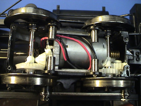
There is a motor in each truck that has a worm on one shaft. The worm drives a couple of intermediate reduction gears which eventually drives the outboard axle. The inboard axle is driven via the siderods. A bevel gear on the inboard axle drives another gear train that backdrives the drive shaft to operate the "engine." The front truck drives the valve gear portion and the rear truck drives the crankshaft of the engine. Unlike the prototype, the driveline is geared to the inboard axle of each truck.
All this motion going on underneath produces some clattering noise.
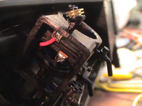
I found 4 loose wires in the tender, taped off and not connected to anything. There are two pairs of one red and one black wire each. They do not show in the wiring diagram. I also noticed that just where they vanished into the wiring tunnel, the wires were painted black. There are also four painted wires snaking across the bottom of the boiler, one pair goes in the direction of each cylinder. I figured that these must be chuff switch wires. By testing continuity on one pair, I found that they are indeed chuff switch wires which means that there are chuff switches inside the cylinders.
 When the cylinder head
is popped off, sure enough the switches are there. The fireman's
side is easier to work with.
When the cylinder head
is popped off, sure enough the switches are there. The fireman's
side is easier to work with.
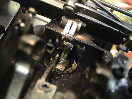
 Removing the slide
valve cover shows the soldered connections to the switches. They
look like they might slide out, but this one didn't budge with a
fair amount of force applied.
Removing the slide
valve cover shows the soldered connections to the switches. They
look like they might slide out, but this one didn't budge with a
fair amount of force applied.
The switches aren't really useful anyway. They are quartered with respect to each other so the chuff cadence would be odd. If only one switch is used, then the chuff would be one quarter the correct rate. Sound systems that can double the chuff may be able to help a little here.
 The presence of the chuff
switches immediately indicated to me that the clatter is probably
due to the exact same cause as in the Shay. When a piston is
pressed upward into the cylinder, it contacts the switch and a
little pressure is placed on the piston. Since the connecting rod
comes in at a small angle while the piston is approaching TDC, the
crosshead tends to be pushed to one side. As the piston goes over
TDC, the angle changes and the crosshead wants to go to the other
side and it does so with a small clack sound. The "fix" was the
same as on the Shay, a large amount of heavy gear grease is worked
into the crossheads to damp them against sudden movement. The
clatter is substantially reduced, but it does not go away all the
time.
The presence of the chuff
switches immediately indicated to me that the clatter is probably
due to the exact same cause as in the Shay. When a piston is
pressed upward into the cylinder, it contacts the switch and a
little pressure is placed on the piston. Since the connecting rod
comes in at a small angle while the piston is approaching TDC, the
crosshead tends to be pushed to one side. As the piston goes over
TDC, the angle changes and the crosshead wants to go to the other
side and it does so with a small clack sound. The "fix" was the
same as on the Shay, a large amount of heavy gear grease is worked
into the crossheads to damp them against sudden movement. The
clatter is substantially reduced, but it does not go away all the
time.
There is also a gravity dependence. When the loco is flipped on it's back on the bench, the grease did the job completely, no clatter at all. When it is upright on the track, it still clatters some, but in a different way. Mine will only make this last clattering sound when running going forward, in reverse it is quiet.
The remaining clatter is sharp and distinct, unlike the variety of noise it made before, so I think that there is one last problem. When I support the engine on the bench by the end steps and use a Kadee brush to apply power, the rear truck tends to droop and a motor contact opens so that the rear truck does not run. With only the front truck running, there is no clatter so that the valve gear is exonerated. However, when I lift the rear truck so that it makes contact again and starts to run, the clatter returns. This implies that the noise is coming from the engine part including the main part of the crankshaft, the connecting rods, the crossheads and the piston rods. I've got that whole area greased up and it hasn't helped. Unfortunately, it won't make the noise when the loco is propped upside down where I could apply pressure in various spots with a toothpick. However, when it is clattering while upright, if I touch the bottoms of the connecting rods, the noise goes away.
At the GIRR Mountain Division, some of trackage is high off the floor and right near the edge. The stretch of the main line that goes over my workbench turned out to be an excellent place to view the operation of the engine while it was running and clattering away. The clatter had settled to a distinct tap once per crankshaft revolution that occurred at the exact time that the cylinder on the engineer's side was at top dead center.
 This was
clearly a chuff switch problem. Running indoors, the tap was really
annoying and I had to stop it or it would have driven me nuts.
Since the chuff switches didn't appear that they would be very
useful anyway, I just bent the contacts upward a bit so that the
piston rod can't reach them. The tapping sound immediately ceased.
This was
clearly a chuff switch problem. Running indoors, the tap was really
annoying and I had to stop it or it would have driven me nuts.
Since the chuff switches didn't appear that they would be very
useful anyway, I just bent the contacts upward a bit so that the
piston rod can't reach them. The tapping sound immediately ceased.
I am going to put a Soundtraxx Sierra in the Heisler and the Sierra doesn't chuff double so that the switches wouldn't be much use anyway. The obvious place to trigger the chuff is with a reed switch sensing magnets on the rear drive shaft as it goes under the firebox.
 The
Heisler is equipped with the typical Bachmann smoke unit. There
is a switch to control it behind the smokebox door. It can also be
remotely controlled via a DCC decoder, if installed.
The
Heisler is equipped with the typical Bachmann smoke unit. There
is a switch to control it behind the smokebox door. It can also be
remotely controlled via a DCC decoder, if installed.
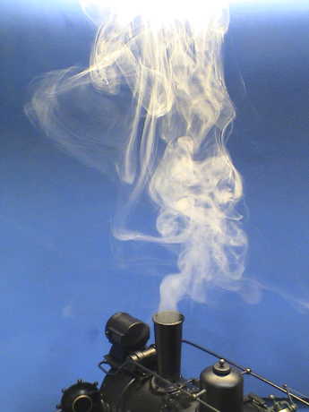 The smoke unit works quite
well, better than any other that I can recall. On a load of 10
drops of Dept. 56 Magic Smoke, it ran like this for about 10
minutes. I also used the last 5 or so drops of my San-Val Magic
Smoke and it didn't work quite as well, but still it smoked better
than most.
The smoke unit works quite
well, better than any other that I can recall. On a load of 10
drops of Dept. 56 Magic Smoke, it ran like this for about 10
minutes. I also used the last 5 or so drops of my San-Val Magic
Smoke and it didn't work quite as well, but still it smoked better
than most.
At the GIRR Mountain Division, I had LGB and Bachmann fluids. I first tried the LGB fluid which gives good results in LGB smoke generators, but the production in the Bachmann smoke unit was dismal. There was a barely visible wisp of smoke coming from the stack. The Bachmann fluid worked better, but still not as well as the San-Val Magic Smoke or Dept. 56 Magic Smoke. I used 13 drops of Bachmann fluid and it smoked reasonably well for 20 minutes.
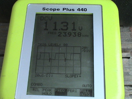
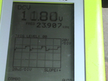 Even though the Heisler ran smoothly enough on
Aristo PWC, there were early signs of trouble. The waveform was not
right. On my little scopemeter, I could see that the waveform was
distorted and didn't return to zero between pulses. Zero is the
middle of the screen. The peaks were indeed about 20 volts as they
should have been. Further, when I switched the track to DCC to see
how it ran as an analog loco, the booster input current spiked way
past 10 amps and the booster freaked out and shut down. Something
was clearly amiss.
Even though the Heisler ran smoothly enough on
Aristo PWC, there were early signs of trouble. The waveform was not
right. On my little scopemeter, I could see that the waveform was
distorted and didn't return to zero between pulses. Zero is the
middle of the screen. The peaks were indeed about 20 volts as they
should have been. Further, when I switched the track to DCC to see
how it ran as an analog loco, the booster input current spiked way
past 10 amps and the booster freaked out and shut down. Something
was clearly amiss.
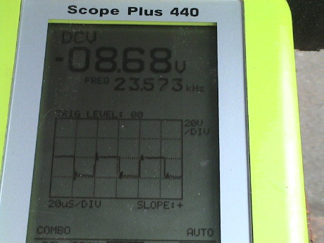 This is the waveform on the track with an
Aristo FA running. In this case, the engine is running in the other
direction so that the pulses go downward from the center, but
voltage returns to zero between pulses. There is always a little
overshoot and ringing, this is normal.
This is the waveform on the track with an
Aristo FA running. In this case, the engine is running in the other
direction so that the pulses go downward from the center, but
voltage returns to zero between pulses. There is always a little
overshoot and ringing, this is normal.
 Before I bought the Heisler, I had run across a page
on the Lake Town
and Shire railroad site that described a problem with a noise
suppression filter board in the Heisler trucks. I immediately
suspected this filter as a culprit.
Before I bought the Heisler, I had run across a page
on the Lake Town
and Shire railroad site that described a problem with a noise
suppression filter board in the Heisler trucks. I immediately
suspected this filter as a culprit.
 The filter board is obviously intended to
deal with motor noise, but since that has never been a problem for
me, it looked completely unneeded. This filter has rather large
input capacitors that probably could have just been clipped out,
but I elected to removed the whole board from each truck and splice
the wires back together.
The filter board is obviously intended to
deal with motor noise, but since that has never been a problem for
me, it looked completely unneeded. This filter has rather large
input capacitors that probably could have just been clipped out,
but I elected to removed the whole board from each truck and splice
the wires back together.
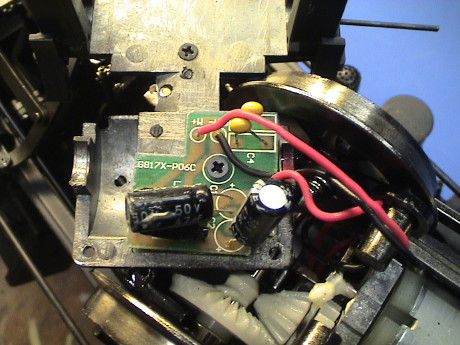
This is the truck after the filter board was
removed. The wires are tucked over the motor. There is a bulkhead
in the truck which the wires pass over. There is just enough room
between the the bulkhead and the truck bottom cover to accommodate
the wires IF they are laid flat and do not cross over each
other.
 This is the PWC
waveform on the Heisler with the filter boards gone. Also, it now
runs fine as an analog loco on the DCC system although it does make
the typical DCC hissing noise.
This is the PWC
waveform on the Heisler with the filter boards gone. Also, it now
runs fine as an analog loco on the DCC system although it does make
the typical DCC hissing noise.
 For an R/C installation, the
filter board may have some use. Instead of ripping it out like I
did, the offending capacitors can simply be clipped out. Only one
lead of either 47 µF capacitor needs to be clipped.
Alternately, both 47 µF caps can simply be discarded and one
of the 0.01 µF caps moved over to replace the larger ones.
This will make an effective balanced pi-section filter that won't
bother a DCC decoder or RC receiver.
For an R/C installation, the
filter board may have some use. Instead of ripping it out like I
did, the offending capacitors can simply be clipped out. Only one
lead of either 47 µF capacitor needs to be clipped.
Alternately, both 47 µF caps can simply be discarded and one
of the 0.01 µF caps moved over to replace the larger ones.
This will make an effective balanced pi-section filter that won't
bother a DCC decoder or RC receiver.
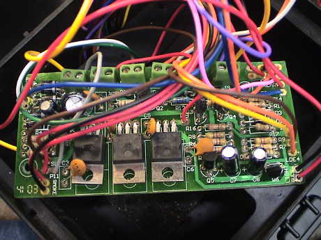
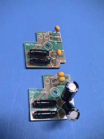 Both 0.01
µF capacitors need to be moved as shown in this photo. The
bottom board is an unmodified Bachmann board, the top one has been
changed to match the schematic. Be very careful with the solder
joints on the other side of the board. They have to be clipped very
close to the board so that the tail won't short against the metal
cover of the trucks.
Both 0.01
µF capacitors need to be moved as shown in this photo. The
bottom board is an unmodified Bachmann board, the top one has been
changed to match the schematic. Be very careful with the solder
joints on the other side of the board. They have to be clipped very
close to the board so that the tail won't short against the metal
cover of the trucks.
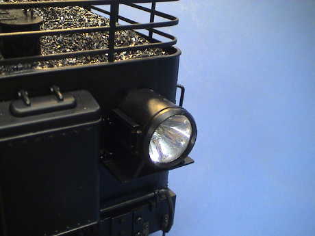
 The roof
mounted rear headlight is 1/8" too tall to fit on the GIRR Mountain
Division so it had to be moved.
The roof
mounted rear headlight is 1/8" too tall to fit on the GIRR Mountain
Division so it had to be moved.
The cab roof is attached with 6 very small screws, 4 across the front and two on the sidewalls at the rear. Once the screws are removed, the roof can simply be lifted off.
The headlight assembly is attached to the roof with two small screws and connected via contact tabs. The strips running down the left side of the cab roof support are for the headlight, the ones on the right are for the cab light. The rear headlight wires can be unsoldered from the contact tabs and the entire headlight assembly can be removed
 I also wanted to remove and
replace the yellow LED with a bright white LED. To do this the
headlight must be disassembled. The lens on mine popped out after
tapping the assembly, lens down, on my workbench. Then the
reflector and LED can be pulled out. If the lens won't budge by
itself, then a jeweler's screwdriver can be inserted in the hole
that the wires come out, BEHIND the wires, and used to force the
headlight assembly out of the housing.
I also wanted to remove and
replace the yellow LED with a bright white LED. To do this the
headlight must be disassembled. The lens on mine popped out after
tapping the assembly, lens down, on my workbench. Then the
reflector and LED can be pulled out. If the lens won't budge by
itself, then a jeweler's screwdriver can be inserted in the hole
that the wires come out, BEHIND the wires, and used to force the
headlight assembly out of the housing.
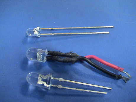
Note that Bachmann's LED (the one in the middle) has a 5 mm diameter lens, but it is shorter than a standard 5 mm LED (bottom). The standard one won't fit, it is too long and the lens won't go back on. I used a smaller 3 mm version (top).
The headlight intensity is low. I thought that this might be due to limited current supplied by the circuits on the main PWB. Once I find the correct resistors, I'll change their value to set the current between 15 and 20 mA.
 I remounted
the assembly on the rear of the tender with Zap-A-Gap CA using the
single grab iron on the engineer's side as a support. It won't be
effective in shining over the top of a train, but at least it won't
get whacked off by some low hanging feature on my layout.
I remounted
the assembly on the rear of the tender with Zap-A-Gap CA using the
single grab iron on the engineer's side as a support. It won't be
effective in shining over the top of a train, but at least it won't
get whacked off by some low hanging feature on my layout.
After I got it all back together, I went digging into the circuit board to find out why the current was low. I expected to find a current limiting resistor that set the LED current to 5 mA or less. What I found was an 820 ohm resistor and a diode running from rectified and filtered track power which should have set the current at about 18 mA. I measured the current and it was 18 mA. Then I wired one of my standard 5 mm LEDs in series with the rear headlight so that the two LEDs would draw the same current and I found that the 3 mm LED just wasn't hacking it. It was MUCH dimmer than the 5 mm LED. Clearly, I needed to get the 5 mm LEDs in there.
After I had remounted the rear headlight, I couldn't get the leverage on the back of the LED assembly to push it out anymore. Instead, I used a very small drill (0.032") chucked in a pin vice to drill a hole at the very edge of the reflector and then used the drill to pull the lens out.
To make room for the larger LED, I drilled out the hole in the reflector with a 0.200" drill bit (by hand) and inserted the 5 mm LED in from the backside. There is a protrusion on the back of the reflector which appears to have no purpose and needs to be clipped off. The flange on the back of the LED lens is larger than 5 mm so it indexes to the back of the reflector. I glued the LED to the back of the reflector with a very small amount of Zap-A-Gap and wired it in place. Glue it BEFORE you bend or clip the leads so that it will sit straight in the hole with the lens facing down against your workbench. Problem fixed.
 The trucks are already wired for DCC so
that there are 4 contacts between the frame and each truck. We'll
see later what the electrical characteristics of these contacts
are. They weren't so good on the Climax.
The trucks are already wired for DCC so
that there are 4 contacts between the frame and each truck. We'll
see later what the electrical characteristics of these contacts
are. They weren't so good on the Climax.
 There is a printed wiring
board in the tender that contains much of the circuitry. Much of
the wiring harness comes here. The only wires that don't are the
motor wires leading to the front truck. These come from the
reversing switch behind the smokebox door.
There is a printed wiring
board in the tender that contains much of the circuitry. Much of
the wiring harness comes here. The only wires that don't are the
motor wires leading to the front truck. These come from the
reversing switch behind the smokebox door.
Wiring diagrams are provided with the locomotive, but they do not include schematics of the printed wiring boards themselves. The wire colors listed on Bachmann's diagrams appear to match the loco, which is good.
I have traced out the main PWB. It contains three 12 volt regulators, the circuitry to drive the firebox flicker and some power control circuits for the cab lights and smoke. All of the wiring is interconnected on this board so that rooting out the harnesses to add DCC, R/C and or sound is not necessary. It's all here in the tender.
Installation of DCC should be pretty straightforward but I was initially confused by the Bachmann supplied drawings. Once I got their drawing conventions straight I could make sense of the tables supplied. It would have been nice had Bachmann elected to use the standard DCC color scheme for the wiring, but they didn't.
Overall, this is how the locomotive is wired. Track power is fed to the main PWB and then back to the motor reversing switch (behind the smokebox door) where it is then sent back to the motors. Track power is also rectified and filtered and used to provide a +20 volts (or so) main power bus. There are three 12 volt regulator IC's. U1 is for the smoke system. It is powered via the gray wire connected to terminal 11 or via a DCC function output connected to terminal 4. It is not active unless the smoke switch is on or terminal 3 is pulled down. U2 powers the flicker circuit and is on all the time. U3 provides power for the cab light. U3 is alternately powered via red wire on terminal 9 or by the DCC function connected to terminal 3. The headlights are connected to the +20 volt bus through current limiting resistors and are returned to the motor leads to provide directionality. One light goes to one motor lead, the other goes to the other motor lead. This is done so that the headlight direction sense will follow the motors when the direction switch is changed. When the headlights are connected to DCC decoder functions, the decoder determines which headlight is on.
The following table is my interpretation of the functions of each of the 12 screw connections on the main board and how they would be used to install a DCC decoder or R/C receiver.
| Terminal Number | Stock Wire Color | Function | DCC Connection | Notes |
|---|---|---|---|---|
| 1 | Yellow | Rear Headlight | Yellow wire removed from terminal 1 and wired to F0r | Decoder blue wire is not used to power the headlights |
| 2 | Purple | Front Headlight | Purple wire removed from terminal 2 and wired to F0f | |
| 3 | n/a | Cab Light | Connect to a decoder function output | Terminals allows the cab light to be controlled from a DCC decoder IF the Red wire at terminal 9 is moved to terminal 10. |
| 4 | n/a | Smoke | Connect to a decoder function output | This function bypasses the smoke switch so that you can turn the smoke unit on or off remotely. However, if you accidentally turn whatever function you assign to terminal 4 with the smoke unit dry, you could fry the smoke generator. If the Gray wire is moved from terminal 11 to terminal 12, the smokebox smoke switch will become inactive. |
| 5 | White | Motor | White wire is removed from terminal 5 and connected to a decoder motor output. | Motor power from the decoder is routed through the reversing switch. Bachmann recommends putting the switch in the NMRA position. However, set the switch so that the loco runs in the same direction as indicated by your DCC throttle. If the loco runs in the "wrong" direction when analog converted, reverse the orange and white wires going to the decoder. |
| 6 | Orange | Motor | Orange wire removed from terminal 6 and connected to a decoder motor output. | |
| 7 | n/a | n/a | Track power to a decoder | The input power to the decoder is derived directly from the track. This can also be the connection point for a sound system for a track powered loco. |
| 8 | n/a | n/a | ||
| 9 | Red | +20 volts | NC | Terminal 9 is used to power the cab light all the time via the Red wire. Move Red wire to terminal 10 for DCC so that terminal 3 can control the cab light |
| 10 | n/a | NC | Parking place for red wire when DCC decoder is installed | Red wire goes back to the PWB. |
| 11 | Gray | Smoke | NC | Terminal 11 is used to provide power to the smoke unit without a DCC decoder. Move to terminal 12 to disable the smokebox smoke switch. |
| 12 | n/a | NC | Parking place for the Gray wire if it is desirable to disable the smokebox smoke switch | Gray wire goes back to the PWB. |
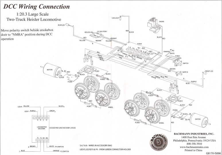
Bachmann's interconnection diagrams carry no copyright so I can duplicate them here. These show the harnessing and connections within the locomotive.
 This is the way that the
locomotive comes in the box. The average user doesn't have to
change anything. A full size version is
available as a PDF in case you lose yours.
This is the way that the
locomotive comes in the box. The average user doesn't have to
change anything. A full size version is
available as a PDF in case you lose yours.
 When rewired for DCC,
several wires are moved around. The orange/white pair that was at
terminals 5 and 6 goes to the motor output of the decoder. The
input to the decoder is at terminals 7 and 8. The yellow and blue
wires that go to the headlights come off of terminals 1 and 2 and
go to function outputs of the decoder. If you want to control the
smoke, then the gray can be left alone or it can be moved from
terminal 11 to terminal 12 and a wire is connected from terminal 4
to a function output of your decoder. If you want to control the
cab light, then the red wire at terminal 9 moves to terminal 10 and
terminal 3 is connected to a function output from the decoder.
When rewired for DCC,
several wires are moved around. The orange/white pair that was at
terminals 5 and 6 goes to the motor output of the decoder. The
input to the decoder is at terminals 7 and 8. The yellow and blue
wires that go to the headlights come off of terminals 1 and 2 and
go to function outputs of the decoder. If you want to control the
smoke, then the gray can be left alone or it can be moved from
terminal 11 to terminal 12 and a wire is connected from terminal 4
to a function output of your decoder. If you want to control the
cab light, then the red wire at terminal 9 moves to terminal 10 and
terminal 3 is connected to a function output from the decoder.
A full size version of this diagram is available as a PDF.
I spent some serious effort diagramming the schematic of the Heisler's main PWB. Where there are no part values or reference designators, I couldn't see them. I've broken the main PWB schematic into four sections. Except for the +20 volt bus and internal ground that runs through the board, these four sections are pretty much independent.
 Track power is delivered to the
board and rectified and filtered. It is then distributed through
the board as a +20 volt bus. The headlights are powered off this
bus via diodes and current limiting resistors. The headlight
returns are brought back to the motor circuit to provide for
directionality. The Rear motor is wired to the board for this
purpose. The front motor wiring is taken directly from the
reversing switch to the front motor, these are the only wires not
directly available in the tender.
Track power is delivered to the
board and rectified and filtered. It is then distributed through
the board as a +20 volt bus. The headlights are powered off this
bus via diodes and current limiting resistors. The headlight
returns are brought back to the motor circuit to provide for
directionality. The Rear motor is wired to the board for this
purpose. The front motor wiring is taken directly from the
reversing switch to the front motor, these are the only wires not
directly available in the tender.
 The cab light is normally on
all the time but by playing with the position of a red wire that
goes to terminal 9, it can be disabled and then controlled by
grounding terminal 3 via a decoder function.
The cab light is normally on
all the time but by playing with the position of a red wire that
goes to terminal 9, it can be disabled and then controlled by
grounding terminal 3 via a decoder function.
 The smoke circuit is normally
controlled by a switch behind the smokebox door. This is a good way
to leave it. However if you want to activate the smoke unit via a
decoder function, connect the function output to terminal 4. Then
either the switch or the decoder can turn the smoke unit on.
However both the switch and the decoder function have to be off for
the smoke unit to go off. To disable the manual switch, move the
gray wire from terminal 11 to terminal 12. Then the only control of
the smoke unit is via the decoder function.
The smoke circuit is normally
controlled by a switch behind the smokebox door. This is a good way
to leave it. However if you want to activate the smoke unit via a
decoder function, connect the function output to terminal 4. Then
either the switch or the decoder can turn the smoke unit on.
However both the switch and the decoder function have to be off for
the smoke unit to go off. To disable the manual switch, move the
gray wire from terminal 11 to terminal 12. Then the only control of
the smoke unit is via the decoder function.
 The firebox flicker circuits
are not remotely controllable, they run all the time. This is a
simple multivibrator that alternately flashes red and yellow LEDs
in the firebox.
The firebox flicker circuits
are not remotely controllable, they run all the time. This is a
simple multivibrator that alternately flashes red and yellow LEDs
in the firebox.
The firebox flicker may cause a problem during decoder programming as it will be a constant load on the programming track. Most DCC systems will fail to program in Paged mode with a static load present. If the cab light and smoke are wired to be controlled by a decoder, these will not be a problem but the firebox will. Unlike the Shay and Climax, it is not easy to just install a switch in series with the PWB because that would cut off power to the decoder as well.
There are three ways around this, two of them involve adding a cutoff switch. The third way involves less modification but may complicate programming a little.
One of the track power wire sets can be lifted from the PWB and fed through a switch back to the PWB. The decoder then cannot pick up power from the screw terminals, it has to be wired in BEFORE the added switch. During programming, the new switch is turned off.
Another method lifts the input terminal of U2. A wire is soldered to the board where the U2 lead was and sent to a switch. A new wire from the switch is then taken back to the input lead of U2. The switch and wire may end up being long enough to cause U2 to become unstable. A new 0.01 µF capacitor should be soldered to the input lead of U2 and ground (middle pin on U2). During programming, the new switch is turned off.
A third way is to program the address of the decoder BEFORE it is installed in the loco. All other programming can still be done in OPS mode on the main line.
 The stock
Bachmann knuckle coupler mounts typically way to low to work work
with other knuckle couplers. The Heisler is eventually going to
work on the GIRR Mountain Division which uses LGB knuckle couplers.
I don't have any LGB couplers at the GIRR to work with but the LGB
coupler and a Kadee #831 use the same mount, I initially modified
the mount for the Kadee knowing that it would be very close for the
LGB.
The stock
Bachmann knuckle coupler mounts typically way to low to work work
with other knuckle couplers. The Heisler is eventually going to
work on the GIRR Mountain Division which uses LGB knuckle couplers.
I don't have any LGB couplers at the GIRR to work with but the LGB
coupler and a Kadee #831 use the same mount, I initially modified
the mount for the Kadee knowing that it would be very close for the
LGB.
 The Bachmann knuckle
coupler that came with the Heisler is unique in my experience.
First, it is all metal. Second, it uses yet another custom coupler
mount.
The Bachmann knuckle
coupler that came with the Heisler is unique in my experience.
First, it is all metal. Second, it uses yet another custom coupler
mount.
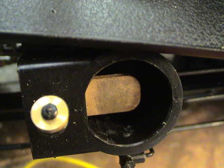
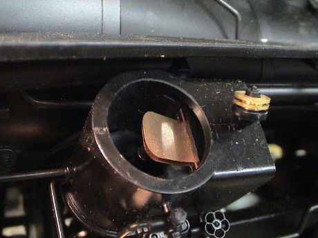
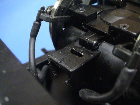 The end of the stock
coupler fits into this pocket cast into the end of the motor
blocks. It attaches with two screws and comes out easily. The bar
on the coupler is 0.384" wide by 0.253" high. The pocket is only
slight larger, but it is not completely square, it changes a little
in width deeper into the pocket. These dimensions sound very close
to 0.375" wide by 0.250" high. A built up styrene adaptor made
primarily from 0.250" by 0.125" strip stock with some thin shims to
make up the difference sounded like it would work.
The end of the stock
coupler fits into this pocket cast into the end of the motor
blocks. It attaches with two screws and comes out easily. The bar
on the coupler is 0.384" wide by 0.253" high. The pocket is only
slight larger, but it is not completely square, it changes a little
in width deeper into the pocket. These dimensions sound very close
to 0.375" wide by 0.250" high. A built up styrene adaptor made
primarily from 0.250" by 0.125" strip stock with some thin shims to
make up the difference sounded like it would work.
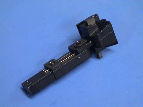
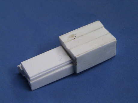 This is the initial
adaptor that I made. It's core is a 1" long piece of 0.250" x
0.125" styrene strip with a couple of 0.5" long pieces glued on the
side to make up the width. I attached a couple of pieces 0.015"
shim stock to the sides and then fit and filed until the mount was
a snug fit in the pocket. I then attached two 0.080" x 0.125"
pieces to the other end to make up the width with some 0.010"
pieces glued on to make up the 0.300" width needed to snugly fit
the couplers. I then used a razor saw to remove the part of the
center piece that was sticking up. I needed a couple of more pieces
of 0.020" shim stock to build the height back up after fitting the
adaptor to the loco. I'll probably build the 2nd one a little
differently once I get a chance to test fit an LGB coupler.
This is the initial
adaptor that I made. It's core is a 1" long piece of 0.250" x
0.125" styrene strip with a couple of 0.5" long pieces glued on the
side to make up the width. I attached a couple of pieces 0.015"
shim stock to the sides and then fit and filed until the mount was
a snug fit in the pocket. I then attached two 0.080" x 0.125"
pieces to the other end to make up the width with some 0.010"
pieces glued on to make up the 0.300" width needed to snugly fit
the couplers. I then used a razor saw to remove the part of the
center piece that was sticking up. I needed a couple of more pieces
of 0.020" shim stock to build the height back up after fitting the
adaptor to the loco. I'll probably build the 2nd one a little
differently once I get a chance to test fit an LGB coupler.
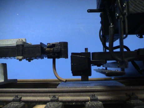
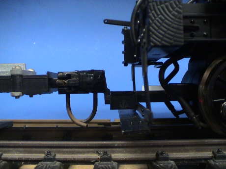 The Kadee coupler
fits on at the right height, but there is one more problem. The
mounting box for the coupler is right up next to a "board" on the
step and the truck will not be able to rotate much. The step
assembly is also metal and I don't want to cut a clearance in it
until I see how the LGB coupler is going to fit.
The Kadee coupler
fits on at the right height, but there is one more problem. The
mounting box for the coupler is right up next to a "board" on the
step and the truck will not be able to rotate much. The step
assembly is also metal and I don't want to cut a clearance in it
until I see how the LGB coupler is going to fit.
The Kadee coupler could be made to fit without cutting the step by pushing it out 1/8" and grinding off the back corners of the mounting box to allow some clearance. Another way to mount a Kadee coupler would be to use a short box body mount coupler with the large offset coupler and mount the whole box BEHIND the step. This would also bring the coupler much closer to the loco.
 The LGB
coupler did almost fit. I needed to shim it downward by 40 mils,
but it was at the right height. However, it was also resting on
part of the footrest. This prevented the truck from being able to
rotate up and down to cover track irregularities and the loco did
develop some derailment problems.
The LGB
coupler did almost fit. I needed to shim it downward by 40 mils,
but it was at the right height. However, it was also resting on
part of the footrest. This prevented the truck from being able to
rotate up and down to cover track irregularities and the loco did
develop some derailment problems.
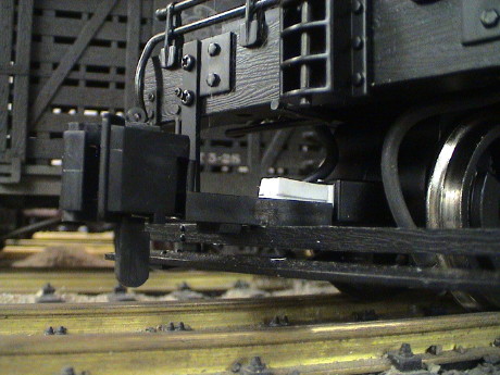
 Since I
couldn't grind on the coupler to provide clearance, I ground off
the top 2/3 of the board on the back of the step. The step assembly
is metal, but the stuff is not too hard so that it grinds fairly
easily with a Dremel tool with a milling tool. File to fit, paint
to match and it's done.
Since I
couldn't grind on the coupler to provide clearance, I ground off
the top 2/3 of the board on the back of the step. The step assembly
is metal, but the stuff is not too hard so that it grinds fairly
easily with a Dremel tool with a milling tool. File to fit, paint
to match and it's done.
The rear coupler was done pretty much the same way except I did build the mount a little differently and it has to be a quarter inch longer to put the coupler in the same position relative to the step.
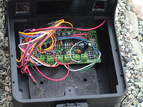 The tender is the only reasonable place to
install additional electronics such as a DCC decoder and/or a sound
system. All of the necessary connections are here already plus
there is some room although, not a lot of it. The chuff switch
wires are also here (the ones tied in a knot), but the installed
chuff switches are not very useful. The wires will be handy though
as one pair can be rerouted from a cylinder to a reed switch under
the firebox so that new wires don't have to be pulled.
The tender is the only reasonable place to
install additional electronics such as a DCC decoder and/or a sound
system. All of the necessary connections are here already plus
there is some room although, not a lot of it. The chuff switch
wires are also here (the ones tied in a knot), but the installed
chuff switches are not very useful. The wires will be handy though
as one pair can be rerouted from a cylinder to a reed switch under
the firebox so that new wires don't have to be pulled.
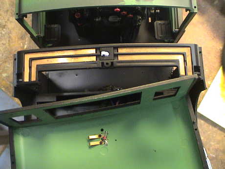
Some additional room can be had with a little hacking. First, the weight has to go. It isn't very heavy in the first place and it's weight will be, at least partially, made up from a speaker and sound system battery. If more replacement weight is needed, fishing weights can be attached to the tender walls to make up the difference. The weight is attached with two screws accessible from under the tender.
There is a boss at the top rear center of the tender opening. This is used to screw down the coal load and to help secure the rear of the tender. However, it sticks right out there and consumes some valuable real estate. The coal load fits in pretty tightly anyway and doesn't really need to be attached with a screw (accessible under the water hatch). Once the screw is abandoned, then the boss and the metal post under it can be removed as well. The post is attached by yet another screw under the tender shell. The boss itself can be simply cut off. This frees up some significant space across the back of the tender. Then the bottom of the water hatch cavity can be cut off the back of the coal load. The oil burners likely have some similar attachment point for the oil tank.
With these obstructions gone, a sound system battery can be installed down on the tender floor or maybe along a side wall. The sound board itself can either be attached to the battery, or if the speaker hangs too low, attached to a tender wall. Then there will just be two wires leading to the speaker which can be hung from the back of the coal load. The coal load would need to be drilled to provide a sound outlet and then the holes disguised with chunks of simulated or real coal. There is also a fairly large slot in the tender floor (under the PWB) that should be sealed off so that the tender shell can act as a speaker enclosure.
If a rectangular speaker is available (like the ones that Aristo uses) then the speaker could be installed on the tender floor pointing down and the sound system installed on the back of the speaker. The slot in the tender floor will still need to be sealed.
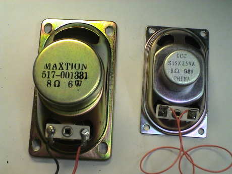 I ordered a
Soundtraxx Sierra to install into the Heisler. It's a Climax
version and it came with a small rectangular speaker. Like the
installation that I did in the Climax, I want to use a larger
speaker. I still have several of these larger ones that I bought at
a swap meet some time back. It is a standard computer speaker which
is the same size as the Aristo speaker, although this one handles
more power.
I ordered a
Soundtraxx Sierra to install into the Heisler. It's a Climax
version and it came with a small rectangular speaker. Like the
installation that I did in the Climax, I want to use a larger
speaker. I still have several of these larger ones that I bought at
a swap meet some time back. It is a standard computer speaker which
is the same size as the Aristo speaker, although this one handles
more power.
 The small speaker fits right down on the tender floor without
interference with any internal features. This would be the easiest
install, but this little speaker just doesn't sound nearly as good
as the larger one.
The small speaker fits right down on the tender floor without
interference with any internal features. This would be the easiest
install, but this little speaker just doesn't sound nearly as good
as the larger one.
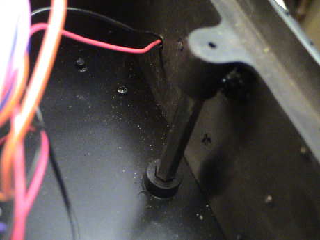 To even
get the larger speaker in place, this post has to go. This is
actually the rear attachment that holds the cab/tender shell to the
floor. The screw in the coal load must be in place for this post to
do anything. However, there are plenty of fasteners already and
when the post is removed, there is no problem with the tender shell
attachment.
To even
get the larger speaker in place, this post has to go. This is
actually the rear attachment that holds the cab/tender shell to the
floor. The screw in the coal load must be in place for this post to
do anything. However, there are plenty of fasteners already and
when the post is removed, there is no problem with the tender shell
attachment.
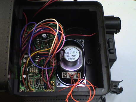
 With the post removed and the boss ground off the tender floor, the
larger speaker does indeed fit. There are three other small posts
that appear to have been there to support the cast iron weight
(which is now gone), they got ground off too. The speaker fits
between two screws that hold some of the rear detail on and the
mounting bracket for the printed wiring board.
With the post removed and the boss ground off the tender floor, the
larger speaker does indeed fit. There are three other small posts
that appear to have been there to support the cast iron weight
(which is now gone), they got ground off too. The speaker fits
between two screws that hold some of the rear detail on and the
mounting bracket for the printed wiring board.
 The PWB mounting bracket would normally allow much of the sound
energy to escape the tender out of phase with the energy directed
downward from the face of the speaker so that these large openings
need to be blocked. I attached some 0.030" thick styrene sheets
(0.5" x 4") to both sides of the bracket in an attempt to block
some of the sound from the backside of the speaker.
The PWB mounting bracket would normally allow much of the sound
energy to escape the tender out of phase with the energy directed
downward from the face of the speaker so that these large openings
need to be blocked. I attached some 0.030" thick styrene sheets
(0.5" x 4") to both sides of the bracket in an attempt to block
some of the sound from the backside of the speaker.
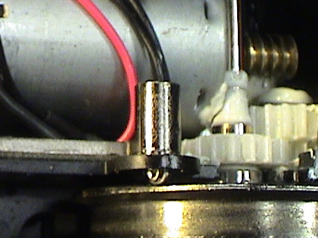
A set of contacts are on the backside of the bracket. These make contact with the contact posts that go through the tender floor. Note that the bottom in the photo is not bent like the others. This is the "inboard" motor contact which was giving me troubles. When the truck dipped downward to the front the motor would disconnect and stall. I eventually bent this contact a little to match the others and that problem went away.
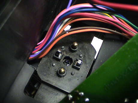 These
are the power and motor contacts for the rear truck. These press
against a small PWB that also interfaces to the contacts on the
tops of the rear truck.
These
are the power and motor contacts for the rear truck. These press
against a small PWB that also interfaces to the contacts on the
tops of the rear truck.
 The
Sierra needs an on/off switch. Soundtraxx used to provide a single
pole slide switch to switch out the battery, but it didn't actually
turn the sound system off when the user wanted silent running. This
kit came with a double pole switch so that both a battery lead and
a track lead can be switched to fully silence the system and
disconnect the battery so that it won't discharge during
storage.
The
Sierra needs an on/off switch. Soundtraxx used to provide a single
pole slide switch to switch out the battery, but it didn't actually
turn the sound system off when the user wanted silent running. This
kit came with a double pole switch so that both a battery lead and
a track lead can be switched to fully silence the system and
disconnect the battery so that it won't discharge during
storage.
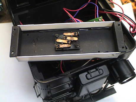
I have elected not to use the supplied battery as it is just too big to fit nicely without major surgery. Besides, it would last only a couple of years anyway. There is room above this switch for two AA NiMH cells attached horizontally to the tender wall above the switch. The other three cells mount in the same location on the other side.
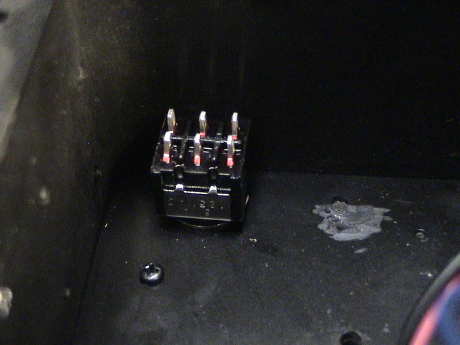
 I
mounted the switch through the tender floor on the fireman's side
where is is easy to reach but not too visually obtrusive.
I
mounted the switch through the tender floor on the fireman's side
where is is easy to reach but not too visually obtrusive.
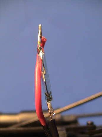 The next challenge is the chuff trigger. The Sierra has voltage
sensing autochuff mode, but overall it doesn't work very well. The
system really needs a chuff trigger. SInce I disabled the chuff
trigger switches that Bachmann provided to get rid of the
associated noise, I need to provide another source of a chuff
trigger. I unsoldered the wires from one of the existing chuff
switches and pulled them back out so that they were accessible from
the bottom of the loco.
The next challenge is the chuff trigger. The Sierra has voltage
sensing autochuff mode, but overall it doesn't work very well. The
system really needs a chuff trigger. SInce I disabled the chuff
trigger switches that Bachmann provided to get rid of the
associated noise, I need to provide another source of a chuff
trigger. I unsoldered the wires from one of the existing chuff
switches and pulled them back out so that they were accessible from
the bottom of the loco.
Soundtraxx provides a reed switch and two high energy magnets for this purpose. However, this switch is VERY fragile. DO NOT bend the leads or you will likely break the switch. I wire them this way with both wires coming from one end. The excess switch lead material can be trimmed off, but hold the switch body in your fingers when you trim lead. The shock of shearing the lead can produce enough energy to shatter the switch. Damping the shock by holding the switch body between your fingers allows the leads to be trimmed safely.
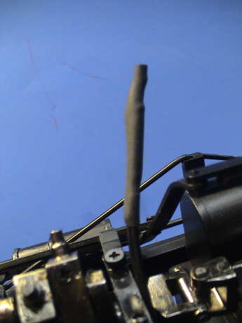 After encapsulation in some shrink tube, the switch is now fairly
sturdy. It is also easy to hold and can be fit into fairly tight
spots.
After encapsulation in some shrink tube, the switch is now fairly
sturdy. It is also easy to hold and can be fit into fairly tight
spots.
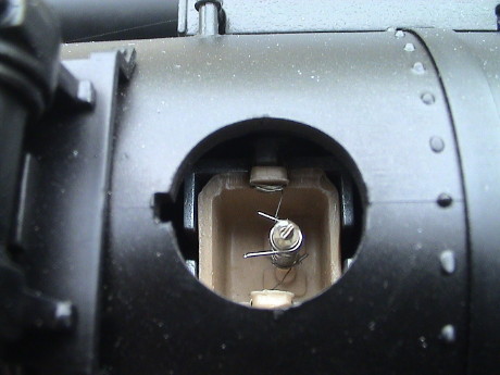
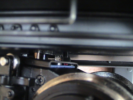
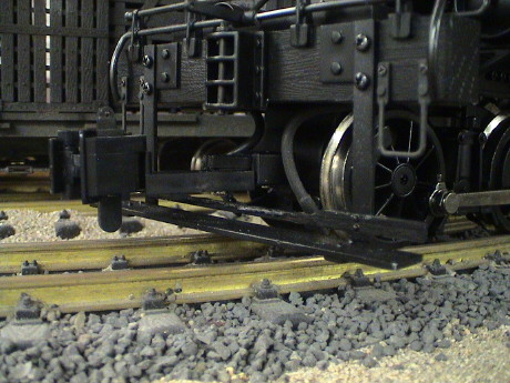
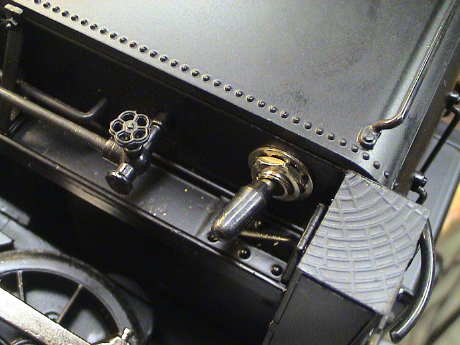
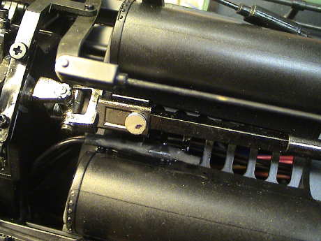 The
best place to mount the trigger magnets is on opposite sides of the
sliding square coupling to the rear truck. The chuff switch is then
attached with adhesive into the well between the ashpans. The
switch and magnets are virtually invisible in this location. With
just two magnets, the chuff rate is half the prototypical rate, but
the Sierra really can't keep up with a prototypical chuff rate
anyway. However, adding two more magnets would be easy and the
square coupling times the chuffs perfectly.
The
best place to mount the trigger magnets is on opposite sides of the
sliding square coupling to the rear truck. The chuff switch is then
attached with adhesive into the well between the ashpans. The
switch and magnets are virtually invisible in this location. With
just two magnets, the chuff rate is half the prototypical rate, but
the Sierra really can't keep up with a prototypical chuff rate
anyway. However, adding two more magnets would be easy and the
square coupling times the chuffs perfectly.
That was enough for one evening, besides I needed to let the Zap-A-Gap CA that holds the magnets on to set up completely. Those things really want to jump around if given the chance.
I still need to drill the tender floor and attach the speaker. I'll them assemble and wire the battery. The Sierra itself will mount with foam tape on the back of the speaker. Wiring the Sierra will be dead simple. There are only eight wires that will connect to the Sierra, two to the speaker, two to the track (terminals 7 and 8 on the PWB, two to the battery and two to the chuff switch. One wire to the track goes through one pole of the switch and one lead from the battery goes through the other pole. There is no need to install volume control or programming switches as the Sierra itself can be accessed directly by lifting the coal load.
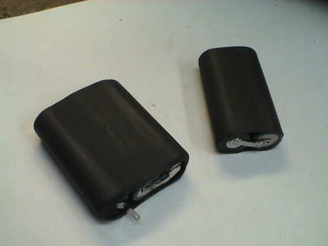 The battery
is assembled in two pieces to fit better. Two cells fit in 1"
shrink tube nicely, three cells fit in 1-1/2" shrink tube. They
attach to the sidewalls of the tender with hot glue.
The battery
is assembled in two pieces to fit better. Two cells fit in 1"
shrink tube nicely, three cells fit in 1-1/2" shrink tube. They
attach to the sidewalls of the tender with hot glue.
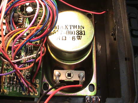
 The
tender floor is drilled with an array of 1/4" holes and the speaker
is mounted flat to the floor with hot glue on the cardboard seal.
The Sierra itself is mounted on the back of the speaker magnet with
double back foam tape. Once all the bits and pieces are mounted,
the wiring is easy following the connection diagram in the Sierra's
manual.
The
tender floor is drilled with an array of 1/4" holes and the speaker
is mounted flat to the floor with hot glue on the cardboard seal.
The Sierra itself is mounted on the back of the speaker magnet with
double back foam tape. Once all the bits and pieces are mounted,
the wiring is easy following the connection diagram in the Sierra's
manual.
The installation worked right off except that I had to reverse the track wires to terminals 7 and 8 on the Sierra to get the start whistle signals to sound properly. Programming is also necessary, a Sierra usually blows the whistle much too often so this needs to be toned down. The bell start and stop levels usually need to be set but first the battery has to charge. I turned the Heisler's motors off with the switch behind the smoke box and left the loco sitting on powered track for several hours before doing the final programming and clean up.
The coal load needed a bit of modification as well. The section under the water hatch sticks down too far and interferes with the Sierra so I ground off the extension of the water hatch below the level of the inside of the coal load.
The supplied gelcell battery comes with a pretty good state of charge. My NiMH pack was completely discharged so that the Sierra worked pretty hard to charge it. The regulator IC, the one with five leads, ran very hot for hours pumping charge into the battery. With Aristo PWC on the track set to just above the bell shutoff voltage, the area of the regulator was running about 180°F. It appears that the hottest part is the bridge rectifier at the input. It's the little square black 4 leaded black package near terminals 7 and 8. At full track voltage, it was running 230°F as measured on an IR thermometer. It'll take the Sierra more than 24 hours to fully charge the NiMH pack at the reduced track voltage. Full charge is indicated by the temperature of the regulator, once it starts to run cooler, the battery is charged.
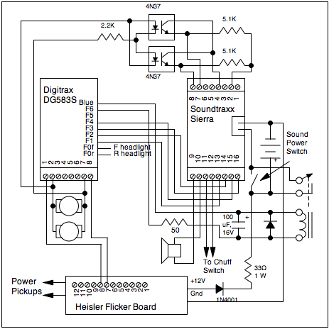
The Heisler is intended to run on the GIRR Mountain Division which is currently a track powered layout. However, I am considering converting the layout to DCC. I'd have a total of 14 locomotives to convert, several with Soundtraxx Sierra sound systems. I wanted to see how a more modern DCC decoder interacts with the Sierra, especially when running analog converted.
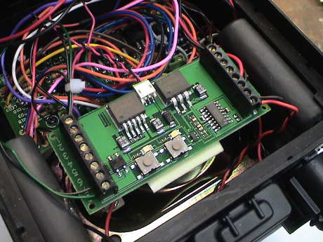
 This is the
completed DCC installation in the Heisler. Instead of the just the
Sierra mounted on the back of the speaker, I mounted a piece of
0.060" thick styrene on the speaker and then mounted the Sierra, a
Digitrax DG583S DCC decoder and a small interface board on the
styrene sheet with Velcro.
This is the
completed DCC installation in the Heisler. Instead of the just the
Sierra mounted on the back of the speaker, I mounted a piece of
0.060" thick styrene on the speaker and then mounted the Sierra, a
Digitrax DG583S DCC decoder and a small interface board on the
styrene sheet with Velcro.
The decoder installation was a piece of cake. I basically used the table shown above to determine the necessary wires to move around and it worked the first time. I did have some difficulty with getting the loco to move in the same direction as the headlights indicated. Bachmann recommended that the switch in the smokebox door be set to the NMRA standard position (engineer's side) but that messed up the analog converted direction. After a considerable amount investigation, I found that Digitrax had reversed the functions of the white and yellow wires which is in conflict with their wire color standards and the DG583S documentation. After using the yellow wire for the front headlight, the headlight, engine direction, throttle indication and the CV's used to program the effects of the headlight all worked properly.
Soundtraxx has updated their Technical Note #7 for DCC installations. One of the examples is for a DG383AR decoder, very similar to the DG583S. The DG383AR is a 3 amp decoder designed for plug and play installation in Aristo 2 motor diesels. I have one of these in my RDC. The DG583S decoder is a 5 amp unit with screw terminals intended for more general installations. Again, Soundtraxx shows the Sierra directly connected to the motor. I suspected that this would not work. However, the DG583S does have a ground terminal and so does the Sierra. The claim is that connecting the decoder ground to the Sierra ground would allow the Sierra to properly detect the starting and stopping of the loco. My money said that it wouldn't work and it didn't. I had to optically isolate the decoder motor output and the Sierra input to get the automatic start and stop signals to work.
Soundtraxx recommended that a voltage regulator be used to power the Sierra running from the decoder blue wire. Their recommendation also ditches the battery in favor of lots of charge storage in front of the regulator. Putting a big capacitor on the rectified track bus has not been a good plan when using Digitrax decoders. The very fast Schottky diodes in the newer Digitrax decoders make some pretty good spikes. These see the very low impedance of the capacitor which results in some pretty hefty current spikes. These current spikes can tend to freak out even large boosters driving the track and cause them to shut down. Bachmann is having big problems with their K-27 right now for this very reason. I elected not to fight this problem and did it another way.
 The
Heisler already has a 12 volt regulator in it that does nothing but
flicker the firebox LEDs so it has capability to handle running the
Sierra. This regulator doesn't have much charge storage so that it
cannot keep the Sierra running through momentary power dropouts.
Since I also want this loco to run on analog power, at least for
awhile, I kept the battery. The presence of the battery eliminates
any power drop out issues. I used the 12 volt regulator on the
flicker board to act as a battery charger. The Sierra actually runs
from the 5 cell NiMH battery pack that I used to replace the stock
Sierra battery.
The
Heisler already has a 12 volt regulator in it that does nothing but
flicker the firebox LEDs so it has capability to handle running the
Sierra. This regulator doesn't have much charge storage so that it
cannot keep the Sierra running through momentary power dropouts.
Since I also want this loco to run on analog power, at least for
awhile, I kept the battery. The presence of the battery eliminates
any power drop out issues. I used the 12 volt regulator on the
flicker board to act as a battery charger. The Sierra actually runs
from the 5 cell NiMH battery pack that I used to replace the stock
Sierra battery.
I also added a DCC function controlled relay in parallel with the sound power switch so that the decoder can actually enable the sound. This also causes the sound to shut off when the track power goes away so that I don't accidently leave the Sierra on and discharge the battery.
Also, I used optical isolators between the motor leads and the Sierra to allow the Sierra to properly sense the locomotive direction and also to reliably detect when it stops. The function outputs from the DG583S trigger the Sierra reliably with a direct connection. This caused the bell to stop working because the input voltage to the Sierra is lower than the bell start voltage. However reprogramming steps 17 and 18 reset the bell to work properly. It also works properly when analog converted.
Note that there is no flicker board cutout switch in this installation. I couldn't locate a place to easily install the switch. Electrically, it would be no problem to install the switch. The green wires going to the flicker board come from one rail. They would be lifted and connected to an SPST switch. This would also disconnect power to the decoder wire connected to terminal number 8, so the wire that is going to terminal 8 per the Bachmann diagram would connect back to the switch terminal that has the green wires on it to restore track connectivity to the decoder. The other contact on the switch would be wired back to the flicker board where the green wires were. When left connected to the rails, the presence of the flicker board will cause errors to be generated on a DCC programming track. The programming will still work, just the readback from the decoder will not work. I avoided this problem by programming the decoder address BEFORE I installed it and did any additional programming in OPS mode where the presence of other loads does not matter.
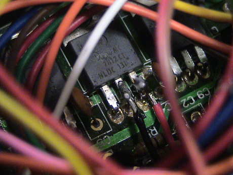 There are no
terminals that are easily accessible to pick off +12 volt and
ground from the flicker board so I tapped the power directly off of
U2, the middle regulator on the flicker board. This is the one that
runs the firebox LEDs. As measured by an IR thermometer, the
regulator runs about 150°F while sitting on DCC energized
track. This is the result of charging the battery. With the sound
system running also the temperature of the regulator goes up to
about 190°F. These numbers might sound high, but they are
pretty cool by electronics standards and pose no overstress or
reliability concerns. The 7812 has internal over temperature
protection. If it ever does get too hot, it'll shut down to cool
off. The sound system will keep running off the battery until the
7812 cools down enough to start charging the battery again. Such
shutdowns would be indicated by the loss of the flickering firebox
intermittently.
There are no
terminals that are easily accessible to pick off +12 volt and
ground from the flicker board so I tapped the power directly off of
U2, the middle regulator on the flicker board. This is the one that
runs the firebox LEDs. As measured by an IR thermometer, the
regulator runs about 150°F while sitting on DCC energized
track. This is the result of charging the battery. With the sound
system running also the temperature of the regulator goes up to
about 190°F. These numbers might sound high, but they are
pretty cool by electronics standards and pose no overstress or
reliability concerns. The 7812 has internal over temperature
protection. If it ever does get too hot, it'll shut down to cool
off. The sound system will keep running off the battery until the
7812 cools down enough to start charging the battery again. Such
shutdowns would be indicated by the loss of the flickering firebox
intermittently.
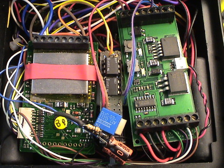
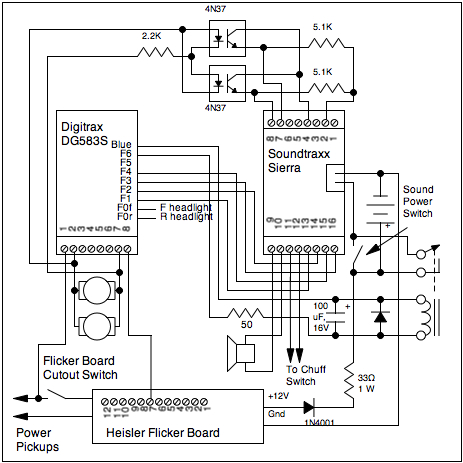
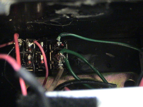 After
I started using JMRI I
wanted to have the loco work on the programming track so that JMRI
could read back the entire contents of the decoder's CVs. The
Heisler didn't work on the programming track due to the parasitic
load of the flicker board. However, there was indeed a spot for a
small switch immediately in front of the existing DPDT sound switch
if I mounted it sideways. I used an SPDT switch because that is
what I had. The handle then pushes inward to connect the flicker
board, and outward to allow programming. A little black paint on
the handle took car of the majority of the visual impact.
After
I started using JMRI I
wanted to have the loco work on the programming track so that JMRI
could read back the entire contents of the decoder's CVs. The
Heisler didn't work on the programming track due to the parasitic
load of the flicker board. However, there was indeed a spot for a
small switch immediately in front of the existing DPDT sound switch
if I mounted it sideways. I used an SPDT switch because that is
what I had. The handle then pushes inward to connect the flicker
board, and outward to allow programming. A little black paint on
the handle took car of the majority of the visual impact.
 The switch is wired
just as described above. One lead of the decoder is lifted from the
flicker board and wired back to the green track wires which were
lifted from the board. The switch is then wired back to where the
green wires went.
The switch is wired
just as described above. One lead of the decoder is lifted from the
flicker board and wired back to the green track wires which were
lifted from the board. The switch is then wired back to where the
green wires went.
[ Home ] [ Up ] [ Previous Page ] [ Next Page ]
This page has been accessed times since 18 Jul 08.
© 2008-2009 George Schreyer
Created 11 Jul 08
Last Updated May 21, 2009