 10 Sep 1121 Jan 09
 3 Dec 083 Dec 0812 Dec 08
[ Home ] [ Up ] [ Previous Page ] [ Next Page ]
10 Sep 1121 Jan 093 Dec 083 Dec 0812 Dec 08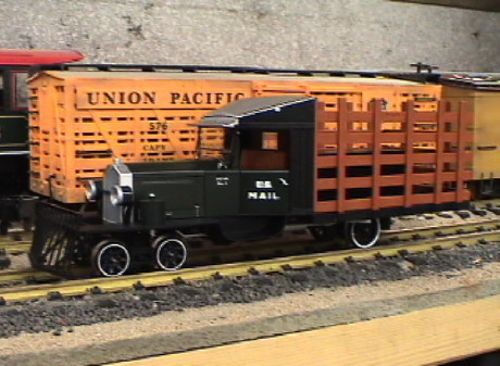 Some time ago,
Bachmann added a railtruck to their Spectrum line. Railtrucks were
adaptations of highway vehicles intended to reduce the cost of
operations on lightly traveled lines. This was a desperation move
by the railroads in an attempt to stave off bankruptcy a little
longer. Eventually, however, the inevitable happened and many rail
lines had to shut down. They just could not compete with cars and
trucks after a suitable road system had been built out. Most of
these rail vehicles were one of a kind contraptions built in the
railroad's own shops. This one is a stakebed truck used to continue
the mail contracts. It is lettered as RGS No. 1.
Some time ago,
Bachmann added a railtruck to their Spectrum line. Railtrucks were
adaptations of highway vehicles intended to reduce the cost of
operations on lightly traveled lines. This was a desperation move
by the railroads in an attempt to stave off bankruptcy a little
longer. Eventually, however, the inevitable happened and many rail
lines had to shut down. They just could not compete with cars and
trucks after a suitable road system had been built out. Most of
these rail vehicles were one of a kind contraptions built in the
railroad's own shops. This one is a stakebed truck used to continue
the mail contracts. It is lettered as RGS No. 1.
The real RGS #1 was built from a Buick Master Six Sedan in 1931 and scrapped in 1933. An operational replica was built in 2000 and is still on display. You can read more about the Galloping Goose at Rio Grande Southern Galloping Goose. A timeline for all the Geese is at Rio Grande Southern RR - Galloping Goose Timeline.
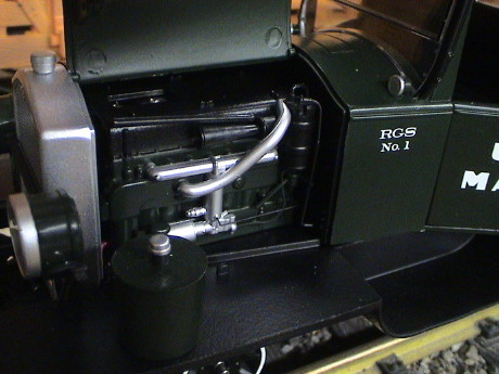 The detail on this model is
quite good. Bachmann has gone to great lengths to produce a sturdy
and good looking model. The scale is nominally 1:20.3. Even the
mechanical layout is reasonably close to the prototype. The hood
panels can be lifted to reveal an engine. The motor is under the
hood inside the shell of the engine model. One shaft of the motor
is used to drive the engine's fan. The cab is detailed with a seat,
a driver (packaged separately) and some controls such as a
gearshift lever. Under the floorboards is a gearbox where the
transmission would normally be. The rear axle is driven via a
functional drive shaft.
The detail on this model is
quite good. Bachmann has gone to great lengths to produce a sturdy
and good looking model. The scale is nominally 1:20.3. Even the
mechanical layout is reasonably close to the prototype. The hood
panels can be lifted to reveal an engine. The motor is under the
hood inside the shell of the engine model. One shaft of the motor
is used to drive the engine's fan. The cab is detailed with a seat,
a driver (packaged separately) and some controls such as a
gearshift lever. Under the floorboards is a gearbox where the
transmission would normally be. The rear axle is driven via a
functional drive shaft.
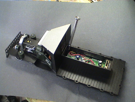
The bed has a large box in the middle which is used to house the electronics. There are yellow LEDs in the headlights which simulate the normally weak 6 volt electrical system of these vehicles and there is a single red LED to the rear required by railroad practice. The electronics has an interface for a DCC decoder and provides reasonable constant intensity lighting when driven by Aristo's Train Engineer with PWC. The constant intensity lighting doesn't do nearly as well with linear power.
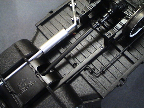
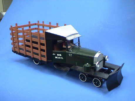 The Goose comes with an
optional snowplow that fits were the boiler tube pilot goes. It is
easy enough to install, but you have to significantly flex the
crossbar where it clips to the frame to get either one on or
off.
The Goose comes with an
optional snowplow that fits were the boiler tube pilot goes. It is
easy enough to install, but you have to significantly flex the
crossbar where it clips to the frame to get either one on or
off.
After I had upgraded the headlights to where they cast a real beam, I noticed that they shown partly through the pilot. The plow is solid and blocks much of the headlight beam so that I'm going to use the pilot instead of the plow. The Goose would not be able to do any real plowing anyway. It doesn't have nearly enough power or traction and it doesn't snow often on the indoor GIRR Mountain Division.
The running properties, however, were not so good, at least on the one that I bought. It ran fairly quietly in reverse, but made rather bothersome noises running forward as can be heard in this short H.264 movie clip of the railtruck as delivered. You'll need something like QuickTime that can decode H.264 to view the clips on this page.
On downgrades the railtruck has a serious surge as the slack in the drive train is repeatedly taken out and then builds up again. The surging is not nearly as bothersome to me as the grinding sound made by the gearbox. It sounded bad and had to be investigated before I could put any significant runtime on the railtruck.
Further, there is a gear alignment problem that would certainly result in early gear failure.
Power pickup seemed to be pretty good even though I found that one of the rear wheels did not pick up power, see a separate section below concerning this other manufacturing problem. Even before the power pickup fix, it was pretty reliable. After the fix it was quite good, I detected no tendency to stutter or stall at all on my indoor track, which is in good condition.
The railtruck handles 4 ft diameter curves (LGB R1) with no difficulty except for only a little slowing in the curves. However, it could not handle the 2 ft diameter curves on my trolly line. This should not be an issue as hardly anybody but me is crazy enough to bend track that tight.
Tracking is excellent. After some high speed running in both directions all over the GIRR Mountain Division, the railtruck didn't derail at all. Running backwards, it did consistently pick the point of one turnout, but that was the turnout's fault. A little work with a grinding wheel at the offending point fixed that problem completely.
I had heard that Dave Goodson at NorthWest Remote Control Systems had worked up a procedure for fixing a systematic manufacturing defect that afflicts part or all of the initial railtruck production. He sent me these instructions, which I followed and documented below. Even though my unit did indeed have this particular problem, Dave's fix didn't impact the running noise. Dave's fix, however, will likely prevent the railtruck from eating it's own gearing.
The basic problem is that the output gear is not properly constrained due to some incorrect screws (or perhaps due to tapped holes that are too shallow) and the meshing of the gearbox output bevel gear is uncontrolled.
Dave's instructions are in italics:
The final drive surge is single-lead worm related, and slack
in those u-joints. No real economical fix.
Dave
31JAN2006
Tearing down 5 new Railtrucks (3 here, 2 at Barry's), we have
discovered an issue which in most probability will result in
failure of the output gears in the transmission (gearbox) of this
unit.
The screws in question (from the parts breakdown list provided with the unit) are Kader Part Number SCREW-10644.
These are about .195" in length from under the head to end of threads. They need to be no longer than .150", and probably for manufacturing tolerances, about .140".
The screws are bottomed out in the holes. This prevents the keeper (Kader 00L06, I think it says) from holding the brass bearing firmly in the housing, allowing extreme wobble and gear un-mesh in the output bevel gears, which shall result in failure at some point.
Procedure:
As an addendum:
The screws provided with the snowplow are exactly the correct
length.
We are still working on the surging on grades, two paths in work at this time.
TOC
Published with permission of Bachmann Industries. This notice must be attached to any copies.
Following is a photo narrative describing my experience in making this modification. It is not difficult to do at all. The only tool that is needed is a Phillips jeweler's screwdriver although a Kadee 5-finger grabber tool is handy for holding the very small screws.
 The stakes and engine
cowls come off easily with a small amount of flexing. The side
stakes are secured to the rear of the cab by small tabs. Simply
flex the cab away from the side stakes just a little to release the
tabs.
The stakes and engine
cowls come off easily with a small amount of flexing. The side
stakes are secured to the rear of the cab by small tabs. Simply
flex the cab away from the side stakes just a little to release the
tabs.
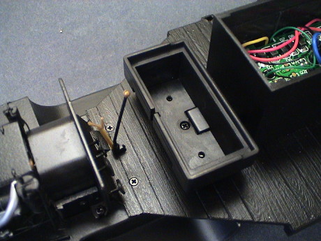
There is one screw down inside the box on the truck bed that has to come out. It is pointed to by the screwdriver in the photo. The bed box has to be able to flex upward to clear the mounting tabs for the cab so that the cab can be removed. It is safe to gently pull the front of the bed box upward while removing the cab to clear these tabs.
 The cab is released by
removing two screws underneath. One is visible, the other is hiding
in the shadow of the muffler. These screws engage lugs on the rear
of the cab that would interfere with the bed box if that one screw
in the bed box was not removed.
The cab is released by
removing two screws underneath. One is visible, the other is hiding
in the shadow of the muffler. These screws engage lugs on the rear
of the cab that would interfere with the bed box if that one screw
in the bed box was not removed.
 The two flathead screws
in the cab floor hold the floor down. The cab floor is also the top
cover of the gearbox, our objective.
The two flathead screws
in the cab floor hold the floor down. The cab floor is also the top
cover of the gearbox, our objective.
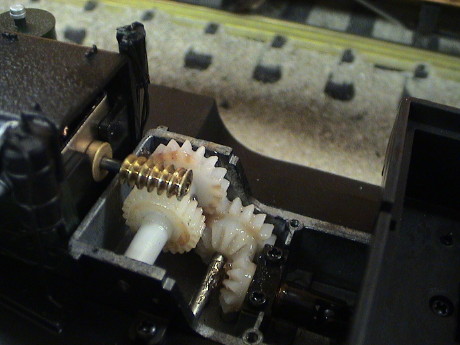 This is the gearbox. The offending
screws are the in lower part of the picture, just to the right of
center. If your railtruck has a screw problem, the keeper piece
will be loose as the longer screws have bottomed out without
bearing down on the keeper.
This is the gearbox. The offending
screws are the in lower part of the picture, just to the right of
center. If your railtruck has a screw problem, the keeper piece
will be loose as the longer screws have bottomed out without
bearing down on the keeper.
If the railtruck is run with a loose keeper, the bevel gear leading to the driveshaft will squirm around as the direction of the railtruck is shifted from forward to reverse. The imprecise position of this bevel gear will result in early failure if it is not fixed. The shorter screws supplied with the snowplow are indeed just right. Since I wasn't planning on using the snowplow anyway, it was obvious that a swap for the longer screws was the hot setup.
Note that the cab can fit back on in two ways. In the incorrect way, it sits a little too far to the rear and the hood pieces do not fit properly. If you find this problem, lift the cab and reinstall it in the most forward position that it will fit.
When I completed this fix and retested the railtruck, the noise problem was not changed as can be heard in this clip. The problem is at the motor worm. There appears to be a thrust oscillation in the motor shaft which is resulting in the noise. After I determined that the noise wasn't going to cause the gearing to self destruct immediately, I ran it for awhile and the noise reduced, but it had not gone away in a few minutes running.
If I press on the end of the worm while the railtruck is moving forward, the oscillation is damped and the noise goes away. If I lift the drive wheels from the track to remove much of the load on the drive train, the noise also goes away. If I push the railtruck forward lightly while is running slowly forward to remove the load on the drive train, the noise also goes away. When the railtruck is running downhill and it is lightly surging, the noise follows the surge. When the drive train slacks due to the surging, the noise stops.
It turned out that all it needed was some more significant run-in time to get the gearing to wear together properly. This clip shows what about an hour of running did.
The Bachmann Railtruck is susceptible to surging due to the accumulated slop in the driveline. There is a total of about a quarter drive wheel turn of play in the overall driveline all the way back to the worm. The worm itself is a single lead screw which cannot be backdriven. When running on the flat, or with a load, the slop is all taken up and the railtruck runs smoothly. However, when running downgrade, the driveline doesn't provide enough drag and the railtruck runs away due to the pull of gravity until the slop is all taken out the other way and the driveline binds up against the worm causing the Railtruck to nearly stop. As the worm gear continues to turn, it takes up the slop again and drives the railtruck downhill until the acceleration of gravity takes over again and the railtruck runs ahead of the worm. The surging due to the driveline slop can be seen in this short clip.
If a loco is placed on a grade and pushed back up until the wheels slip and it can then roll downgrade from there, it will surge to some extent on that grade. Possible solutions take two diverging paths, either the backlash has to go or the tendency to free roll has to go.
I spoke with Barry of Barry's Big Trains at the Big Train Show yesterday and he says that he has completely reworked the driveline to eliminate the slop and therefore the surging. Contact him for details.
If there is enough drag such that the railtruck cannot free roll on a downgrade, then it can't get ahead of itself and it won't surge. This can be seen in the clip when the railtruck enters the curve where the drag increases and the surging immediately stops.
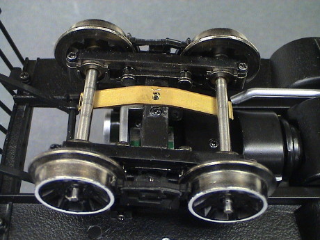 Adding drag is an inelegant hack
but it can be easily kludged and it does work as shown in this clip. I
found a piece of 0.032" x 0.250" brass strip on my workbench and I
bent a piece to act as a spring bearing against the front axles. I
had originally intended to hold it in place with the screw on the
truck, but the screw was too short and I didn't have a longer one
with the same thread. However, I found that the strip will hold
itself in place just fine. It can be placed anywhere along the
axles. The tension on the spring is somewhat critical. Too much
pressure and the front wheels will not turn. Too little and the
railtruck will still surge, but there is a sweet spot that allows
the wheels to rotate and still provides sufficient drag to stop the
surging. A technically better place to add drag would be at the
rear axle, but an easy way to implement that feature there hasn't
occurred to me.
Adding drag is an inelegant hack
but it can be easily kludged and it does work as shown in this clip. I
found a piece of 0.032" x 0.250" brass strip on my workbench and I
bent a piece to act as a spring bearing against the front axles. I
had originally intended to hold it in place with the screw on the
truck, but the screw was too short and I didn't have a longer one
with the same thread. However, I found that the strip will hold
itself in place just fine. It can be placed anywhere along the
axles. The tension on the spring is somewhat critical. Too much
pressure and the front wheels will not turn. Too little and the
railtruck will still surge, but there is a sweet spot that allows
the wheels to rotate and still provides sufficient drag to stop the
surging. A technically better place to add drag would be at the
rear axle, but an easy way to implement that feature there hasn't
occurred to me.
Note that by adding drag, the motor has to work a little harder all of the time. This causes the motor current to increase a little, from about 250 mA running on the flat to about 300 mA. If your truck has been converted to battery power, this will shorten the run time by 15% or so.
With this simple and reversible modification, the railtruck doesn't surge on my 4% grades at any speed and it still runs smoothly and quietly.
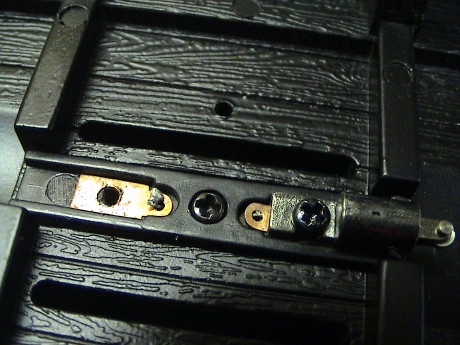 As part of my usual
locomotive testing process, I lift all the wheels but one axle's
worth, one axle at a time, from the track to be sure that all of
them are picking up power. On this model, the rear wheels did not
pick up power. I quickly traced this to bad solder joints where the
wires come down from the electronics box to the wheel contacts. One
contact has been removed in this photo, it was the bad one. The
other side also has a bad solder joint, but it was at least making
contact.
As part of my usual
locomotive testing process, I lift all the wheels but one axle's
worth, one axle at a time, from the track to be sure that all of
them are picking up power. On this model, the rear wheels did not
pick up power. I quickly traced this to bad solder joints where the
wires come down from the electronics box to the wheel contacts. One
contact has been removed in this photo, it was the bad one. The
other side also has a bad solder joint, but it was at least making
contact.
There are four screws at the corners of the rear axle structure that allow the whole rear end to be removed. It will simply slip out of the driveshaft. Upon reassembly, make sure that both ends of the driveshaft fix back into the universal joints.
The fix was a simple resolder job. However, the tabs are very lightweight metal and they sit in a plastic insulator. If you just touch them with a regular soldering iron, you'll melt them right into the plastic. First lift them off the plastic surface a little with a toothpick and then use a very fine tip soldering iron at low heat and apply a very small amount of solder to make a reliable contact.
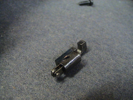 The wheel contacts themselves
are in a form that I have not seen before. They have very small
rollers that ride on the wheel back to reduce friction and noise.
The power pickups on the front wheels are the same design.
The wheel contacts themselves
are in a form that I have not seen before. They have very small
rollers that ride on the wheel back to reduce friction and noise.
The power pickups on the front wheels are the same design.
The rollers seem to work quite well. They do roll with the wheels, but there is a downside to this contact type. The roller is very small. Therefore it has to turn quite fast to keep up with the wheel. There isn't much spring tension holding it against the wheel, but there is some. Even with the light pressure, the high speeds will result in bearing wear unless the bearing is lubricated. The bearing is a simple pin, both the pin and the roller rotate so that the pin will wear both inside the roller and in the fork. If these surfaces are left unlubricated, I expect that the pins, rollers or forks will eventually completely wear through. This will happen with lubrication as well, but at a much slower rate.
Considering that the low drag contacts actually contribute to surging, Bachmann may have been better served by using conventional friction contacts.
I took the railtruck back to the outdoor GIRR and tried it. There hadn't been a train movement in three months (due to extended travel and building projects) and the track was pretty dirty. The railtruck sputtered. After several passes with a track cleaning car, the GP9 pulling it was still being impacted by the dirty track a little but the railtruck ran without a hitch, not a hint of sputter or even headlight flicker. It also ran on DCC (address 0) but it made the typical DCC hiss that all analog locos make while running at DCC address 0.
After a couple of years, the power pickup of the railtruck slowly degraded. It would tend to stall when the rear wheels were on insulated frogs indicating that the front pickup was getting worse. After a close inspection and some continuity check, the worst problem seemed to be at the front wheel contacts. The continuity to the rollers themselves was not perfect, but it was much better than the continuity to any of the wheels. I swapped the backs of the wheels with an alcohol soaked cotton swap and pulled off a deep black contamination. After rechecking the continuity, the contact was still not perfect, but it was much better. The truck also ran much better over turnouts. Things do need cleaning once in a while.
Another spot that causes problems is the connection from the front truck to the frame. There are some spring loaded contacts in the trucks that bear against a solder-plated PWB on the frame. This point of contact oxidizes after awhile and needs attention too. Since it is a major assembly job to get the front truck off, it is easier to lightly abrade the PWB surface where the contacts touch it. Access isn't good but a small tool can reach in there and half of each plate can be cleaned up a little at a time. I used the flat end of a jeweler's screwdriver to very lightly scrape the surface. A better tool would be a mildly abrasive probe, such has a carved down pencil eraser held in a tweezer to rub the surface.
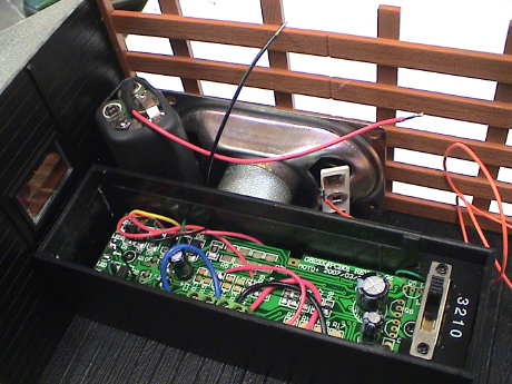
 This is the
interconnection diagram for the Railtruck as configured for track
power. I did not try to tease out the wiring of the printed wiring
board as it appeared pretty simple and the information that I
needed to proceed with a sound installation was actually all on
these drawings. Also, the board doesn't come out easily so I
couldn't get to the back of it without tearing up too much
wiring.
This is the
interconnection diagram for the Railtruck as configured for track
power. I did not try to tease out the wiring of the printed wiring
board as it appeared pretty simple and the information that I
needed to proceed with a sound installation was actually all on
these drawings. Also, the board doesn't come out easily so I
couldn't get to the back of it without tearing up too much
wiring.
A full size PDF of this image is available at the link.
The PWB itself contains a bridge rectifier and filter capacitor to provide power to the headlights and tail light which are non-directional. It also provides the interconnection points for a DCC installation. This is important to me because track power is easily accessible on terminals 1 and 2. The black and red wires that are already there go to the motor, they will stay there when these points are used to drive a sound board.
 For a DCC
installation, the red, black and blue wires are removed from
terminals 1, 2 and 3 and are instead wired to a decoder. The blue
wire (on the board, not to be confused with a decoder blue wire) is
for the headlights which are wired together internally. It is not
easy to make them directional even with a decoder as long as the
stock Bachmann PWB is retained. The black and red wires go to the
motor output of a decoder. The blue wire goes to the headlight
outputs (both forward and reverse) of a decoder. The red and black
wires on the decoder (power input) go back to terminals 1 and
2.
For a DCC
installation, the red, black and blue wires are removed from
terminals 1, 2 and 3 and are instead wired to a decoder. The blue
wire (on the board, not to be confused with a decoder blue wire) is
for the headlights which are wired together internally. It is not
easy to make them directional even with a decoder as long as the
stock Bachmann PWB is retained. The black and red wires go to the
motor output of a decoder. The blue wire goes to the headlight
outputs (both forward and reverse) of a decoder. The red and black
wires on the decoder (power input) go back to terminals 1 and
2.
A full size PDF of this image is available at the link.
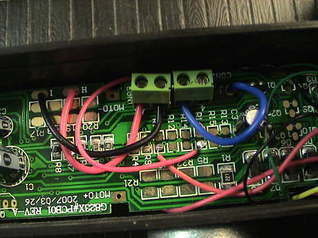 This
wire color stuff is confusing because it conflicts with the DCC
standards. The red and black wires that go from pads H and I to
terminals 1 and 2 ought to be orange and gray. The blue wire that
goes to terminal 3 ought to be white. In any event, to connect a
decoder, these three wires need to be spliced into decoder
wires.
This
wire color stuff is confusing because it conflicts with the DCC
standards. The red and black wires that go from pads H and I to
terminals 1 and 2 ought to be orange and gray. The blue wire that
goes to terminal 3 ought to be white. In any event, to connect a
decoder, these three wires need to be spliced into decoder
wires.
 I had
intended to install a Soundtraxx Sierra Goose sound system in the
railtruck. This time around, I am resigned to using a smaller
speaker. This one came in the Climax Sierra that I installed in a
Bachmann Heisler. In the
Heisler, I used a larger speaker as that sound system sounds better
with it. The goose sound doesn't have as much bass in the sound and
it can get away with a smaller speaker. Besides, there just isn't
room for a larger one.
I had
intended to install a Soundtraxx Sierra Goose sound system in the
railtruck. This time around, I am resigned to using a smaller
speaker. This one came in the Climax Sierra that I installed in a
Bachmann Heisler. In the
Heisler, I used a larger speaker as that sound system sounds better
with it. The goose sound doesn't have as much bass in the sound and
it can get away with a smaller speaker. Besides, there just isn't
room for a larger one.
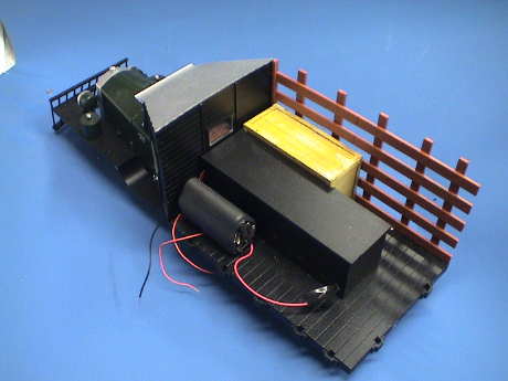
I might build an L-shaped box that looks like two crates to enclose the speaker, battery and the Sierra. The Sierra itself will sit on top of the tool box. The Sierra is slightly narrower and much shorter than the took box. The lid of the toolbox will be part of the sound system box. I'll run a pair of wires through the cover of the toolbox and put a two terminal connector inside the tool box so that the whole assembly can be removed. The sound system power switch will sit low to the floor facing rearward. Some black paint will make it less visible.
The battery is a 5 AAA NiMH set as the included Sierra gelcell battery is much too large.
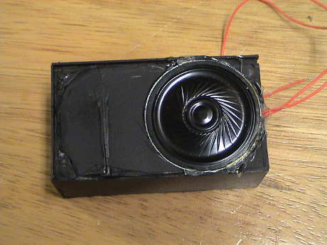
 Even
though the Sierra hadn't arrived, I went ahead and prepared the
speaker. I built up a styrene box and fashioned the visible sides
to look like a crate. I did the typical scrape with a razor saw and
blackwash tricks to simulate some wood grain.
Even
though the Sierra hadn't arrived, I went ahead and prepared the
speaker. I built up a styrene box and fashioned the visible sides
to look like a crate. I did the typical scrape with a razor saw and
blackwash tricks to simulate some wood grain.
I had originally intended to put the speaker and battery pack in the same box, then I though better of it. There would be too much weight on one side so the battery pack was rearranged slightly so that it would fit on the other side and not be so tall. The wires from the speaker fit between the cab and the tool box.
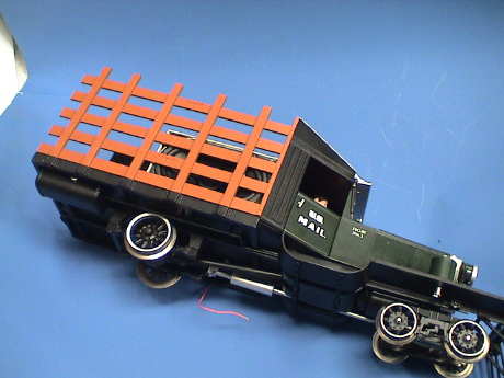 The
face of the speaker shows through the stakes. I need to find a
scrap of thin cloth about the same color as the crate to make a
grill for it.
The
face of the speaker shows through the stakes. I need to find a
scrap of thin cloth about the same color as the crate to make a
grill for it.
While I was pondering exactly how to mount the Sierra it's delivery date kept slipping out. As of Sept 08 there was some information out that Soundtraxx was cancelling the Sierra entirely. By a week later it was official. Soundtraxx had cancelled the Sierra. I needed a replan.
Since plan A was already dead, I settled on Plan B and ordered a Tsunami not realizing that it was also unobtainable. It's four months later and I have the answer on the Tsunami, NOT. Soundtraxx has elected NOT to make the TSU-1000 with a Goose sound, further they have changed the specs and the ratings changed such that a TSU-1000 is not rated with sufficient stall current to drive a railtruck. Therefore I went Plan H and ran in stealth mode with a DH123 DCC decoder.
However, by January 2009, I had installed an ESU LokSound V3.5 sound decoder in a Bachmann Davenport. The ESU was a little more expensive than the Tsunami, but not by a lot. It also worked very well indeed in the Davenport which is more demanding on the motor controller. The ESU LokSound does indeed provide enough sound volume. Although the volume not as loud as more traditional large scale sound systems, it is just adequate. Therefore I am going with Plan I and I ordered an HO LokSound for the railtruck. I will pull the oval speaker out of the box I made and put a 40 mm round 100Ω speaker in. I have another use for the DH123 DCC decoder that is in there now. Plan K with a Dallee board would have been a wash cost wise because I'd need a slightly more expensive decoder with enough function outputs to trigger the Dallee sounds AND the LokSound DCC decoder is a lot better decoder than a DH163.
| Sound System | Motor Control | Cost | Notes | ||
|---|---|---|---|---|---|
| Sound | DCC | ||||
| Plan A | Soundtraxx Sierra | PWC track power | $140 | n/a | Sierra is no longer available. Is kind of large but I could have made it fit. It USED TO BE available with Goose sounds. |
| DCC | $140 | $16 | Digitrax DH123 decoder. Also would need to build a special interface circuit to get the motor speed to ramp properly, see Sierra Tips for details. | ||
| Plan B | Soundtraxx Tsunami | Track Power or DCC | $95 | n/a | Tsunami is a combo DCC decoder and sound system, but it will run analog converted pretty well. However, the current TSU1000 is an HO rated decoder and MAY not survive on large scale track voltages. Anecdotal evidence exists of fried or shutdown decoders from some experienced DCC users. Tsunami may eventually come with Goose sounds. |
| Plan C | Soundtraxx DSX | DCC only | $50 | $16 | Use a cheap DCC decoder and DSX sound decoder. DSX has a tendency to be flakey on dirty track and hurts for adequate audio power, but it has Goose sounds. |
| Plan D | Phoenix P5 | PWC track power | $145 | n/a | requires additional adaptor board, cost TBD, to work with analog power. Doesn't carry a battery so it won't run at all until the railtruck is already moving. P5 comes with Goose sounds. |
| DCC | $145 | $16 | Combo works pretty well, somewhat sensitive to dirty track, see P5 Tips. P5 has rudimentary DCC controls in it to allow sounds to be played from a DCC throttle | ||
| Plan E | Phoenix 2K2 | PWC track power | $250 | n/a | Carries it's own battery and works quite well on track power, but is expensive. Comes with Goose sound. |
| DCC | $250 | $16 | 2K2 has rudimentary DCC controls in it to allow sounds to be played from a DCC throttle. On board battery makes it immune to dirty track problems. About the same size as the Sierra but won't require the interface circuitry that the Sierra would. 2K2 is also somewhat large, but would fit in a simulated crate on the bed. | ||
| Plan F | QSI | DCC only | $150 | n/a | Sound integrated with a DCC motor controller. DOESN'T have Goose sounds, at least yet. Would have to make do with some other sound file, not a very attractive option. |
| Plan G | Digitrax Soundbug | DCC only | $50 | $16 | Not available with Goose sounds, Unknown how it handles large scale track voltages. SoundBug hurts for audio output power. |
| Plan H | None | PWC track power | $0 | $0 | cheapest option until something better comes along |
| DCC | $0 | $16 | The whole layout has been converted to DCC and the railtruck is the only loco that is not converted to DCC already. | ||
| Plan I | ESU LokSound | DCC or analog | $110 | n/a | Has excellent Goose sounds. Uses an odd 100 ohm speaker but provides adequate volume with an $8 40 mm speaker. |
| Plan J | ESU LokSound XL | DCC or analog | $185 | n/a | Has excellent Goose sounds. 1.5 watt audio output and will drive an 8 ohm speaker but expensive. |
| Plan K | Dallee Goose | DCC or analog | $95 | $23 | Has available Goose sounds. 2 watt audio output and will drive an 8 ohm speaker. The board is about the same size as most of the other standalone sound systems but requires outputs from a DCC decoder to drive the sounds. A DH123 doesn't have enough function outputs, need to go to a slightly better decoder |
For some reason Bachmann choose to place the "toolbox" which contains a PWB and a lot of wiring right in the middle of the bed. It uses up all the prime real estate back there. They could have made one that sat crosswise at the front that would have been much less intrusive. Instead we are left with this blob right where other stuff, like electronics and batteries, could go. As it is there is enough room inside the box for a small DCC decoder/sound combo, but nowhere close to enough room for batteries and an RC RX if desired unless the PWB was removed. It then might be big enough to hold a small battery pack and an RX.
I haven't decided if I am going to nuke the box yet, there might be enough room inside for a LokSound decoder and I've already built a good speaker enclosure that fits in a "crate" next to the toolbox but I looked into jettisoning the toolbox anyway.
The PWB itself has very little value added if a DCC decoder or RC system is installed. The railtruck only has a motor and three LEDs. None of the support circuitry on the PWB is really needed if more capable electronics are installed so it can easily go overboard. With DCC or RC installed, the switch isn't needed either. So if the PWB can go, so can the box. Removal of the box is quite easy.
 At this point, there
are wires several loose wires leading up from the truck body, these
can be identified from the wiring diagrams above. There are also
two mounting posts cast into the diecast metal floor, these should
be cut flush with the floor. There are also some slots in the floor
that could be covered with a small speaker if desired.
At this point, there
are wires several loose wires leading up from the truck body, these
can be identified from the wiring diagrams above. There are also
two mounting posts cast into the diecast metal floor, these should
be cut flush with the floor. There are also some slots in the floor
that could be covered with a small speaker if desired.
The wires from the rear power pickups and the rear light come up through the floor in awkward spots, they may be best rerouted. If you are just installing DCC, there is room under the front seat for a small decoder but a lot wiring would have to be rerouted to leave the bed completely clear.
Rewire the two headlights in series with a current limiting resistor appropriate for your expected voltage, probably 12 to 18 volts. An appropriate resistor would be in the range of 300 to 600 ohms. The red LED at the rear can be wired as a constant on function or take any other attribute that your electronics provides with a 1000 ohm series resistor. The headlights themselves are pretty wimpy 3mm yellow LEDs. These can be changed out for warm white 3mm LEDs as described below.
 The stock Bachmann
Railtruck uses a weak yellow LED for a headlight. The headlight can
be seen in daylight but it casts no useful light forward during
dark running. I want to see some light cast in front of a loco, so
I changed them out. This Railtruck still has the stock PWB
installed and I do not know what current drives the LEDs but it is
adequate when the actual LED is replaced with a high intensity warm
white version.
The stock Bachmann
Railtruck uses a weak yellow LED for a headlight. The headlight can
be seen in daylight but it casts no useful light forward during
dark running. I want to see some light cast in front of a loco, so
I changed them out. This Railtruck still has the stock PWB
installed and I do not know what current drives the LEDs but it is
adequate when the actual LED is replaced with a high intensity warm
white version.
 The stock LED itself is
not a standard 3 mm package. The lens end has been truncated and it
is actually concave. There also isn't a lot of wire to work with in
the headlight housing either, but a regular 3mm LED will barely fit
back in there. Fortunately, the headlight housing is plastic so
that if the leads are not fully insulated, there is low likelihood
of an unintended short circuit.
The stock LED itself is
not a standard 3 mm package. The lens end has been truncated and it
is actually concave. There also isn't a lot of wire to work with in
the headlight housing either, but a regular 3mm LED will barely fit
back in there. Fortunately, the headlight housing is plastic so
that if the leads are not fully insulated, there is low likelihood
of an unintended short circuit.
The bezel of the headlight simply pulls off. The lens may or may not stay in the bezel.
 If the
wires to the stock LED are cut right at the base of the LED
housing, then the insulating shrink tubing can be carefully cut
back to expose the existing solder joint which is not far from the
LED housing. The leads on the replacement LED need to be bent
sharply at 90° immediately as they leave the LED housing and
then clipped to about 1/8" in length. These can then be soldered
back on to the wires. You'll need a fine, low temperature soldering
iron tip to be able to get in there without melting the housing.
The green wire is the "-" lead, it goes to the LED lead connected
to the larger electrode inside the LED housing. Then the bezel and
lens can be carefully pushed back on. If you don't get the LED set
far enough back, it might interfere with the lens. The lens itself
is completely optional, if it pops out, it can simply be abandoned
or the LED can be pushed back in further and the lens glued back on
with a VERY small drop of superglue applied with a toothpick. On
the first headlight that I did, the LED didn't go back in quite
deep enough and I had to fiddle a lot to get the lens to fit back
on. On the second one, I bent the LED leads tighter and was more
careful in the positioning of the wires to be soldered. On this
one, the LED was TOO FAR inside the housing and didn't poke through
the hole in the reflector. I had to put a 0.030" styrene shim
behind the LED to space it outward enough to get it to poke through
the hole in the reflector.
If the
wires to the stock LED are cut right at the base of the LED
housing, then the insulating shrink tubing can be carefully cut
back to expose the existing solder joint which is not far from the
LED housing. The leads on the replacement LED need to be bent
sharply at 90° immediately as they leave the LED housing and
then clipped to about 1/8" in length. These can then be soldered
back on to the wires. You'll need a fine, low temperature soldering
iron tip to be able to get in there without melting the housing.
The green wire is the "-" lead, it goes to the LED lead connected
to the larger electrode inside the LED housing. Then the bezel and
lens can be carefully pushed back on. If you don't get the LED set
far enough back, it might interfere with the lens. The lens itself
is completely optional, if it pops out, it can simply be abandoned
or the LED can be pushed back in further and the lens glued back on
with a VERY small drop of superglue applied with a toothpick. On
the first headlight that I did, the LED didn't go back in quite
deep enough and I had to fiddle a lot to get the lens to fit back
on. On the second one, I bent the LED leads tighter and was more
careful in the positioning of the wires to be soldered. On this
one, the LED was TOO FAR inside the housing and didn't poke through
the hole in the reflector. I had to put a 0.030" styrene shim
behind the LED to space it outward enough to get it to poke through
the hole in the reflector.
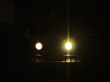 After I
converted the left side (from the driver's perspective) I ran a
test. This photo doesn't really show the difference in brightness
as the left headlight has saturated the camera. When I blocked each
headlight with my finger, then the difference really showed up. ALL
of the light cast forward was coming from the upgraded LED. When it
was blocked, the area in front of the Railtruck was completely
dark. Also, not reproduced by the photo very well was the color.
The upgraded headlight was much less yellow than the stock one.
After I
converted the left side (from the driver's perspective) I ran a
test. This photo doesn't really show the difference in brightness
as the left headlight has saturated the camera. When I blocked each
headlight with my finger, then the difference really showed up. ALL
of the light cast forward was coming from the upgraded LED. When it
was blocked, the area in front of the Railtruck was completely
dark. Also, not reproduced by the photo very well was the color.
The upgraded headlight was much less yellow than the stock one.
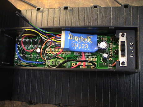 I originally elected to install a Digitrax DH123D decoder in the
Railtruck. The installation is straight forward by following the
DCC diagram provided by Bachmann. The only twist is that when the
slide switch is set to position "3" (G gauge), the truck runs
backwards. The easiest fix is to flip the switch to position "2".
Then the Railtruck direction matches the throttle. Since the
forward and reverse headlight function wires from the decoder are
in parallel, the lights are on in both directions.
I originally elected to install a Digitrax DH123D decoder in the
Railtruck. The installation is straight forward by following the
DCC diagram provided by Bachmann. The only twist is that when the
slide switch is set to position "3" (G gauge), the truck runs
backwards. The easiest fix is to flip the switch to position "2".
Then the Railtruck direction matches the throttle. Since the
forward and reverse headlight function wires from the decoder are
in parallel, the lights are on in both directions.
The DH123 is an HO sized decoder but it runs fine on 22 volts as well as 16 volts. The current drawn by the Railtruck is only about 300 mA so this 1.5 amp decoder has no trouble with it. However, the DH123 doesn't have sound.
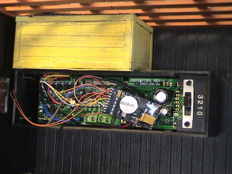 The ESU LokSound V3.5 decoder
DOES have sound, and very good sound at that for about $110 and
another $8 for a better speaker than the dinky one that comes with it. It fits in the toolbox nicely so I
guess that the toolbox is going to stay. This is the same decoder
that I put in a Bachmann
Davenport. There are samples of the sound and performance of
this decoder on the LokSound page.
The ESU LokSound V3.5 decoder
DOES have sound, and very good sound at that for about $110 and
another $8 for a better speaker than the dinky one that comes with it. It fits in the toolbox nicely so I
guess that the toolbox is going to stay. This is the same decoder
that I put in a Bachmann
Davenport. There are samples of the sound and performance of
this decoder on the LokSound page.
However, as expected, the excellent BEMF capability of this decoder did nothing to improve the tendency of this loco to surge.
 The LokSound V3.5 is an HO sized decoder and it uses an odd
100Ω speaker. This is the largest one that ESU provides. It is
40 mm in diameter. It just so happened that the crate that I had
built before for the oval speaker was just high enough to hold this
speaker when I put some extra plastic sheet across the front to
seal the enclosure.
The LokSound V3.5 is an HO sized decoder and it uses an odd
100Ω speaker. This is the largest one that ESU provides. It is
40 mm in diameter. It just so happened that the crate that I had
built before for the oval speaker was just high enough to hold this
speaker when I put some extra plastic sheet across the front to
seal the enclosure.
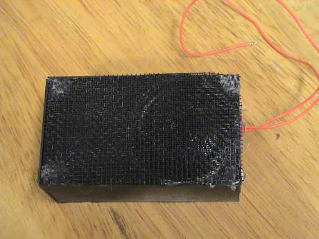 The
speaker points out through the stake side of the Railtruck and is
better concealed with a double layer of black plastic window screen
glued over it.
The
speaker points out through the stake side of the Railtruck and is
better concealed with a double layer of black plastic window screen
glued over it.
[ Top ] [ Home ] [ Up ] [ Previous Page ] [ Next Page ]
This page has been accessed times since 2 Jun 08.
© 2009-2010 George Schreyer
Created 2 Jun 08
Last Updated September 10, 2010