 24 Feb 09 31 Jul 11
 17 Jan 09 20 May 09
[ Home ] [ Up ] [ Previous Page ] [ Next Page ]
24 Feb 09 31 Jul 11 17 Jan 09 20 May 09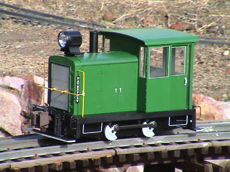 The Bachmann Davenport is a model
of a gas mechanical switcher engine. These engines were typically
too small for use on a Class 1 railroad, but they found lots of use
in industrial activities, mining and logging for switching one or
two cars at a time on private property.
The Bachmann Davenport is a model
of a gas mechanical switcher engine. These engines were typically
too small for use on a Class 1 railroad, but they found lots of use
in industrial activities, mining and logging for switching one or
two cars at a time on private property.
This model is 1:20.3 scale and represents a 1940's vintage narrow gauge loco. The gasoline engine was connected via a conventional geared transmission or hydraulic torque converter to one axle. The other axle is driven via the siderods.
The loco runs very smoothly and quietly. Even though there are only 4 wheels contacting the track, it's power pickup is extremely good, so good that I am suspicious about what is going on. It didn't sputter at all when running on track that had just been rained on and hadn't been cleaned at all in over a week. It's performance can be seen in this short h.264 video. However, note the dismal performance of the headlight. During more testing I found one spot where it stalled. It ran over a freshly fallen ivy leaf and all four wheels were on top of the leaf, but it hadn't derailed.
Overall, I am extremely pleased with the performance and construction of this little loco. Much of the structure and detail of the model is die cast metal so even though the loco is small, it is fairly heavy and pulls well for it's size.
The current draw is reasonable too, but it might be a little much for the recommended HO sized DCC decoder.
| Condition | DC Current (amps) | Notes |
|---|---|---|
| Running light | 0.5 | Average, varies from 0.4 to 0.6 |
| Pulling, no slip | 0.9 | 5 heavy cars on a 1.6% grade |
| Pulling, slipping | 1 | 6 heavy cars on a 1.6% grade |
| Full Slip | 1.4 | Restrained from movement via the rear coupler |
| Hard Stall | 3 | Pressed down onto the track until motor stalled |
However, there is one performance problem. The Davenport surges on steeper grades. I didn't notice any surging on the 1.6% grades of the GIRR, but on the 4.2% grades of the GIRR Mtn Div, the surging is pretty severe as can be seen in this h.264 video clip. The drive train is pretty tight, already, there doesn't seem to be much that can be done about this except to put up with it.
However, when the gearbox is heavily greased, which actually increases the drag in the gearbox, the surging is materially improved as seen in this before and after video clip.
While greasing did improve the surging, it didn't fix it. I have installed a BEMF DCC decoder (ESU LokSound V3.5) into the Davenport and I was told that a BEMF decoder would stop a loco from surging. I didn't believe it because the surging is NOT caused by stalling of the motor so that BEMF (which tends to keep the motor running) shouldn't help. It didn't as can be seen in this h.264 video. It still surges pretty much the same as before. Any improvement can be attributed to the gearbox greasing and not the BEMF decoder.
The Davenport seems to have more difficulty stalling on the frogs of Aristocraft tight radius turnouts than it had on LGB 1600 turnouts. I am not sure exactly what the issue is.
Just for grins, I put the Davenport on the trolly line which has 2 foot diameter loops. It ran fine. It could easily handle some very tight mountain track.
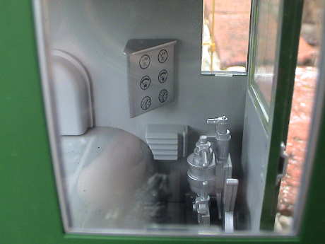 The Davenport has a
fairly well detailed cab. There is a panel with gauges and meters,
a control stand and a swiveling engineer's seat. The motor is
actually in the cab so that it consumes much of the floor.
The Davenport has a
fairly well detailed cab. There is a panel with gauges and meters,
a control stand and a swiveling engineer's seat. The motor is
actually in the cab so that it consumes much of the floor.
This is a 1:20.3 scale loco so it will take a fairly large figure for an engineer. However there is little room for his feet and the cab is so open that the standard hack of cutting the figure off at the knees would be too visible. But the Davenport looks kind of funny running around with an obviously empty cab.
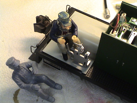 I found two
figures in my junk box that were candidates. The larger unpainted
one is about the right size but he is just too big to fit. I'd have
to hack off the right side of his whole leg and arm. The leg
wouldn't be too visible, but the arm would be right by the windows,
unacceptable.
I found two
figures in my junk box that were candidates. The larger unpainted
one is about the right size but he is just too big to fit. I'd have
to hack off the right side of his whole leg and arm. The leg
wouldn't be too visible, but the arm would be right by the windows,
unacceptable.
The smaller painted one actually fit pretty well once I cocked
him to the side a bit. His swivel chair isn't in line with the
brake stand anyway so this the only way that he would fit. I only
had to grind off part of his coat tail where it interfered with the
motor compartment. With a couple of dabs of hot glue on his shins,
he is pretty secure.
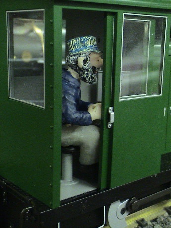 It's a tight fit,
but the door will still close. I wanted him looking more directly
forward, but I elected not to cut off and rotate his head.
It's a tight fit,
but the door will still close. I wanted him looking more directly
forward, but I elected not to cut off and rotate his head.
 The main PWB and some
switches are under the hood which can simply be pulled off by using
the headlight bracket.
The main PWB and some
switches are under the hood which can simply be pulled off by using
the headlight bracket.
The switch to the front is the smoke switch. The one behind it is the motor polarity switch. This switch has a center off position as well. The smoke unit is a standard Bachmann item. It works as well as the rest of them, making a reasonable stream of smoke. It can be filled via the stack but the hood has to come off the turn it off or on. With the way that it is wired though, it would be trivial to control the smoke unit via a DCC function.
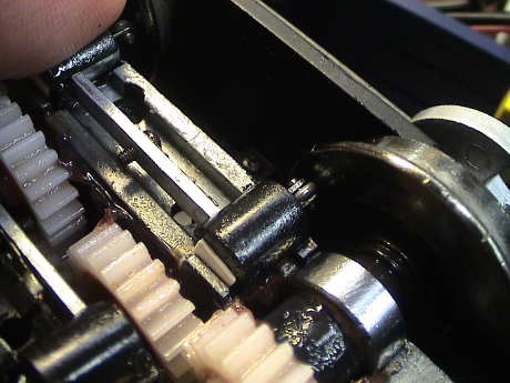
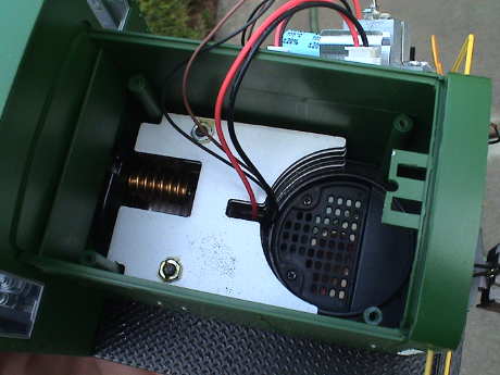 With the PWB removed,
(just 4 screws), the worm from the motor can be seen in a notch in
a weight. There is also a spot for a speaker. It appears to be
arranged for an approximately 1.6" (40 mm) round speaker.
With the PWB removed,
(just 4 screws), the worm from the motor can be seen in a notch in
a weight. There is also a spot for a speaker. It appears to be
arranged for an approximately 1.6" (40 mm) round speaker.
The motor comes up on two wires, the track contacts on two others and the headlight connects from the top with two more wires. All the rest of the wiring is on the PWB which wouldn't be needed for a battery/RC conversion anyway. The hood is just wide enough to take AA batteries laying crosswise and even more room could be made by removing part of the weight which could still leave room for a speaker.
 Underneath, the
roller contacts for power pickup can be seen. These work really
well, but will probably need consistent lubrication to allow a good
service life.
Underneath, the
roller contacts for power pickup can be seen. These work really
well, but will probably need consistent lubrication to allow a good
service life.
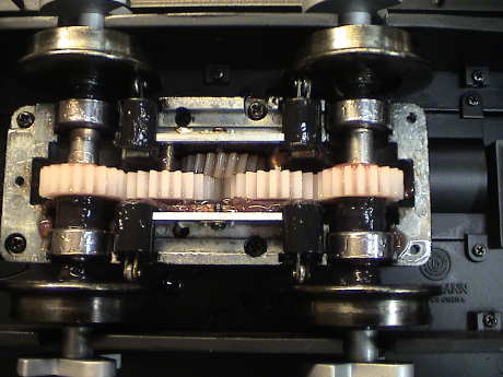 The brick is a heavy
diecast assembly. The main drive gear drives a chain of spur gears
that drive the two axles. The axles are set in ball bearings. The
siderods are for decoration only, they do not contribute to the
drive chain. The drive chain is fairly tight without serious
backlash.
The brick is a heavy
diecast assembly. The main drive gear drives a chain of spur gears
that drive the two axles. The axles are set in ball bearings. The
siderods are for decoration only, they do not contribute to the
drive chain. The drive chain is fairly tight without serious
backlash.
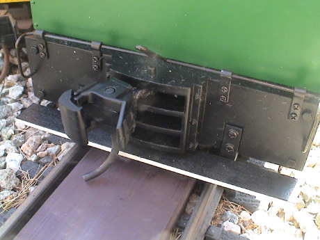
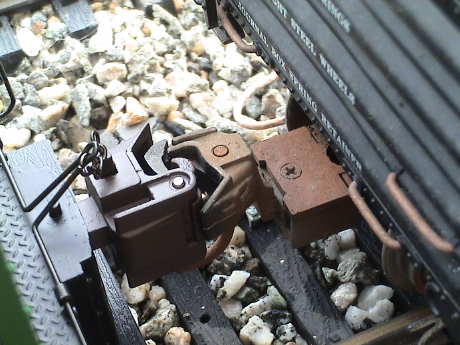 The Davenport
comes equipped with diecast knuckle couplers with operating cut
levers, a nice touch. There is also another set of off set knuckle
couplers in the box if you want to mount them lower.
The Davenport
comes equipped with diecast knuckle couplers with operating cut
levers, a nice touch. There is also another set of off set knuckle
couplers in the box if you want to mount them lower.
These are the FIRST Bachmann couplers that I have seen that mate properly with Kadee couplers. I've seen several write ups on the internet about changing the Davenport's couplers to Kadee couplers, but it does not appear to be necessary.
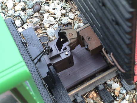 Not only do the
Davenport's couplers mate with Kadee couplers, they actually work
with delayed uncoupling as well. There might be some trouble if
there is slack in the couplers while running over a track magnet,
but it didn't appear to be a serious difficulty.
Not only do the
Davenport's couplers mate with Kadee couplers, they actually work
with delayed uncoupling as well. There might be some trouble if
there is slack in the couplers while running over a track magnet,
but it didn't appear to be a serious difficulty.
 The Bachmann knuckle
mates with an LGB knuckle as well. The coupling is solid and it
takes about the same bump to close both knuckles as it does with a
pair of LGB knuckles. For my purposes, it looks like a coupler
conversion is not necessary.
The Bachmann knuckle
mates with an LGB knuckle as well. The coupling is solid and it
takes about the same bump to close both knuckles as it does with a
pair of LGB knuckles. For my purposes, it looks like a coupler
conversion is not necessary.
After using the Davenport with the stock coupler for awhile, it became clear that the delayed uncoupling feature of the Kadee coupler indeed doesn't work every time with the stock Bachmann coupler. Although coupling is easy and reliable, uncoupling with a magnet uncoupler is not reliable. It will work with some cars and not others depending mostly on the characteristics of the other car.
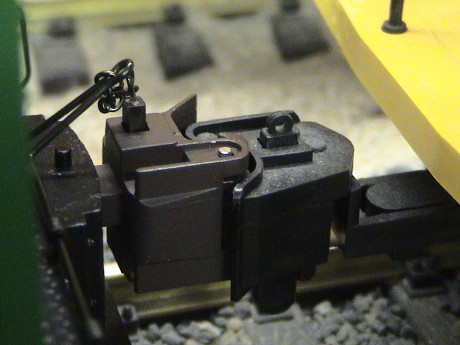
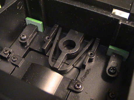
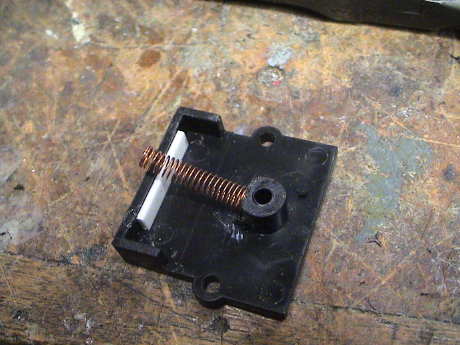
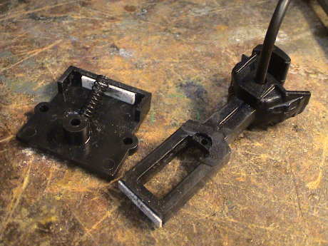
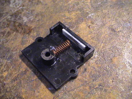
 This is the
stock Bachmann coupler box. It attaches with just two screws and
pulls off easily.
This is the
stock Bachmann coupler box. It attaches with just two screws and
pulls off easily.
 The Bachmann
coupler uses a plastic centering spring similar in design to the
most common Kadee HO configuration.
The Bachmann
coupler uses a plastic centering spring similar in design to the
most common Kadee HO configuration.
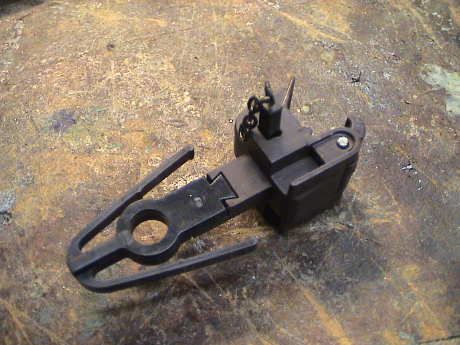 The stock
Bachmann coupler is cast metal. The spring is plastic. They attach
together with a single screw and a dovetail locking joint.
The stock
Bachmann coupler is cast metal. The spring is plastic. They attach
together with a single screw and a dovetail locking joint.
It turns out that the coupler slot in the loco body is at exactly the right height above the rails and has exactly right opening to take a Kadee centerset coupler so a version of the centerset coupler was clearly the right starting point. I happened to have two versions, the one that comes with the Kadee #820 kit, and the Kadee 1850 from a Kadee #835 kit. Since it wasn't clear what method would work the best, I elected to try it both ways. Neither way would require any modification to the loco proper. Using the 1850 required reuse of the stock Bachmann spring. Using the 820 would require slight modifications to the draft gear cover. I figured that should there be a problem with the installation and I had to revert, there was a second set of centering springs that came with the loco and the modifications to the draft gear box cover would be reversible.
 I did
both versions in parallel, but the one that worked out first was
the one using the Kadee 1850. This required the most modifications
to the coupler itself, but when that was done, it worked almost
right away.
I did
both versions in parallel, but the one that worked out first was
the one using the Kadee 1850. This required the most modifications
to the coupler itself, but when that was done, it worked almost
right away.
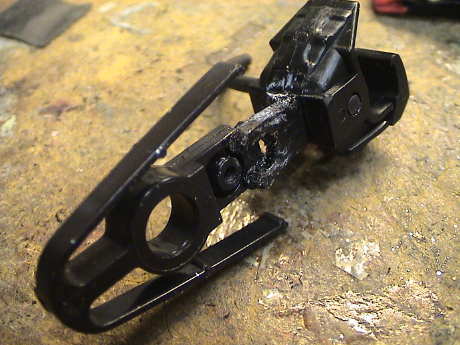
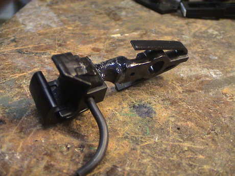
It took me a little cutting and trying to figure out exactly what I needed to do so that the modification looks a little ugly. If I did this again, it would be neater. In this photo, the coupler tang has been ground down to half height to more or less match the configuration of the original coupler. However, it is too short to reach to the original mounting hole and the original screw wouldn't work anyway because the existing hole in the coupler is too large.
In this photo, the hacked 1850 is attached to the stock spring with a little Zap-A-Gap CA.
 The Zap-A-Gap was there only to hold it together while a
structural epoxy set up. The epoxy fills around all the bumps and
lumps on the coupler and spring and makes a strong enough
joint.
The Zap-A-Gap was there only to hold it together while a
structural epoxy set up. The epoxy fills around all the bumps and
lumps on the coupler and spring and makes a strong enough
joint.
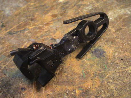
Note that the Bachmann springs have been trimmed about 1/8". This was necessary because the spring was a little too stiff and prevented the coupler from kicking sideways over a magnet.
 After the epoxy had set, it was filed so that there was no epoxy
on the surface of the spring facing downward against the coupler
pocket. Epoxy doesn't slide on plastic well, but plastic on plastic
does. When the coupler is hovering over a magnet, it is pulled down
and the extra friction of an epoxy to plastic interface would
prevent the coupler from kicking sideways to allow delayed
uncoupling.
After the epoxy had set, it was filed so that there was no epoxy
on the surface of the spring facing downward against the coupler
pocket. Epoxy doesn't slide on plastic well, but plastic on plastic
does. When the coupler is hovering over a magnet, it is pulled down
and the extra friction of an epoxy to plastic interface would
prevent the coupler from kicking sideways to allow delayed
uncoupling.
 When
the coupler was reinstalled, the epoxy filed and the spring
adjusted, the coupler opens reliably and moves sideways a bit to
facilitate the delayed uncoupling feature of the Kadee coupler.
When
the coupler was reinstalled, the epoxy filed and the spring
adjusted, the coupler opens reliably and moves sideways a bit to
facilitate the delayed uncoupling feature of the Kadee coupler.
This end was done. The other end initially fit up better, but I had considerable problems with getting the Kadee centering spring to work properly in the Bachmann draft gear box.
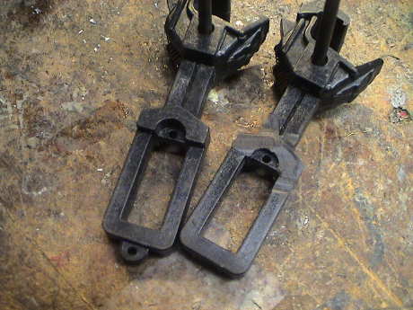 The
centerset straight shank coupler from the #820 kit required some
modifications to fit in the Bachmann draft gear. First, there is a
ridge, seen on the unmodified on on the left, that had to be ground
off to make it fit in the coupler slot. The the little tab and the
end needed to be cut off to make enough room.
The
centerset straight shank coupler from the #820 kit required some
modifications to fit in the Bachmann draft gear. First, there is a
ridge, seen on the unmodified on on the left, that had to be ground
off to make it fit in the coupler slot. The the little tab and the
end needed to be cut off to make enough room.
 Getting the thing
assembled was going to be a problem as the coupler had to go in
first, then the box would fit over it. However, engaging the spring
was going to be tricky. However, I found that if I used a longer
spring and attached the end of the spring to the box cover with a
little CA, it would hang over the end and it made catching the
spring in the shank quite easy. Unfortunately, the spring was too
long and was nearly fully collapsed as installed.
Getting the thing
assembled was going to be a problem as the coupler had to go in
first, then the box would fit over it. However, engaging the spring
was going to be tricky. However, I found that if I used a longer
spring and attached the end of the spring to the box cover with a
little CA, it would hang over the end and it made catching the
spring in the shank quite easy. Unfortunately, the spring was too
long and was nearly fully collapsed as installed.
Further, the coupler sat too far inward and the coupler would drag on the end of the pocket. The white styrene shim is there to push the coupler outward just a little. The flat part of the rear of the coupler rides on this shim and centers the coupler, but it also prevents the coupler from un-centering easily under the influence of the uncoupler magnet.
 While playing
with the profile of the rear of the shank, I rounded the corners,
but this actually made it worse. I ground off a little more and
then shimmed the end with another piece of 0.020" styrene. The very
ends of this piece can bend a little over the rounding on the end
of the shank and provide an improvement in the centering action.
This view also has a different spring, an Aristo freight truck
spring. This one turned out to be too stiff.
While playing
with the profile of the rear of the shank, I rounded the corners,
but this actually made it worse. I ground off a little more and
then shimmed the end with another piece of 0.020" styrene. The very
ends of this piece can bend a little over the rounding on the end
of the shank and provide an improvement in the centering action.
This view also has a different spring, an Aristo freight truck
spring. This one turned out to be too stiff.
 In this
photo, I've substituted a short Kadee spring. I don't recall
exactly what spring was originally in the Kadee 820 kit as it's
pieces had been distributed in a parts box with all the other
hundreds of spare Kadee parts that I had. This spring turned out to
be a little short and too weak, but another piece of 40 mil shim
inside the end of the shank shortened up the span enough to make it
work well enough.
In this
photo, I've substituted a short Kadee spring. I don't recall
exactly what spring was originally in the Kadee 820 kit as it's
pieces had been distributed in a parts box with all the other
hundreds of spare Kadee parts that I had. This spring turned out to
be a little short and too weak, but another piece of 40 mil shim
inside the end of the shank shortened up the span enough to make it
work well enough.
Since this spring didn't stick out of the box enough to engage the shank, I reattached it at an angle so that the end stuck out far enough so that it would catch the shank during assembly.
This was about the most fiddling around that I have ever had to do to get a Kadee to fit and work. If I had to do it again, I'd use the 1850 coupler method as it seemed to re-center with more authority.
Of course, only after I was finished did I think to look on the internet to see how other might have done this modification. Search the MLS Forums for "Davenport Kadee" to find some alternate methods, one of them pretty close to the method that I used for the 1850 version.
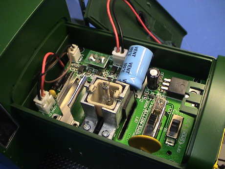
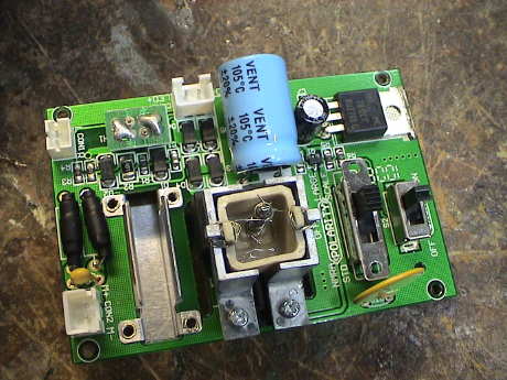 The PWB in the Davenport
is a pretty simple board. It contains connectors for the track
power contacts, the motor and the headlight. There is a 12 volt
regulator that runs the smoke unit, but nothing else. There are RFI
filter chokes in series with both motor leads and a small capacitor
across the motor leads. The yellow part in the lower right is a
polyswitch.
The PWB in the Davenport
is a pretty simple board. It contains connectors for the track
power contacts, the motor and the headlight. There is a 12 volt
regulator that runs the smoke unit, but nothing else. There are RFI
filter chokes in series with both motor leads and a small capacitor
across the motor leads. The yellow part in the lower right is a
polyswitch.
There is an NMRA standard 8 pin DCC socket with it's jumper plug
installed and a metal pocket in which to stash a decoder.
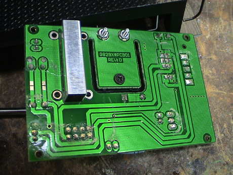 There are no parts on
the bottom of the board but this is where most of the track power
and motor traces are.
There are no parts on
the bottom of the board but this is where most of the track power
and motor traces are.
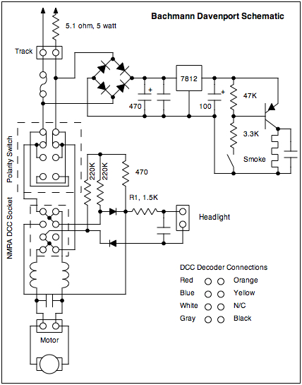
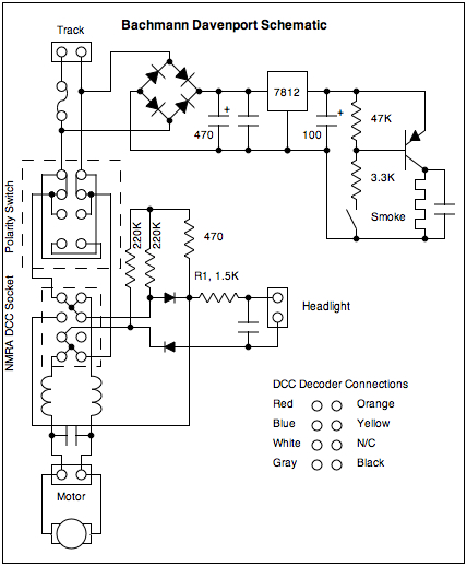 The schematic
of the Davenport is pretty straightforward. Track power is
delivered to the regulator for the smoke circuit and to the
reversing switch. From the reversing switch it goes to the DCC
plug. The jumpers are shown which then route power to the motors.
Track power is also delivered to the headlight circuit. The 1.5K
resistor sets the intensity of the headlight. There are three
resistors in the headlight circuit (2 ea 220K and one 470) that I
don't see the need for but they are there anyway.
The schematic
of the Davenport is pretty straightforward. Track power is
delivered to the regulator for the smoke circuit and to the
reversing switch. From the reversing switch it goes to the DCC
plug. The jumpers are shown which then route power to the motors.
Track power is also delivered to the headlight circuit. The 1.5K
resistor sets the intensity of the headlight. There are three
resistors in the headlight circuit (2 ea 220K and one 470) that I
don't see the need for but they are there anyway.
The schematic is drawn showing the jumper plug installed in an X-ray view (looking through the board). A DCC decoder connection diagram is also shown with the wire colors typically associated with a decoder. The 8 pin NMRA socket is designed so that if it is plugged in backwards, which is possible, no damage will occur but the engine will run backwards under DCC and the headlights won't work.
The way that the smoke circuit is wired, a DCC function could be wired to the smoke switch and be used to activate the smoke circuit without having to open the hood. In either case, one has to be careful to turn the smoke unit off when it runs dry or risk burning it up.
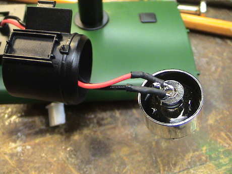 The Davenport has
a really wimpy orange LED housed within a huge headlight enclosure.
The size of the headlight assembly looks odd for such a small loco.
Not only does the headlight not cast any sort of a beam, it was
hardly visible in daylight. This had to get fixed.
The Davenport has
a really wimpy orange LED housed within a huge headlight enclosure.
The size of the headlight assembly looks odd for such a small loco.
Not only does the headlight not cast any sort of a beam, it was
hardly visible in daylight. This had to get fixed.
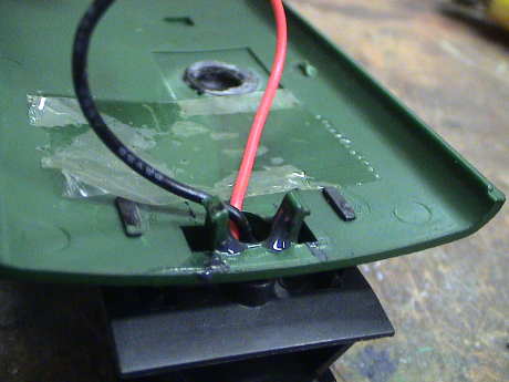
The headlight is pretty easy to get apart. It snaps off it's mounting bracket. There is a tab on the back of the reflector (right between the LED leads) that can be pressed with a small screwdriver inserted through the wire entry hole. Pressing on this tab will force the reflector out of the assembly and the lens will then pop out. Once the reflector is pulled out, the headlight is easy to replace with a more suitable white or warm white 5 mm LED. The red wire is the positive wire, it connects to the LED lead that goes to the smaller electrode inside the LED package.
The headlight lens is metalized and the hole that the leads come through is pretty small. Bachmann didn't insulate the leads all the way back to the LED housing leaving the possibility of a short. Nothing bad would happen except that the headlight would not work. When I reinstalled the new LED, I pushed shrink tube right back to the base of the LED. Two pieces of shrunk 1/16" shrink tube will fit back through the hole, but it is tight.
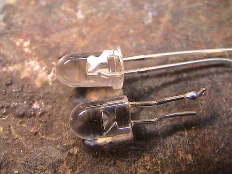 There is one complication
though. The stock Bachmann LED does not have the flange at the back
of the lens. The flange must be clipped and filed off for a new LED
to fit back into the reflector.
There is one complication
though. The stock Bachmann LED does not have the flange at the back
of the lens. The flange must be clipped and filed off for a new LED
to fit back into the reflector.
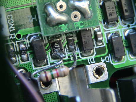 The replaced
LED is MUCH brighter than the stock one, but the stock Bachmann
circuit board sets the current lower than the LED can tolerate. The
1.5K resistor, R1, is the primary current source. It sets the LED
current to 10 mA. Paralleling it with another 1.5K resistor
increases the LED current to 20 mA and roughly doubles the
headlight intensity. The easiest spot to connect the additional
resistor is shown in the photo. You'll need a fine pencil tip
soldering iron and some fine solder to make these joints. R1 is a
really small surface mount part, you have to work really quickly or
the whole resistor will unsolder itself.
The replaced
LED is MUCH brighter than the stock one, but the stock Bachmann
circuit board sets the current lower than the LED can tolerate. The
1.5K resistor, R1, is the primary current source. It sets the LED
current to 10 mA. Paralleling it with another 1.5K resistor
increases the LED current to 20 mA and roughly doubles the
headlight intensity. The easiest spot to connect the additional
resistor is shown in the photo. You'll need a fine pencil tip
soldering iron and some fine solder to make these joints. R1 is a
really small surface mount part, you have to work really quickly or
the whole resistor will unsolder itself.
I tested the original orange LED at 10 mA and another warm white LED at 20 mA to see what change in intensity that I actually got after changing the LED and changing the current. I used my Pentax SpotMeter to measure the intensity. The stock LED registered a peak of EV10. The warm white LED registered EV15. One EV is a change in intensity of a factor of two. Therefore a 5 EV change is 25 or 32 times. This is a big difference. 24 of that change is due to the LED itself. Only the last factor of 2 is due to current.
The Davenport is configured to accept a DCC decoder, but Bachmann didn't provide a recommendation as to what type to use. Many HO decoders are not rated to handle the 1.5 amps that this loco draws at full slip. I recently burned up a DH123 in a loco that draws about the same current as the Davenport so I am going to look around to see what other folks have successfully used in the Davenport.
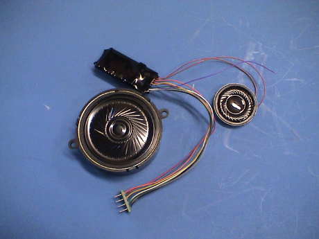 The only DCC
installation that I could find in the Davenport successfully used
the Lenz Gold and Silver series decoders, but these don't have
sound. I elected to use a decoder that was new to me, the ESU
LokSound V3.5. These systems are designed in Germany and
manufactured in the Czech Republic. This one is an HO sized decoder
that has integrated sound with a Goose sound file. It comes with a
dinky speaker but I purchased a 40 mm version that fits perfectly
in the Davenport. However, these speakers are 100Ω units and
I was suspicious that the sound volume would not be high enough for
outdoors. It turns out to be better than the other HO sound
decoders that I have used, the Soundtraxx DSX and Digitrax SFX0416,
but it is still not nearly as loud as an average large scale sound
system. You can find more information on the performance of this
decoder at my LokSound
Tips page.
The only DCC
installation that I could find in the Davenport successfully used
the Lenz Gold and Silver series decoders, but these don't have
sound. I elected to use a decoder that was new to me, the ESU
LokSound V3.5. These systems are designed in Germany and
manufactured in the Czech Republic. This one is an HO sized decoder
that has integrated sound with a Goose sound file. It comes with a
dinky speaker but I purchased a 40 mm version that fits perfectly
in the Davenport. However, these speakers are 100Ω units and
I was suspicious that the sound volume would not be high enough for
outdoors. It turns out to be better than the other HO sound
decoders that I have used, the Soundtraxx DSX and Digitrax SFX0416,
but it is still not nearly as loud as an average large scale sound
system. You can find more information on the performance of this
decoder at my LokSound
Tips page.
 This is the LokSound
decoder installed in the Davenport. The decoder comes with an NMRA
8 pin plug that fits properly in the Davenport DCC socket. This
connects all the basic functions, motor and headlights. The decoder
fits nicely in the metal pocket provided by Bachmann. There is only
one additional function wire on the LokSound decoder, the violet
one for AUX2. This can either be insulated and not used or
connected to control the smoke.
This is the LokSound
decoder installed in the Davenport. The decoder comes with an NMRA
8 pin plug that fits properly in the Davenport DCC socket. This
connects all the basic functions, motor and headlights. The decoder
fits nicely in the metal pocket provided by Bachmann. There is only
one additional function wire on the LokSound decoder, the violet
one for AUX2. This can either be insulated and not used or
connected to control the smoke.
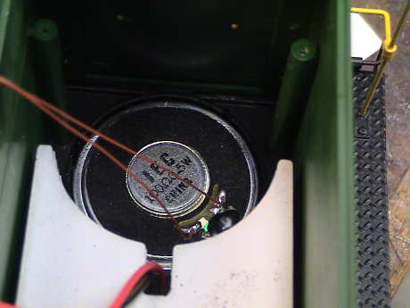 The LokSound special
speaker fits in the mount provided by Bachmann. However, there is
no clamping mechanism so I held it in with a couple of drops of
Zap-A-Gap CA. The brown speaker wires that come on the decoder are
just long enough to reach the speaker. The speaker actually comes
with a plastic rear enclosure, but it increases the diameter
slightly and then the speaker won't fit well. The enclosure really
isn't necessary because the hood provides a good enclosure.
The LokSound special
speaker fits in the mount provided by Bachmann. However, there is
no clamping mechanism so I held it in with a couple of drops of
Zap-A-Gap CA. The brown speaker wires that come on the decoder are
just long enough to reach the speaker. The speaker actually comes
with a plastic rear enclosure, but it increases the diameter
slightly and then the speaker won't fit well. The enclosure really
isn't necessary because the hood provides a good enclosure.
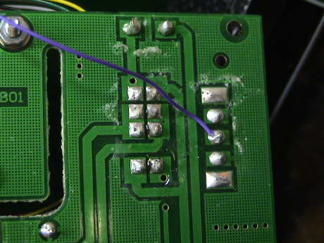 I used the AUX2
function (violet) wire to control the smoke so that I don't have to
pop the hood to turn the smoke on and off. Bachmann provided a
circuit to control the smoke unit that is apparently designed to
accept a DCC function. I just soldered the wire to the contact on
the switch to pull down 3.3K resistor at the base of the smoke control transistor and
activate the smoke.
I used the AUX2
function (violet) wire to control the smoke so that I don't have to
pop the hood to turn the smoke on and off. Bachmann provided a
circuit to control the smoke unit that is apparently designed to
accept a DCC function. I just soldered the wire to the contact on
the switch to pull down 3.3K resistor at the base of the smoke control transistor and
activate the smoke.
I did have issues with ESU decoder both with sound volume and with power pickup interruptions, especially on insulated turnout frogs. The decoder also interacted badly when the power pickups degraded as described below but that was easy to fix and then the decoder again had problems on on turnout frogs. The details of the ESU specific issues are on my LokSound Tips page.
On May 4, 2009, I was running the Davenport pulling an Aristo Track cleaning car. After about half an hour, the sound stopped. After I set the speed to zero, it never ran again. I quickly pulled the decoder and found that it was pretty warm and the shrink wrap had melted back over a large area. The decoder was toast.
LokSound decoders have a 2 year warranty so I sent it back. About two weeks later a new one appeared in the mail as a replacement. It installed without difficulty. The 8 pin plug was of a little different design. It had a stress relief for the wires. An 8 pin decoder can be plugged in either way, but one way the headlight won't work. Of course I got it backwards the first time. The correct orientation is for the stress relief to be on the fireman's side.
I had the program for the decoder stored in JMRI DecoderPro so I just reloaded my programming from the saved data and it was good to go.
Note to self: don't load this loco up too heavily.
After a period of time, I noticed that the sound would often cut out with the loco just standing and idling on the track. If I pinched the decoder in my fingers, it was pretty warm, and in particular spots. After a few seconds, it would come on again. This told me that just the audio amplifier running by itself without any heating from the motor driver was enough to make it run hot enough to shut down. Heat sinking it with my fingers would cause it to restart.
I ran a test of the loco on my test track. If I let it sit and idle at 22 volts on the track, it would sometimes shut down, especially if I gave it a little help with some hot air from a hot air gun. At 18 volts on the test track, it would not shut down, even with some added hot air. This was enough to convince me that the ESU LokSound V3.5 decoder doesn't like 22 volts and running at full volume. When the motor is running, the motor driver adds enough heat at 22 volts to cause the sound to shut off after 10 or 15 minutes of running light. At 18 volts, it doesn't shut down.
There were two ways around this problem. I could kludge in a fan to keep the decoder cooler or I could reduce the voltage. The obviously better approach is to reduce the voltage for this loco alone by adding a resistor in series with a track feed. This would cause the voltage at the decoder to decrease as the load on the decoder increased, helping it keep it's temperature under control. Since I run this loco pretty slowly anyway and it doesn't have enough weight to pull a heavy load anyway, loss of voltage isn't a real big problem.
 The best place to install
the resistor is directly in series with the decoder, but I choose
to install it in a track lead instead. There were a few reasons for
this. The decoder wires are pretty fine and the resistor is pretty
big. I didn't want to add stress to the decoder leads. Also, the
smoke unit will make heat inside the hood when it runs. Since the
smoke unit current will also flow in the resistor, turning the
smoke on will drop the voltage a little more allowing the decoder
to live in a warmer environment.
The best place to install
the resistor is directly in series with the decoder, but I choose
to install it in a track lead instead. There were a few reasons for
this. The decoder wires are pretty fine and the resistor is pretty
big. I didn't want to add stress to the decoder leads. Also, the
smoke unit will make heat inside the hood when it runs. Since the
smoke unit current will also flow in the resistor, turning the
smoke on will drop the voltage a little more allowing the decoder
to live in a warmer environment.
The resistor value was picked to provide some voltage drop at idle with full volume and not too much at full load. I initially used 10 ohms, but it was too much. I settled on 5.1 ohms. 5 watts which is a good dissipation value because the dissipation of the resistor will be just shy of 4 watts at the worst loads.
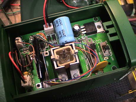
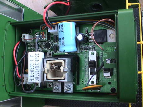 The resistor I
used is a 5 watt sandstone type. It can be installed in either the
black or brown leads leading to the power input connector on the
PWB. When the loco is pulling a heavy load such as an Aristo track
cleaning car, the loco does slow down and the resistor gets hot,
but this means that the decoder ISN'T getting as hot. The resistor
is clipped in the metal pocket that was used for the decoder. The
decoder itself it tucked between the PWB and the front of the loco
to get it far away from other sources of heat.
The resistor I
used is a 5 watt sandstone type. It can be installed in either the
black or brown leads leading to the power input connector on the
PWB. When the loco is pulling a heavy load such as an Aristo track
cleaning car, the loco does slow down and the resistor gets hot,
but this means that the decoder ISN'T getting as hot. The resistor
is clipped in the metal pocket that was used for the decoder. The
decoder itself it tucked between the PWB and the front of the loco
to get it far away from other sources of heat.
While running pulling my Aristo track cleaning car AND pushing my camera car, it still tripped off the sound. When only one car is connected, it runs for longer but after awhile, the sound will still trip. Although the decoder itself still gets pretty hot, at least it doesn't burn up. When I reduce the track voltage to 16 volts, it will run continuously with either car. I haven't tried that with both of them. With the track cleaning car in tow and 16 volts on the track, the hottest spot on the decoder is about 175°F (80°C) and the resistor is running 220°F (105°C). This is pretty hot.
It looks like this decoder, as good as it sounds, is really limited in the service it can provide on a large scale DCC layout. It has never given me problems in the Bachmann Railtruck but there it runs without a load and on 18 volts.
I had an open house yesterday and I ran the Davenport pushing the video car for maybe an hour. It started to show the signs of thermal trouble again, but not as badly as in the past. The sound would shut down at the slightest power interruption and restart again when the decoder was "rebooted" by doing a track power cycle. I removed the 5.1Ω sandstone resistor and substituted a 10Ω resistor. It still ran fine light.
This morning, I ran it under the same load for well more than an hour and it didn't seem to be having any problems. It still pushed the car at acceptable speeds.
The issue is that the decoder will run at up to 27 volts and it will drive a motor at 1.1 amps, but just not at the same time. It would appear that it will handle a 700 mA load at 15 volts. The sound part seems to have issues first. With the heat produced by the motor driver added to the heat produced by a voltage regulator driving the sound system, the sound regulator appears to shut down when the input voltage is too high and the decoder is hot anyway.
A LokSound Select would be a better choice in this application than the LokSound v3.5. It's sound system uses a Class D amp and is not subject to regulator overheating.
If something is too good to be true, it probably is. The excellent power pickup of the Davenport degraded over time due to two different problems, but both problems turned out to be fixable.
First, a non-conductive oil (LGB 50019) that I put on the contacts was causing serious problems. The resistance of the contacts increased significantly and the loco started to behave really badly. This interacted with the ESU decoder's tendency to shutdown and restart, but the loco still ran badly on DC. I cleaned the oil off the backs of the wheels with a paper towel and dribbled some isopropyl alcohol onto the contacts to dissolve the oil that was on them and then cleaned the wheels again. This problem went away but another one surfaced.
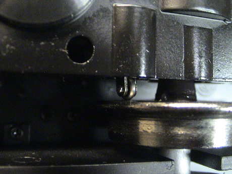
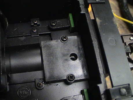
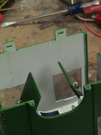
 As I was playing with
the Kadee contact brush on the bench I noticed that if I used the
brush to push the axles to the engineer's side, the loco would stop
dead. A quick visual inspection revealed that the contacts on the
engineer's side were not making contact with the wheels at the
extreme of the axle movement. The gap was only a few mils, but ANY
gap is enough. This had to get fixed. Removal of the engine cover
revealed that the contact assemblies could be pushed over a little.
A piece of 20 mil styrene was just right. It fits behind the
contact assembly and biases the contact toward the engineer's side.
This fixed the axle slop problem completely, reliable contact was
regained at all axle positions.
As I was playing with
the Kadee contact brush on the bench I noticed that if I used the
brush to push the axles to the engineer's side, the loco would stop
dead. A quick visual inspection revealed that the contacts on the
engineer's side were not making contact with the wheels at the
extreme of the axle movement. The gap was only a few mils, but ANY
gap is enough. This had to get fixed. Removal of the engine cover
revealed that the contact assemblies could be pushed over a little.
A piece of 20 mil styrene was just right. It fits behind the
contact assembly and biases the contact toward the engineer's side.
This fixed the axle slop problem completely, reliable contact was
regained at all axle positions.
The Davenport seems to be very graceful in dealing with dirty or out of level track. However, there are limits. This is indeed a 4 wheel rigid frame loco and if it goes over out of level track, or the rails leading to a frog are not level with the frog, then one wheel is going to lift. If it happens to be on the same side as a wheel that is on an insulated frog, there will be trouble. At most speeds, the Davenport has enough inertia to slide by the frog before it stalls. However, if it is going really slowly, it will stall on an ill-conditioned turnout. The best way to deal with this issue is to get up close and personal with the misbehaving turnout to see what the problem really is. A point rail could be a little low, or the short stock rail leading away from the point could be depressed a little, or the frog could just be too high. In any event, when this loco is sitting on only 3 wheels, there will likely be trouble.
It can also have problems on what looks like a normal piece of track. If it stalls on one place often and the rails are clean, suspect a bent rail. One of them probably has a short dip allowing one wheel to hover over the rail instead of touching it.
I've spent part of the morning driving the Davenport through every turnout on the layout and I found that several needed tweaking. The most common problem is that the stock rail leaving the frog tends to slope downward away from the frog a little, especially if there is an insulated rail joiner connecting that rail to the next one. A regular joiner provides better stiffness and tends to hold that short rail more level. Tweaking the turnout to level the rails has helped the Davenport get through them without even a headlight flicker. The one track that looks like it is not easily fixable is a 30° crossing. There are frogs on BOTH rails and the Davenport is left with only two wheels to pick up power. Further, the frogs in the crossing are spaced almost the same as the Davenport's wheelbase and there are two particular positions where three wheels are on frogs at the same time. This is a guaranteed problem if the loco is crawling through the crossing.
After beating the Davenport around for awhile, I started to generate some handling damage. The Davenport is not cast in especially heavy plastic so that it needs to be treated gently. I am typically not very gentle.
 The first thing to go were
the screws that hold down the front of the cab. One day, I picked
it up and BOTH screws let go. The front of the cab popped up
because the screws that come up from the bottom both stripped out
of their little bosses. When the cab canted backwards, it cracked
both tabs that hold down the cab at the back, they were held on by
a thin strip of plastic. I applied a little CA to the tabs and
pressed them back into position. The screw bosses were gone enough
so that my resin backfill technique didn't work so I re-tapped them
in #2-56 and determined that there was still enough meat left for
them to hold a new screw. The old screws are a coarser thread that
a #2-56 and maybe just a little smaller. The cab went back on with
a pair of #2-56 cap head stainless steel screws that were long
enough to get all the way through the boss so that I could engage
every new thread. The thread still isn't fully formed because the
0.070" tap drill that I ran through there was a little loose in the
stripped out holes already meaning that the hole was already
oversized.
The first thing to go were
the screws that hold down the front of the cab. One day, I picked
it up and BOTH screws let go. The front of the cab popped up
because the screws that come up from the bottom both stripped out
of their little bosses. When the cab canted backwards, it cracked
both tabs that hold down the cab at the back, they were held on by
a thin strip of plastic. I applied a little CA to the tabs and
pressed them back into position. The screw bosses were gone enough
so that my resin backfill technique didn't work so I re-tapped them
in #2-56 and determined that there was still enough meat left for
them to hold a new screw. The old screws are a coarser thread that
a #2-56 and maybe just a little smaller. The cab went back on with
a pair of #2-56 cap head stainless steel screws that were long
enough to get all the way through the boss so that I could engage
every new thread. The thread still isn't fully formed because the
0.070" tap drill that I ran through there was a little loose in the
stripped out holes already meaning that the hole was already
oversized.
The cab and hood pieces of the Davenport are pretty thin by large scale standards and I expect more breakage. I think that in the future, it would be better to pick the loco up by the hood rather than by the cab. If these patches eventually fail, I'll glue some #2-56 nuts to the tops of the bosses at the cab front. That should be as strong as it would get. If the tabs at the back break off again, I'll cut them flush, grind a small taper on the inside above the tab locations and insert some thin brass strips bent as hooks to catch under the frame and attach them with adhesive on the inside or a screw and nut right through the rear cab wall. Then the little dogs that engage the current tabs would be abandoned.
 I also noticed that the
hood was easier to get off than it used to be AND that it didn't
clip down tightly to seal up the speaker enclosure that the hood
turned into. One of the click lock tabs has broken and was held on
with just a sliver of plastic. I reattached that one in place with
CA and then backed up both of them with a fillet of Devcon Plastic
Steel two part filled epoxy. The fillet is just fits in the latch
on the hood.
I also noticed that the
hood was easier to get off than it used to be AND that it didn't
clip down tightly to seal up the speaker enclosure that the hood
turned into. One of the click lock tabs has broken and was held on
with just a sliver of plastic. I reattached that one in place with
CA and then backed up both of them with a fillet of Devcon Plastic
Steel two part filled epoxy. The fillet is just fits in the latch
on the hood.
[ Home ] [ Up ] [ Previous Page ] [ Next Page ]
This page has been accessed times since 25 Dec 08.
© 2008-2011 George Schreyer
Created 25 Dec 08
Last Updated July 30, 2011