 23 Jul 08
 19 Dec 08 19 Dec 08 20 Dec 08 19 Dec 08 20 Dec 08
[ Home ] [ Up ] [ Previous Page ] [ Next Page ]
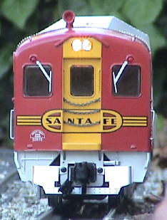
23 Jul 08 19 Dec 08 19 Dec 08 20 Dec 08 19 Dec 08 20 Dec 08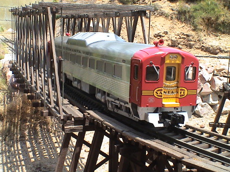 The Budd RDC
is a diesel hydraulic rail car built during the period of 1949 to 1962.
More details on the prototype can be found on Wikipedia.
The Budd RDC
is a diesel hydraulic rail car built during the period of 1949 to 1962.
More details on the prototype can be found on Wikipedia.
The Aristo model of the RDC uses a similar extrusion to their streamliner. The car is powered by two ball bearing motor blocks with traction tires on two wheels on each truck. The unit is equipped with a smoke unit, lighting, a speaker, a DCC connector (accessible from the bottom) and a basic sound connector (also accessible from the bottom).
Santa Fe did indeed have two RDC cars, DC191 and DC192. This model is numbered DC191. These two RDC's were involved in a bad wreck in 1956 at Redondo Junction in Los Angeles. From the photos on the link, Aristo's paint scheme looks pretty accurate. DC-191 still exists, but it is not in very good condition.
The RDC is a very long car, longer than anything else that I have.
| Car | Length | Scale Length (1/29) | Typical Prototype Length |
|---|---|---|---|
| Aristo RDC | 32" over the end caps |
77' | 85' |
| Aristo Standard Heavyweight | 30" over the diaphragms |
72' | 72' |
| Aristo Streamliner | 27.5" over the diaphragms |
66' | 80' |
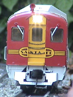
Like all rolling stock, the RDC has an "A" and a "B" end. For most freight cars, the difference is pretty minor, usually the difference is in the layout of the brake gear. On a regular passenger car, the restrooms are asymmetrical so the ends are somewhat different. On the RDC, the car is nearly symmetrical, the major spotting feature is the location of the radiator on the top of the car. On and RDC, the radiator is closer to the "A" end.
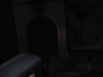
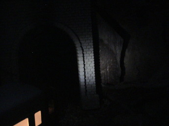
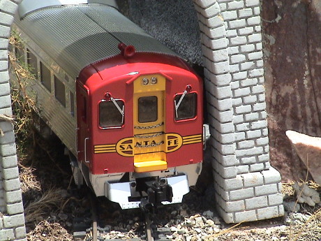 The Aristo RDC is a new benchmark
in clearance, or lack thereof. This is the tightest spot on the GIRR
and everything else clears it, including heavyweight coaches and a
Doodlebug (the previous record holder). The RDC whacked the tunnel
portal pretty good. I have since moved the track over a little and now
it just clears.
The Aristo RDC is a new benchmark
in clearance, or lack thereof. This is the tightest spot on the GIRR
and everything else clears it, including heavyweight coaches and a
Doodlebug (the previous record holder). The RDC whacked the tunnel
portal pretty good. I have since moved the track over a little and now
it just clears.
The RDC pulls quite well, much better than the prototype could. With it's weight (considerable) and the traction tires, it has good drawbar pull. I ran my standard tests, as detailed in my Tractive Effort Tests page. The RDC pulls better than most of the 4 axle locos that I have. The traction tires probably have a lot to do with this. A real RDC was only about 450 hp so it could handle maybe one trailer at best.
However, all the pulling power goes to naught because the end swing of the extra long RDC is so severe that it will pull the following car right off the track in turns less than 5' radius.
The unit picks up power on all eight wheels via the ball bearings and it does a good job. It ran smoothly without the need to clean the track.
The unit has two relatively anemic incandescent directional headlights and two red running lights at each end. The interior of the car is lighted through the frosted windows.
The unit ran smoothly and quietly right out of the box. Other than the typical DCC noise, it also ran well as analog loco on my DCC system. The lighting in that case, as is typical for an analog loco running on DCC, was non-directional. All the headlights and running lights came on in both directions. These will be directional and constant intensity when a DCC decoder is installed.
However, derailments were another matter. The car is very long and it is sensitive to changes in level. There are a couple of spots on the GIRR that obviously need attention as it systematically derailed at those two spots. The RDC is not particularly tolerant of out of level track. However, it was graceful going over leaves and twigs. I let it sweep the track of about a weeks worth of litter. It did derail on one particularly heavy twig that was laying right across the track, but it just crunched up the dried leaves.
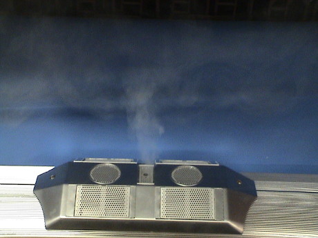 The RDC comes equipped with a smoke
unit similar to the one in the SD-45. This is an "intelligent"
unit in that it will sense when it runs out of fluid and shut off. The
instructions say that no more than 50 drops should be used. However, if
you use LESS than 50 drops, it won't smoke very long. It runs for about
2 minutes on 20 drops of Dept 56 Magic Smoke, then it shuts off.
The RDC comes equipped with a smoke
unit similar to the one in the SD-45. This is an "intelligent"
unit in that it will sense when it runs out of fluid and shut off. The
instructions say that no more than 50 drops should be used. However, if
you use LESS than 50 drops, it won't smoke very long. It runs for about
2 minutes on 20 drops of Dept 56 Magic Smoke, then it shuts off.
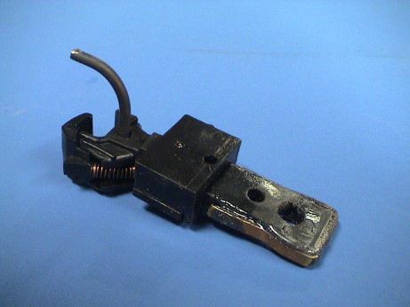
 The smoke unit is easily accessible
from under the "radiator" housing on the top of the unit. Remove two
screws from the top and the radiator comes off.
The smoke unit is easily accessible
from under the "radiator" housing on the top of the unit. Remove two
screws from the top and the radiator comes off.
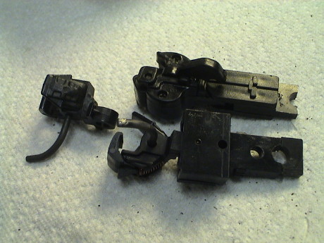
 The RDC comes equipped with
Aristo's knuckle coupler. There is also a "battery" connector hanging
out next to the coupler on each end. This coupler mounts in yet another
way and it takes some work to install a Kadee coupler.
The RDC comes equipped with
Aristo's knuckle coupler. There is also a "battery" connector hanging
out next to the coupler on each end. This coupler mounts in yet another
way and it takes some work to install a Kadee coupler.
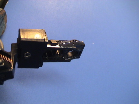
 My standard coupler, the
Kadee 831 will not mount easily. It'll come out at the wrong height,
the tang isn't quite long enough to use the existing hole in the 831
coupler body and even if a new hole was drilled, the coupler body would
not be able to rotate due to interference with the pilot mounting
structure. I looked for other standard Kadee configurations and I
didn't find another that would be easier to mount. So I got out the
razor saw and hacked. I cut off the end of the stock coupler and
attached it to the end of the Kadee coupler body with a little
Zap-A-Gap CA to hold it in place. I had to file out the notch on the
end of the Kadee 831 draft gear to make it large enough to fit over the
coupler mounting post.
My standard coupler, the
Kadee 831 will not mount easily. It'll come out at the wrong height,
the tang isn't quite long enough to use the existing hole in the 831
coupler body and even if a new hole was drilled, the coupler body would
not be able to rotate due to interference with the pilot mounting
structure. I looked for other standard Kadee configurations and I
didn't find another that would be easier to mount. So I got out the
razor saw and hacked. I cut off the end of the stock coupler and
attached it to the end of the Kadee coupler body with a little
Zap-A-Gap CA to hold it in place. I had to file out the notch on the
end of the Kadee 831 draft gear to make it large enough to fit over the
coupler mounting post.
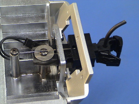
Mounted this way, the large offset coupler that comes with the Kadee 831 (the one in the box already) will be too high by about 200 mils. This means that I have to substitute the coupler for a medium offset coupler from a Kadee 836 set (shown separately). I had only one of those handy so I'll do the other end later.
 The Zap-A-Gap would not be
strong enough in tension to handle the draft load on the coupler so
I've beefed up the joint with Devcon Plastic Steel epoxy. When it has
set up, I'll drill a new hole in the back of the coupler body to
accommodate the centering spring as I have done on previous Kadee
conversions.
The Zap-A-Gap would not be
strong enough in tension to handle the draft load on the coupler so
I've beefed up the joint with Devcon Plastic Steel epoxy. When it has
set up, I'll drill a new hole in the back of the coupler body to
accommodate the centering spring as I have done on previous Kadee
conversions.
 The Kadee coupler is
installed with a medium offset coupler in the pocket. I had to do a
little bit of filing on the mount to allow it to swivel freely, but it
centers fine. I drilled a 0.040" hole in the back of the pocket to
accept the centering spring which needed just a little trimmed off the
end. All fits fine now and the coupler is at the right height.
The Kadee coupler is
installed with a medium offset coupler in the pocket. I had to do a
little bit of filing on the mount to allow it to swivel freely, but it
centers fine. I drilled a 0.040" hole in the back of the pocket to
accept the centering spring which needed just a little trimmed off the
end. All fits fine now and the coupler is at the right height.
As I was running the pulling power tests, I broke the coupler right off at the joint. This will require some rework. I roughed up the plastic everywhere the epoxy will touch it and I imbedded a couple of fine wires (resistor leads) into the epoxy fillets on each side.
Based on the derailments that I had during the pulling power tests I also suspect that the couplers will not be a whole lot of use anyway. The swing of this car is SO large, that it will probably mate only with similarly long cars, such as another RDC. S-curves, of which I have several, may not be tolerated at all with a MU RDC lashup. With a Streamliner in tow, the S-curves are tolerated only because the Streamliner has a truck mounted coupler. When going though an S-curve, both couplers are flexing to the side as far as they will go.
 The revised coupler mount with the
imbedded wires also broke. The epoxy still peeled off the edge of the
coupler mount. I don't give up easily though. Since the epoxy isn't
handling shear well I have rearranged things so that the epoxy will be
in compression. I cut and bent a piece of strip brass into a stirrup
and pinned it to the coupler body with a piece of music wire pressed
through the body. The wire can't be seen as it's under globs of epoxy.
Epoxy also fills the gap between the brass strap and the coupler body.
The draft forces are then applied to the mounting post via the wire,
the strap, epoxy in compression and the piece of the original
coupler.
The revised coupler mount with the
imbedded wires also broke. The epoxy still peeled off the edge of the
coupler mount. I don't give up easily though. Since the epoxy isn't
handling shear well I have rearranged things so that the epoxy will be
in compression. I cut and bent a piece of strip brass into a stirrup
and pinned it to the coupler body with a piece of music wire pressed
through the body. The wire can't be seen as it's under globs of epoxy.
Epoxy also fills the gap between the brass strap and the coupler body.
The draft forces are then applied to the mounting post via the wire,
the strap, epoxy in compression and the piece of the original
coupler.
Even this mount was a little too high so I substituted a zero offset coupler for the medium offset coupler. Then it was a tad too low so I "adjusted" the trip pin and called it done.
 I didn't want to do the
"B" end of the car the same way so this time I made my own draft gear
from 0.060" styrene sheet and I used a Kadee #836 coupler. A single
strip of styrene set the coupler to the right height when it was at the
end of the mounting post. I could have used washers below the strip,
but I didn't have any the right size so I used more styrene to make up
the 130 mil gap. The centering spring needed some bending to reach the
coupler body but it fit. This mount comes out at exactly the right
height and it has as much coupler swing as is allowed by the pilot
mount of the RDC.
I didn't want to do the
"B" end of the car the same way so this time I made my own draft gear
from 0.060" styrene sheet and I used a Kadee #836 coupler. A single
strip of styrene set the coupler to the right height when it was at the
end of the mounting post. I could have used washers below the strip,
but I didn't have any the right size so I used more styrene to make up
the 130 mil gap. The centering spring needed some bending to reach the
coupler body but it fit. This mount comes out at exactly the right
height and it has as much coupler swing as is allowed by the pilot
mount of the RDC.
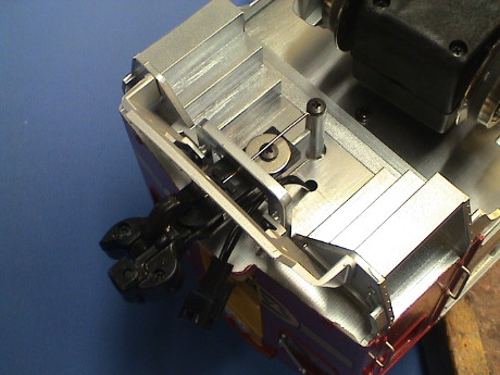
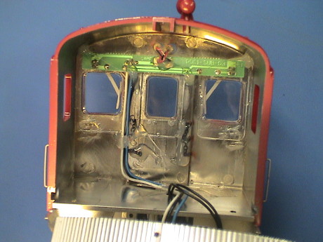
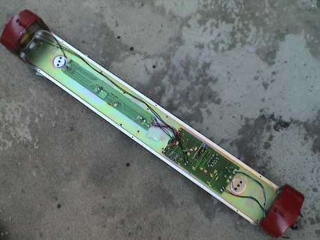 The RDC is not very hard to
get in to. There are 6 screws, 3 underneath each side, that hold the
shell to the frame. There are two more very tiny screws on the tops of
the end caps that hold the shell to the end caps. With those screws
removed, the shell can be lifted straight off.
The RDC is not very hard to
get in to. There are 6 screws, 3 underneath each side, that hold the
shell to the frame. There are two more very tiny screws on the tops of
the end caps that hold the shell to the end caps. With those screws
removed, the shell can be lifted straight off.
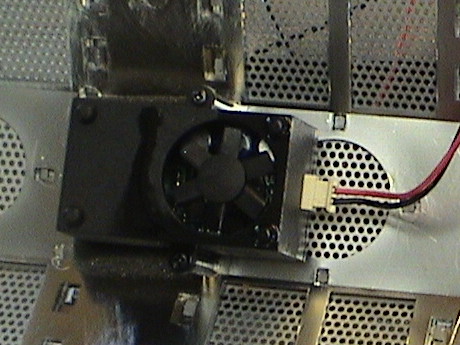
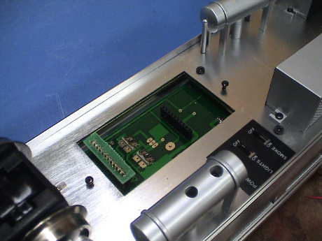
There are four printed wiring boards in the RDC. Two very small ones mount the headlights, these are in each end cap. The long skinny board is primarily there to hold three of the interior lights and the sound system connections. The main board is where all the action is.
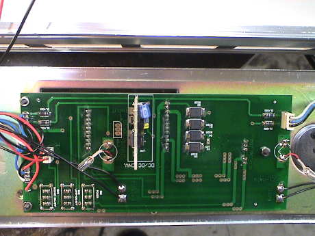 The main board contains the
DCC socket (other side), a Pulse Width Modulator daughter board, the
main rectifier diodes, the other two interior lights and the switches
(also on the other side). The PWM daughter board is a switchmode low
voltage regulator that power the lights at about 7 volts average.
The main board contains the
DCC socket (other side), a Pulse Width Modulator daughter board, the
main rectifier diodes, the other two interior lights and the switches
(also on the other side). The PWM daughter board is a switchmode low
voltage regulator that power the lights at about 7 volts average.
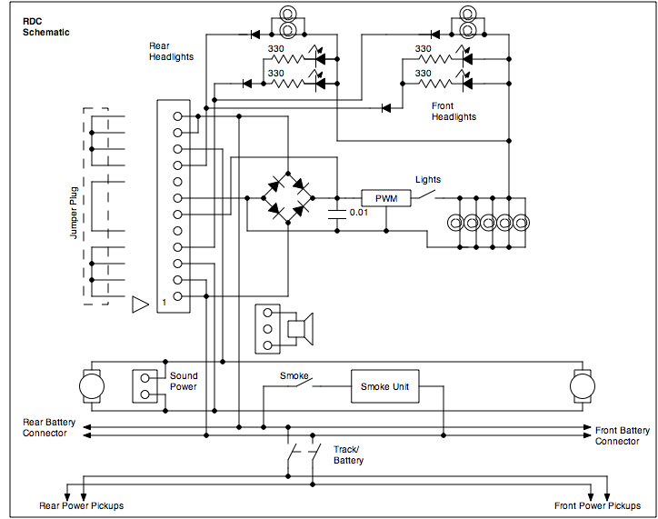 The schematic is pretty straightforward. The
main power bus is the battery connector bus that runs the length of the
loco. A switch allows the power pickups to be disconnected. Power is
routed to the DCC socket. If no decoder or RX is installed, a small
jumper board connects the power to the motor and to the returns for the
headlight circuits. Directionality is provided by diodes in the
headlight circuits. The smoke unit runs directly from the battery
bus.
The schematic is pretty straightforward. The
main power bus is the battery connector bus that runs the length of the
loco. A switch allows the power pickups to be disconnected. Power is
routed to the DCC socket. If no decoder or RX is installed, a small
jumper board connects the power to the motor and to the returns for the
headlight circuits. Directionality is provided by diodes in the
headlight circuits. The smoke unit runs directly from the battery
bus.
If a DCC decoder is installed, then the decoder is allowed to control the headlights and the motor.
Power to a sound system is provided by the motor circuit. Any system that can be powered from a "track" input can plug directly in to the 2 pin socket on the skinny board.
 The original
incandescent headlights were pretty weak. They are soldered in parallel
to two pads on the headlight PWB and held in place with great gobs of
hot glue.
The original
incandescent headlights were pretty weak. They are soldered in parallel
to two pads on the headlight PWB and held in place with great gobs of
hot glue.
Since I had the "B" end of the car off anyway to reattach the side windows that fell off during shipment, I changed out the incandescent lamps to white LEDs. White LED headlights aren't much more highly visible in bright sunlight, as a matter of fact, they may be LESS visible from some viewing angles due to the narrow angle of the beam. However, in dim light or at night, there is no comparison. A white LED is a real headlight which casts a real beam.
The end caps come off with two screws underneath and one VERY SMALL screw set into the roof just behind the cap. Be sure that you use a proper jeweler's screwdriver on this one, if you ruin it, you'll have to drill out out.
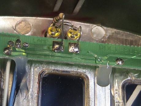 A standard 5 mm LED fits in
the lenses just fine. I wired the two LEDs in series with a 750 ohm
current limiting resistor. Other values between 620 and 1000 ohms will
also work. 750 ohms is just right for 20 mA from my 22 volt DCC track
voltage. The LED's connect between them long lead to short lead. The
resistor can be in series with either lead. The resistor current
limiting doesn't provide constant intensity lighting but it does well
enough. This RDC will be converted to DCC eventually anyway and
constant intensity will come automatically with DCC.
A standard 5 mm LED fits in
the lenses just fine. I wired the two LEDs in series with a 750 ohm
current limiting resistor. Other values between 620 and 1000 ohms will
also work. 750 ohms is just right for 20 mA from my 22 volt DCC track
voltage. The LED's connect between them long lead to short lead. The
resistor can be in series with either lead. The resistor current
limiting doesn't provide constant intensity lighting but it does well
enough. This RDC will be converted to DCC eventually anyway and
constant intensity will come automatically with DCC.
I didn't try to get the polarity right by design, I just put them in one way and they didn't work. So I turned them around as a set and then they worked fine. Before I installed the LEDs, I touched up the lenses with a very light coat of Tamiya X-24 Clear Yellow to cut the blue cast just a little.
The LEDs don't need any further support beyond that provided by the leads so it is not necessary glue them in place.
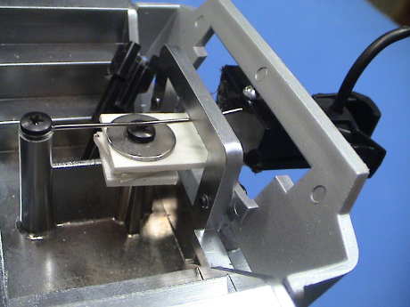
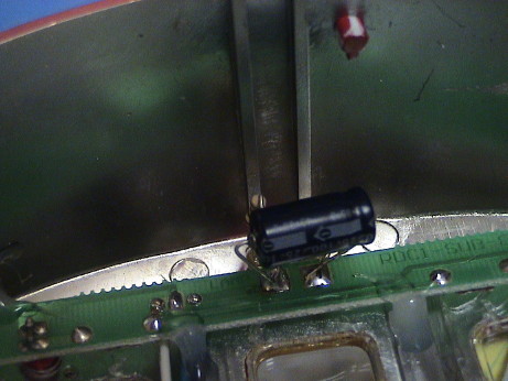 During the initial round of
tests, I observed that the LEDs were brighter, but not as much brighter
as I expected. I found the original headlights on the bench and tested
them and I found that they were about 12 volt bulbs so I suspected that
there was some sort of regulator involved. I peeled the end cap off the
RDC to check the LED current and I found that it was really low, no
more than 3 mA. This is not enough, 15 to 20 mA is desirable. I put a
scope on the pads on the board and I found that the signal wasn't DC.
The headlights are run from a pulse width modulator running at about 6
kHz. The peak current was about right, but the duty factor was low,
less than 20%. I wanted the LEDs to run at 100% duty factor so I
installed a 100 uF capacitor on the headlight pads. The signal on the
LEDs smoothed out to DC and the current settled at 15 mA. Now the
headlights are much brighter. This worked until I installed DCC and I
had to make changes, see the DCC section below.
During the initial round of
tests, I observed that the LEDs were brighter, but not as much brighter
as I expected. I found the original headlights on the bench and tested
them and I found that they were about 12 volt bulbs so I suspected that
there was some sort of regulator involved. I peeled the end cap off the
RDC to check the LED current and I found that it was really low, no
more than 3 mA. This is not enough, 15 to 20 mA is desirable. I put a
scope on the pads on the board and I found that the signal wasn't DC.
The headlights are run from a pulse width modulator running at about 6
kHz. The peak current was about right, but the duty factor was low,
less than 20%. I wanted the LEDs to run at 100% duty factor so I
installed a 100 uF capacitor on the headlight pads. The signal on the
LEDs smoothed out to DC and the current settled at 15 mA. Now the
headlights are much brighter. This worked until I installed DCC and I
had to make changes, see the DCC section below.
 Since
I initially only converted one end of the car, I was able to compare
the brightness of the stock headlights vs the LED headlights. Even in
daylight, the difference is quite pronounced.
Since
I initially only converted one end of the car, I was able to compare
the brightness of the stock headlights vs the LED headlights. Even in
daylight, the difference is quite pronounced.
 It's easier to see when
the headlight beam is reflected off of another surface. In this case,
the LEDs (on the right) can be seen to be brighter.
It's easier to see when
the headlight beam is reflected off of another surface. In this case,
the LEDs (on the right) can be seen to be brighter.
Eventually, I also did the "B" end of the car the same way but with a different 20° LED from TheLEDLight.com. These are newer and brighter than the ones than the much older ones that I had been using.
 The RDC comes equipped
with a "DCC" socket. This is the same socket as used in most other late
model Aristo locos. It will accept a "plug-n-play" DCC decoder or a
Crest Train Engineer receiver. The socket is accessible inside an
equipment box underneath the RDC, loosening two screws gets you in.
There is a jumper board on the 12 pin connector to allow the loco to
run with straight track power. A plug and play DCC decoder will go in
this socket with the jumper board removed. There is a 10 pin socket
that is not used electrically. It serves only to support the other end
of the decoder board.
The RDC comes equipped
with a "DCC" socket. This is the same socket as used in most other late
model Aristo locos. It will accept a "plug-n-play" DCC decoder or a
Crest Train Engineer receiver. The socket is accessible inside an
equipment box underneath the RDC, loosening two screws gets you in.
There is a jumper board on the 12 pin connector to allow the loco to
run with straight track power. A plug and play DCC decoder will go in
this socket with the jumper board removed. There is a 10 pin socket
that is not used electrically. It serves only to support the other end
of the decoder board.
 I ordered a Digitrax
DG383AR decoder for the RDC. This is a completely new design compared
to the older Digitrax decoders that I had used and become disgusted
with. This one is silent running, has back EMF control and is
configured to plug right it.
I ordered a Digitrax
DG383AR decoder for the RDC. This is a completely new design compared
to the older Digitrax decoders that I had used and become disgusted
with. This one is silent running, has back EMF control and is
configured to plug right it.
The decoder worked right off. I had only one difficulty, when I turned the headlights on and tried to run the RDC in the direction with the new LED headlight (described below), the thing just freaked out. I revised the LED headlight circuit and all got well again. Others have also had difficulty with noise from the PWM circuit in the newer Aristo locomotives interfering with the processor on a DCC decoder. Apparently, the storage capacitor was coupling enough pulsed current back to the decoder for the noise bother the decoder.
I had to rip out the capacitor that I had used to help brighten the LED and reduce the value of the current limiting resistor to 51 ohms. This allows the pulsed current to the LEDs to reach about 150 mA at about a 10% duty factor. The LEDs won't produce intense light as efficiently at high peak currents, but they will still get bright and the low duty factor keeps them from burning up. I have some more data on the performance of a white LED under DC and pulsed conditions on my White LED Tips page.
The RDC with the Digitrax decoder runs quite well. With the back-EMF enabled but set to minimal lock (CV57=001) it will run very slowly. It takes 50 sec to go one foot.
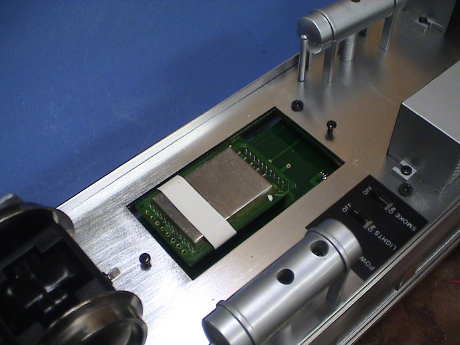
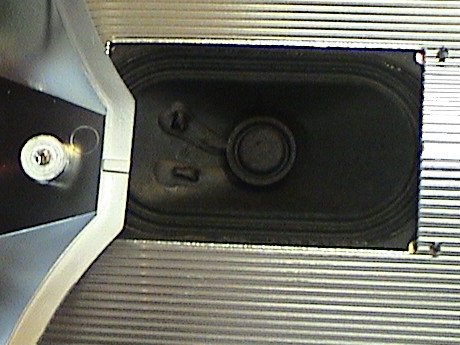 A
speaker is preinstalled under the radiator as well. It is prewired to a
socket underneath the RDC.
A
speaker is preinstalled under the radiator as well. It is prewired to a
socket underneath the RDC.
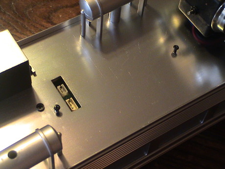 Loosening another two
screws on a second equipment box reveals two connectors for the sound
system. The 3 pin connector goes to the speaker. The 2 pin connector
goes to the motor power bus. A DCC installation may require some
customization here depending on the sound system selected.
Loosening another two
screws on a second equipment box reveals two connectors for the sound
system. The 3 pin connector goes to the speaker. The 2 pin connector
goes to the motor power bus. A DCC installation may require some
customization here depending on the sound system selected.
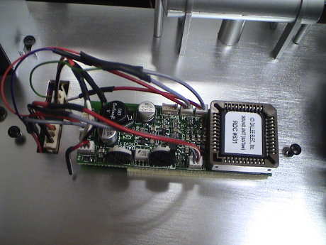 I finally elected to install
a Dallee sound system in the
RDC. I needed to get into the RDC to route some more wires because the
Dallee board needed more than just the motor and speaker connections.
It also needs track power and I elected to wire up all four functions
that it supports.
I finally elected to install
a Dallee sound system in the
RDC. I needed to get into the RDC to route some more wires because the
Dallee board needed more than just the motor and speaker connections.
It also needs track power and I elected to wire up all four functions
that it supports.
The track power wires were soldered to a set of the "battery" contacts on the main PWB. This means that the sound system is a load on the track all the time and it will complicate using a programming track. I don't anticipate needing to use the programming track again, but if it is needed, I can loosen the two screws to remove the box covering the sound system and pull the track power plug until I am done on the programming track.
The installation went well, no problems were encountered. However, I don't think that the sound program really represents an RDC. Real RDC's had a hydraulic torque converter transmission (similar to a tank) such that the engine speed steadily increased from idle to maximum RPM. There is no notching or transition that would be typically found on a diesel electric loco. This system doesn't appear to notch, but it does go through a transition where the engine speed decreases some before picking up again. In any event, it sounds like a diesel and it wasn't very expensive.
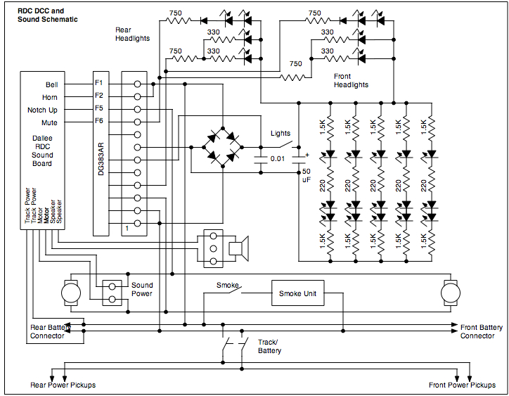 This is the schematic after I installed
DCC, sound and modified the lighting yet again. I never liked the
AristoCraft PWM boards. They put out too much noise and don't regulate
all that well. I removed the PWM by wicking all the solder off the pads
on the main board and pulled it out. I then jumpered the + input pad to
the + output pad. This puts rectified track voltage on all the lights.
Since the bulbs are rated for about 6 volts, they had to go too,
replaced by LEDs. The 51 Ω series resistor I had installed in the
LED headlights was changed out to a 750 Ω resistor. I removed the
diodes (on the main board) that were in series with the red rear end
lamps and installed a 750 Ω resistor there as well. These
resistors are about right to limit the current to all the LEDs to about
20 mA.
This is the schematic after I installed
DCC, sound and modified the lighting yet again. I never liked the
AristoCraft PWM boards. They put out too much noise and don't regulate
all that well. I removed the PWM by wicking all the solder off the pads
on the main board and pulled it out. I then jumpered the + input pad to
the + output pad. This puts rectified track voltage on all the lights.
Since the bulbs are rated for about 6 volts, they had to go too,
replaced by LEDs. The 51 Ω series resistor I had installed in the
LED headlights was changed out to a 750 Ω resistor. I removed the
diodes (on the main board) that were in series with the red rear end
lamps and installed a 750 Ω resistor there as well. These
resistors are about right to limit the current to all the LEDs to about
20 mA.
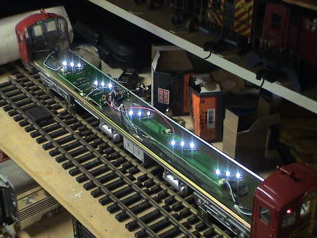 The five interior lamps
were replaced with white LED
strips. I had exactly five of them left over from previous lighting
conversions in heavyweight passenger
cars, streamliner
passenger cars and a Doodlebug.
The five interior lamps
were replaced with white LED
strips. I had exactly five of them left over from previous lighting
conversions in heavyweight passenger
cars, streamliner
passenger cars and a Doodlebug.
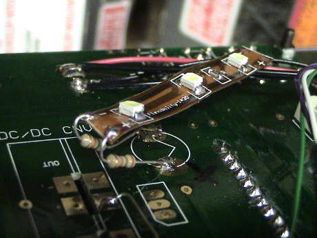 Each LED strip was
installed with two 1.5KΩ resistors to provide current limiting in
the positions of the original lamps. The strips were placed at an angle
so that one LED on each strip will shine on the cardboard reflector and
the 3rd one will sort of split it's light out each side. The strips are
so light and are sufficiently stiff that they are adequately supported
by the resistor leads.
Each LED strip was
installed with two 1.5KΩ resistors to provide current limiting in
the positions of the original lamps. The strips were placed at an angle
so that one LED on each strip will shine on the cardboard reflector and
the 3rd one will sort of split it's light out each side. The strips are
so light and are sufficiently stiff that they are adequately supported
by the resistor leads.
[ Home ] [ Up ] [ Previous Page ] [ Next Page ]
This page has been accessed times since 16 Jun 08.
© 2009 George Schreyer
Created 16 Jun 08
Last Updated May 15, 2009