 3 Sep 08
[ Home ] [ Up ] [ Previous Page ] [ Next Page ]
 Electric trolly cars have been around for a long
time. The first ones were installed by Frank Sprague at Richmond Va in 1888. In
many cities, they were the most practical way to get around. They were
much faster than horse drawn carts and could operate even when the
roads were so muddy that getting around in any vehicle other than a
horse was nearly impossible.
Electric trolly cars have been around for a long
time. The first ones were installed by Frank Sprague at Richmond Va in 1888. In
many cities, they were the most practical way to get around. They were
much faster than horse drawn carts and could operate even when the
roads were so muddy that getting around in any vehicle other than a
horse was nearly impossible.
More interesting information on the construction and operation of a turn of the century (the last century) trolly line can be found in this book.
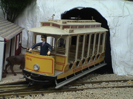
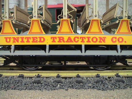
Bachmann has made, and may still make, models of closed and open sided trolly cars. The open cars were used primarily in the summer as they were much cooler than the closed cars. Of course, the closed cars were preferred in the winter and during bad weather.
I originally got this car in 1992 or 1993. I incorporated features of the GIRR Mountain Division right into the layout design to accommodate this car.
 The trolly line is a loop to loop in the upper right
portion of the track diagram. By test, I determined that the Bachmann
trolly could negotiate 2 foot DIAMETER curves and I needed the room so
that is what I used. Trolly cars were good at dealing with very tight
curves, this curve radius may be a little tighter than a prototype, but
not by much.
The trolly line is a loop to loop in the upper right
portion of the track diagram. By test, I determined that the Bachmann
trolly could negotiate 2 foot DIAMETER curves and I needed the room so
that is what I used. Trolly cars were good at dealing with very tight
curves, this curve radius may be a little tighter than a prototype, but
not by much.
The trolly used to have sliders on it, but the sliders would not work in the tight radius track so they were jettisoned quite quickly.
The line operates automatically using custom built circuitry to control the action. Both turnouts on the line are spring switches, one is LGB with the manual control box, and the other is also an LGB turnout but with a light coil spring in place of the manual control box which was just too stiff. The trolly makes two short timed stops in the town with smooth deceleration and acceleration and then makes a long stop behind a view block under the scenery to simulate it going off into the distance for awhile.
 The trolly has a single
motor block underneath. It originally ran very poorly. It made lots of
noise and wasn't smooth at all. I made many stabs at fixing it, to no
avail. After the trolly line had been built, I determined that it ran
so badly that my carefully designed smooth stop and start circuity
wasn't going to work because the trolly just would not run smoothly. I
bit the bullet and sent it, with $20, back to Bachmann for repair. When
it came back, it had a redesigned bottom end and it actually ran pretty
well.
The trolly has a single
motor block underneath. It originally ran very poorly. It made lots of
noise and wasn't smooth at all. I made many stabs at fixing it, to no
avail. After the trolly line had been built, I determined that it ran
so badly that my carefully designed smooth stop and start circuity
wasn't going to work because the trolly just would not run smoothly. I
bit the bullet and sent it, with $20, back to Bachmann for repair. When
it came back, it had a redesigned bottom end and it actually ran pretty
well.
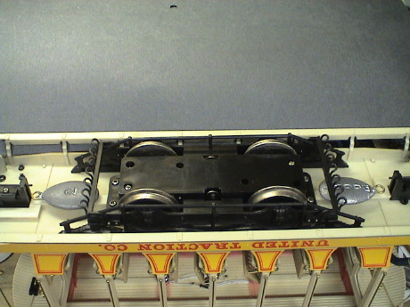
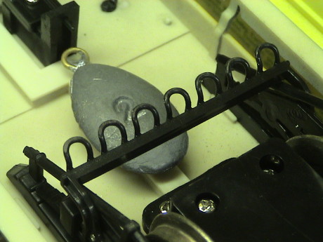
I determined that the trolly was a little light so I have added 4 oz of lead fishing weights underneath.
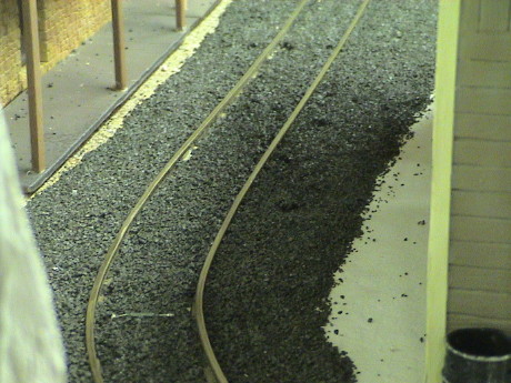
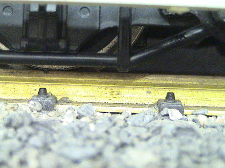
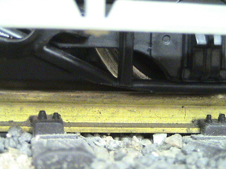
 The trolly always had a
tendency to derail right where the lead picture was taken, just exiting
a tunnel portal. When I simply pushed the trolly through the whole
region of the derailments, I found that it would catch on something.
The pilot was actually dragging on the rail and catching in the rail
gap at the insulated rail joiners. It took me years to actually dig in
and solve this simple problem.
The trolly always had a
tendency to derail right where the lead picture was taken, just exiting
a tunnel portal. When I simply pushed the trolly through the whole
region of the derailments, I found that it would catch on something.
The pilot was actually dragging on the rail and catching in the rail
gap at the insulated rail joiners. It took me years to actually dig in
and solve this simple problem.
 When I applied a dark gray
crushed rock to the trolly line in the town to simulate a roadway, I
really started to have problems. The trolly would jump and hop around
like mad, derailing at many spots. I had cleaned off the track and
cleared out the flangeways, but it didn't help.
When I applied a dark gray
crushed rock to the trolly line in the town to simulate a roadway, I
really started to have problems. The trolly would jump and hop around
like mad, derailing at many spots. I had cleaned off the track and
cleared out the flangeways, but it didn't help.
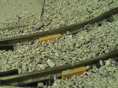
Just for reference, one of the reed switches that controls a trolly stop can be seen just sticking out of the ballast. The magnetic field of the motor itself is sufficient to trip these switches.
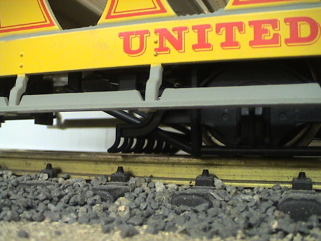
 The problem is that
the pilot is just too low. The photo shows that the lowest parts are
heavily abraded from years of scraping on the rails. Now it was
scraping on the newly applied roadway OUTSIDE the rails. It would also
catch on the rail joint at the traditional derailment location and pop
the trolly off the track so that it ended up derailed on the following
turnout which is where I thought that the problem really was. After I
just removed the whole sideframe and pilot assembly and ran the trolly,
it behaved fine.
The problem is that
the pilot is just too low. The photo shows that the lowest parts are
heavily abraded from years of scraping on the rails. Now it was
scraping on the newly applied roadway OUTSIDE the rails. It would also
catch on the rail joint at the traditional derailment location and pop
the trolly off the track so that it ended up derailed on the following
turnout which is where I thought that the problem really was. After I
just removed the whole sideframe and pilot assembly and ran the trolly,
it behaved fine.
Pilots like these were purposely built really low to the track in real street railways to scrape junk off the right of way which was usually a street. There could be all kinds of crud there that could derail a trolly car if it was allowed to get under the wheels. However, in the model, this item is for decoration only and it doesn't need to be quite so low such that it actually scrapes on the track.
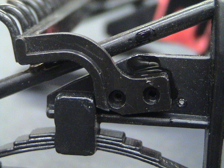
 This photo shows how
low the pilot was without modification.
This photo shows how
low the pilot was without modification.
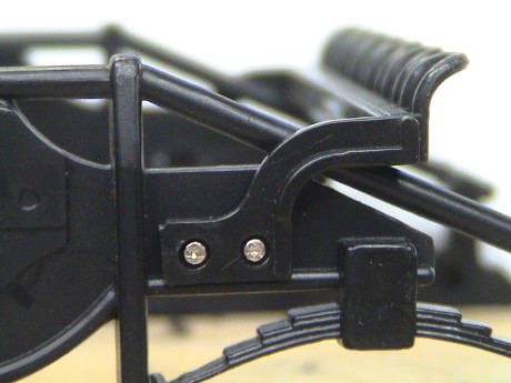 The pilot assembly is
mounted with four really small screws. It cannot be simply repositioned
by opening up the screw holes a little due to interference with a
support rod.
The pilot assembly is
mounted with four really small screws. It cannot be simply repositioned
by opening up the screw holes a little due to interference with a
support rod.
 I elected to abandon the
screws entirely and move the pilot forward just a little to allow it to
be canted upward some. To do this a small locator tab needs to be
trimmed off the back and a corner trimmed off the front, quick work
with a pair of flush cutters. It is then reattached with Zap-A-Gap CA.
An additional fillet of Zap-A-Gap has been applied to the support rod
to strengthen the joint.
I elected to abandon the
screws entirely and move the pilot forward just a little to allow it to
be canted upward some. To do this a small locator tab needs to be
trimmed off the back and a corner trimmed off the front, quick work
with a pair of flush cutters. It is then reattached with Zap-A-Gap CA.
An additional fillet of Zap-A-Gap has been applied to the support rod
to strengthen the joint.
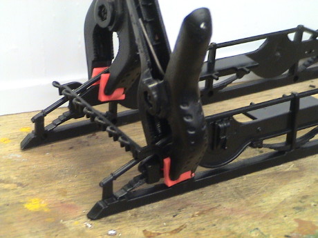 Even though Zap-A-Gap sets up
pretty quickly, for maximum strength, it should be left clamped and
undisturbed for at least an hour.
Even though Zap-A-Gap sets up
pretty quickly, for maximum strength, it should be left clamped and
undisturbed for at least an hour.
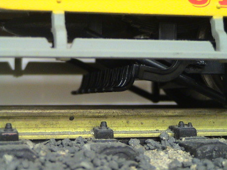 With this modification, the trolly pilot is high enough
to clear any practical obstacle.
With this modification, the trolly pilot is high enough
to clear any practical obstacle.
 However, when I
retested the trolly with the pilot problem solved, I found another
problem. There is a protrusion on the sideframe rods that sticks down,
sometimes lower than the railheads. This tended to catch in the frog of
an LGB turnout when running trailing point from the curved side also
causing the trolly to pop up.
However, when I
retested the trolly with the pilot problem solved, I found another
problem. There is a protrusion on the sideframe rods that sticks down,
sometimes lower than the railheads. This tended to catch in the frog of
an LGB turnout when running trailing point from the curved side also
causing the trolly to pop up.
 Some quick work
with flush cutters removed this bump and makes the transition smooth so
that if it does actually hit something again, the trolly will slide
over it instead of hanging up.
Some quick work
with flush cutters removed this bump and makes the transition smooth so
that if it does actually hit something again, the trolly will slide
over it instead of hanging up.
The Bachmann Trolly never ran really well. When it was new, it was terrible. I sent it back to Bachmann for repair and it came back with a different mechanism. It ran SO much better than the original mechanism that I thought that it was going to work. I ran it this way for 14 years so I guess that it was more or less adequate. However, it was never as good as it could be.
After those 14 years, I finally ballasted the track that it was running on. I checked the track carefully for level before I cast it in concrete, as it were. However, something happened on one spot where the trolly normally makes a station stop. The track drifted slightly out of level by less than a quarter bubble, but this was enough to cause problems.
The wheelbase of the trolly is quite rigid. When the track changes in level between the two axles, a wheel will lift. The three remaining wheels do not have reliable enough power pickup and the trolly would just sit there until nudged. Even though the track was not perfect, it was as close as it could be expected to stay as my benchwork shifts over time. This something that had to be fixed.
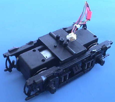
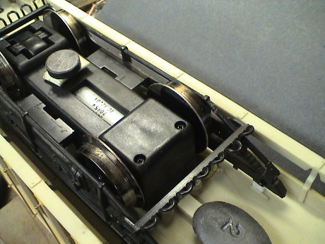
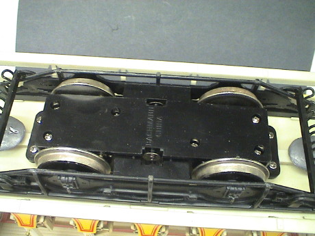 The stock Bachmann
Trolly brick mounts to the floor of the trolly. The sideframe assembly
mounts to the brick via some small, and fragile, pins.
The stock Bachmann
Trolly brick mounts to the floor of the trolly. The sideframe assembly
mounts to the brick via some small, and fragile, pins.
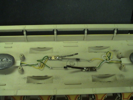 The brick has
two metal contacts on top that are contacted by two metal tabs on the
bottom of the trolly. The diodes are for the directional
headlights.
The brick has
two metal contacts on top that are contacted by two metal tabs on the
bottom of the trolly. The diodes are for the directional
headlights.
 The brick
itself has a small can motor and reduction gearing. The axles ride in
grooves in the brick housing, this is part of the problem. The trolly
has a 4 point support which makes it inherently unstable. One wheel
will usually be lifted from the track as the axles are not allowed very
much slop. I first considered grinding on the grooves that one axle
rides in to allow one axle to move around a little. This is not really
a true 3 point mount, but it might have gotten close. However, the rest
of the brick was still marginal so I just elected to replace the whole
damn thing.
The brick
itself has a small can motor and reduction gearing. The axles ride in
grooves in the brick housing, this is part of the problem. The trolly
has a 4 point support which makes it inherently unstable. One wheel
will usually be lifted from the track as the axles are not allowed very
much slop. I first considered grinding on the grooves that one axle
rides in to allow one axle to move around a little. This is not really
a true 3 point mount, but it might have gotten close. However, the rest
of the brick was still marginal so I just elected to replace the whole
damn thing.
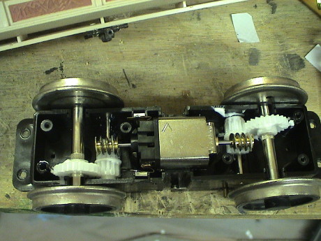
 What I elected to replace it with was an
Aristo Diesel brick. This is the latest ball bearing design with
integrated power pickups. It is also a 3 point mount. The two wheels
attached to the rocking gearbox act as one point of support at the
center of the axle. The other two fixed wheels are the other two
points. All 4 wheels will touch the track almost all the time, even if
the track is quite wavy.
What I elected to replace it with was an
Aristo Diesel brick. This is the latest ball bearing design with
integrated power pickups. It is also a 3 point mount. The two wheels
attached to the rocking gearbox act as one point of support at the
center of the axle. The other two fixed wheels are the other two
points. All 4 wheels will touch the track almost all the time, even if
the track is quite wavy.
This particular part, the ART-29351, is intended to be a replacement part for any of the U25B, FA-1, FB-1 or RS-3 trucks of any vintage. It can be found at train discounters for about $40. The wiring harness supplied works with all but the very oldest bricks which came in locos packed in black or blue boxes. For these, cutting and splicing of the wiring is required. It comes with a AAR Type B truck sideframe, these are for show only and I don't use them for this modification.
The Aristo ball bearing brick is a very smooth running mechanism that has been fine tuned over time to be strong, reliable and quiet.
I was concerned that it would not run on my trolly track which is bent to a 2' diameter. When I put the brick by itself (jumpered as shown in the photo to allow it to run), I was pleased to find that the Aristo brick handles the tight curve BETTER than the Bachmann brick. There is one spot that is a little too tight. The Bachmann brick used to squeeze up just a little but it never derailed. The Aristo brick has no such problem at that spot.
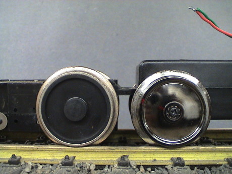 The
physical dimensions of the Bachmann brick and the Aristo brick are a
little different. The Bachmann brick sits lower, it has bigger wheels, smaller flanges
and a shorter wheelbase by about a half inch. None of this is a big
problem, but the trolly will ride about 0.2" higher than it used
to.
The
physical dimensions of the Bachmann brick and the Aristo brick are a
little different. The Bachmann brick sits lower, it has bigger wheels, smaller flanges
and a shorter wheelbase by about a half inch. None of this is a big
problem, but the trolly will ride about 0.2" higher than it used
to.
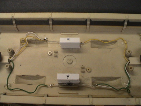 I
fabricated a mount for the Aristo brick using styrene. The blocks are
0.58" high by 0.25 inches wide. I used the screws that had attached the
Bachmann brick to the trolly to mount the Aristo brick, although I did
open up the mounting holes on the Aristo brick a little to provide some
fine adjustment for the position of the brick when finally mounted.
I
fabricated a mount for the Aristo brick using styrene. The blocks are
0.58" high by 0.25 inches wide. I used the screws that had attached the
Bachmann brick to the trolly to mount the Aristo brick, although I did
open up the mounting holes on the Aristo brick a little to provide some
fine adjustment for the position of the brick when finally mounted.
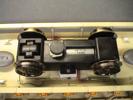 The
Aristo brick mounts close to the floor. I could have got it a little
closer by grinding off some tabs on the floor of the trolly, but I
still needed some room for wire clearance so the brick rides about 80
mils off the floor.
The
Aristo brick mounts close to the floor. I could have got it a little
closer by grinding off some tabs on the floor of the trolly, but I
still needed some room for wire clearance so the brick rides about 80
mils off the floor.
I cut off the connectors as they were unnecessary in this application and wired the red and black wires to one side of trolly wiring and the orange and green wires to the other. I elected to set the rocking axle as the "front" and I simply tested the polarity of the wiring until the trolly ran in the right direction and matched the headlights.
 The
sideframe is designed to mount to the side of the brick. I could have
drilled some new holes in the brick and mounted the sideframe the same
way, but I elected instead to mount it to the floor on 0.25" high
standoffs. When I took this picture, I noticed that I forgot to cut off
the tabs that reach to the sides of the brick. It's not a big problem
until I elect to remove the brick for some reason, then I'll have to
cut them off.
The
sideframe is designed to mount to the side of the brick. I could have
drilled some new holes in the brick and mounted the sideframe the same
way, but I elected instead to mount it to the floor on 0.25" high
standoffs. When I took this picture, I noticed that I forgot to cut off
the tabs that reach to the sides of the brick. It's not a big problem
until I elect to remove the brick for some reason, then I'll have to
cut them off.
This particular sideframe is NOT the same one that I modified for clearance earlier. This is one that came with the returned brick, but it was damaged. 3 of the 4 mounting pins had been sheared off during shipment. Bachmann sent me another sideframe assembly which is the one that I modified to raise the pilots. It is still attached to the Bachmann brick. For this brick swap, I used the one with the sheared pins as I was going to cut them off anyway.
I had to mount a magnet on the Aristo brick to trip the reed switches that define the station stops. No magnet was necessary on the Bachmann brick as it's motor had such a strong external magnetic field that it tripped the reed switches by itself.
 The finished
job doesn't look half bad. The step is a little higher than it used to
be and if you look closely, you'll see that the wheels don't line up
with the journals, but it doesn't show from a distance.
The finished
job doesn't look half bad. The step is a little higher than it used to
be and if you look closely, you'll see that the wheels don't line up
with the journals, but it doesn't show from a distance.
The trolly runs MUCH better now, it starts smoother, stops smoother, and makes less noise. It also coasts a little further so I may have to adjust the position of one of the reed switches in the track by about 4" but this is no big deal.
[ Home ] [ Up ] [ Previous Page ] [ Next Page ]
This page has been accessed times since 4 Jul 08.
© 2008-2009 George Schreyer
Created 4 Jul 08
Last Updated May 15, 2009