Aristo Center Cab Switcher Tips
[ Home ] [ Up ] [ Previous Page
] [ Next Page ]
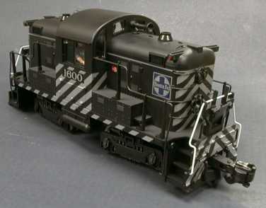 The Aristo Center Cab Switcher is a small
diesel locomotive modeled after a generic design of many small
industrial engines. There was no real prototype for this loco, but
it is credible in size and proportion. Many small switchers were
made with a center cab and a small (150 to 300 hp) engine/generator
set under each hood.
The Aristo Center Cab Switcher is a small
diesel locomotive modeled after a generic design of many small
industrial engines. There was no real prototype for this loco, but
it is credible in size and proportion. Many small switchers were
made with a center cab and a small (150 to 300 hp) engine/generator
set under each hood.
Aristo has apparently taken two short hoods, the cab and battery
boxes from their RS-3 and put them on a new frame with a new die
cast power brick. Unlike the L'il Critter, this locomotive has
engine exhaust ports. There are NO smoke
units.
Contents
Performance and Detail
 The Center Cab is a very smooth and quiet engine.
There is some audible gear noise, but the sound of the wheels on
the rails is louder than the mechanism. The engine is moderately
weighted and has good pulling power. It won't pull as well as the
larger heavier diesels, but since the motors are full sized, a
little weight in the body may improve that. I did run my standard
Tractive Effort
Tests on the center cab and it did fairly well, pulling about
as well as other Aristo diesels that haven't had additional weight
installed. Most of the engine weight is in the truck castings,
there are no internal body weights. There are also no traction
tires.
The Center Cab is a very smooth and quiet engine.
There is some audible gear noise, but the sound of the wheels on
the rails is louder than the mechanism. The engine is moderately
weighted and has good pulling power. It won't pull as well as the
larger heavier diesels, but since the motors are full sized, a
little weight in the body may improve that. I did run my standard
Tractive Effort
Tests on the center cab and it did fairly well, pulling about
as well as other Aristo diesels that haven't had additional weight
installed. Most of the engine weight is in the truck castings,
there are no internal body weights. There are also no traction
tires.
The slow speed performance is good, the slowest steady speed is
about 1 tie per second either loaded or running light. The top
speed is lower than other diesels, this locomotive more closely
matches the top speed of a C-16 than the other Aristo Diesels.
Typical industrial diesels could not exceed 40 mph due to their
non-swinging truck design. The truck sideframe models a welded up
truck similar to ones found on many small engines.
There are two switches underneath the loco for the motor and the
non existent smoke. These can be reached while the loco is still on
the track.
The paint job is a little more complete than the older RS-3's.
On this unit, painted in an ATSF style, the ladders and their metal
eyelets are all painted.
The wheel treads are wider than most wheels. This doesn't seem
to harm anything, but the engine looks a little odd from the
bottom. After extended running on my very dirty track, the wheels
picked up a slight haze, but there was no sign of pitting. Power
pickup was good considering the track it was running on which
probably hasn't been cleaned since last year. The engine did
respond to the bad track by speeding and slowing as it gained and
lost power, but it did so smoothly without the jerkiness of some
locos. It never did actually stall.
[ Top ]
Scale and Clearance
This is a very short locomotive so that it will handle tight
turns quite well. It has minimal overhang under any conditions so
that there are likely few railroads it won't fit on. The locomotive
is 12" long over the end steps and 15" long over the coupler faces.
The engine is 4" wide and 5-5/8" tall. The wheelbase of the truck
is 2.343". The trucks are 5.3" on center.
Since there isn't a real prototype for this engine, its "scale"
is open to interpretation. However, the engine size is consistent
with the 1/29 scale of the rest of the Aristo product line.
[ Top ]
Center Cab Power Bricks
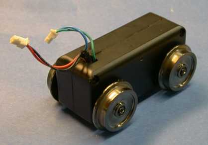 The Center Cab brick is a die cast metal
assembly. It is self contained and is very easy to remove from the
loco. There are two screws in sides of the A-frame that mounts the
truck. Removal of these screws releases the truck. The wiring is
connected to the loco with two plugs. These are differently sized
and keyed so that it is not possible to switch them or plug them in
backwards.
The Center Cab brick is a die cast metal
assembly. It is self contained and is very easy to remove from the
loco. There are two screws in sides of the A-frame that mounts the
truck. Removal of these screws releases the truck. The wiring is
connected to the loco with two plugs. These are differently sized
and keyed so that it is not possible to switch them or plug them in
backwards.
There are four screws on each side that hold the brick halves
together. To disassemble the brick, remove two wheels on one side
by removing the screws in the center of the wheels. The wheels are
centered on the axles with tapers and may bind a little, but a
little prying will pop them off. Then remove the four screws on
that side and pull the halves apart. The screws that hold the case
halves together are anchored in plastic insulating spacers.
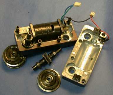 The truck
has a conventional can motor and worm gear drive. The motor has a
bypass capacitor and a device that appears to be a surge suppressor
soldered across its terminals. The motor is also wrapped in
electrical tape to insulate the can from the dicast case halves.
The power pickup wires are connected through lugs screwed to each
case half. Note that the wires are just crimped into the lugs and
can come out. This may not be visible due to the sleeving. If you
have a truck apart, it might be reasonable to cut off the sleeving,
remove the wire from the lug, put some more sleeving on the wire,
solder it back to the lug and then heat shrink the sleeving over
the soldered joint.
The truck
has a conventional can motor and worm gear drive. The motor has a
bypass capacitor and a device that appears to be a surge suppressor
soldered across its terminals. The motor is also wrapped in
electrical tape to insulate the can from the dicast case halves.
The power pickup wires are connected through lugs screwed to each
case half. Note that the wires are just crimped into the lugs and
can come out. This may not be visible due to the sleeving. If you
have a truck apart, it might be reasonable to cut off the sleeving,
remove the wire from the lug, put some more sleeving on the wire,
solder it back to the lug and then heat shrink the sleeving over
the soldered joint.
Each axle runs in two ball bearings that are pressed on the
axle. Power is picked up on every wheel and transferred to the case
halves through the bearings. These bearings should provide a long
bearing life, even if the loco is more heavily weighted.
 Older Aristo bricks
used screws as thrust bearings and sometimes they would squeak
loudly. Also, if the screws were misadjusted, either the motor
bearings would have to take up the thrust or the lash screws would
add drag as the adjustment was quite critical. This brick uses a
spring loaded thrust bearing instead so that adjustment is not
required. The thrust bearing does not add appreciably to motor
drag.
Older Aristo bricks
used screws as thrust bearings and sometimes they would squeak
loudly. Also, if the screws were misadjusted, either the motor
bearings would have to take up the thrust or the lash screws would
add drag as the adjustment was quite critical. This brick uses a
spring loaded thrust bearing instead so that adjustment is not
required. The thrust bearing does not add appreciably to motor
drag.
[ Top ]
Couplers
The Center Cab comes with standard Aristo knuckle couplers body
mounted and a set of hook and loop couplers in the box. The
existing couplers extend way out from the engine but they do work
with other Aristo rolling stock on 2' radius curves. On S curves,
the couplers get pretty contorted but they still work.
There are probably many ways to install Kadee couplers, but I
choose to use a method similar to one that I used on the RS-3. I
have a box if Kadee #831's so that I was inclined to use this
standard truck mount coupler. The coupler mount is similar to the
RS-3, but it isn't exactly the same. The post on an RS-3 has a
ridge at the right height to position a modified Kadee #831. The
Center Cab post does not have this ridge so that it must be
modified somewhat to mount a Kadee.
 The post is
just under 0.25" in diameter and is nearly the right height to hold
a #831 if the mounting hole on the #831 is drilled out to 0.25".
The coupler box then rests on the pilot and the whole assembly
comes out just a tad higher than the optimum height. The coupler
cannot droop because it is supported by the pilot. However, the
coupler can slide up on the post unless something stops it. The
RS-3 had ridges at the right spot, but these ridges are missing on
the Center Cab. I cut a short piece of 0.25" ID brass tubing and
slid it over the post. With the coupler box in place, I pushed the
tube down to the right position with a toothpick and then applied a
drop of Zap-CA to hold it in place. The existing coupler centering
spring must be trimmed shorter so that it will fit in a #70 hole
drilled in the back of the coupler body
The post is
just under 0.25" in diameter and is nearly the right height to hold
a #831 if the mounting hole on the #831 is drilled out to 0.25".
The coupler box then rests on the pilot and the whole assembly
comes out just a tad higher than the optimum height. The coupler
cannot droop because it is supported by the pilot. However, the
coupler can slide up on the post unless something stops it. The
RS-3 had ridges at the right spot, but these ridges are missing on
the Center Cab. I cut a short piece of 0.25" ID brass tubing and
slid it over the post. With the coupler box in place, I pushed the
tube down to the right position with a toothpick and then applied a
drop of Zap-CA to hold it in place. The existing coupler centering
spring must be trimmed shorter so that it will fit in a #70 hole
drilled in the back of the coupler body
 When the
Kadee #831 is mounted this way, much of the coupler box is back
inside the pilot and is not visually obtrusive. The coupler is also
mounted much closer to the locomotive than the stock Aristo
coupler.
When the
Kadee #831 is mounted this way, much of the coupler box is back
inside the pilot and is not visually obtrusive. The coupler is also
mounted much closer to the locomotive than the stock Aristo
coupler.
[ Top ]
Lighting and Electrical
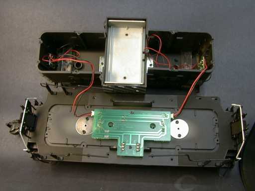 When
splayed open, the Center Cab reveals that there is little inside
the unit. A distribution board is mounted to the frame and the hood
wiring plugs in. There is no overt provision for a DCC decoder or a
command receiver, but since all the necessary wiring is accessible
on the top of the distribution board, it would be an easy job with
a knife to cut the appropriate traces to make the necessary
connections. There is quite a bit of room inside both hoods for
batteries, sound systems, and control receivers or decoders.
When
splayed open, the Center Cab reveals that there is little inside
the unit. A distribution board is mounted to the frame and the hood
wiring plugs in. There is no overt provision for a DCC decoder or a
command receiver, but since all the necessary wiring is accessible
on the top of the distribution board, it would be an easy job with
a knife to cut the appropriate traces to make the necessary
connections. There is quite a bit of room inside both hoods for
batteries, sound systems, and control receivers or decoders.
 The
schematic of the Center Cab is dead simple. The main distribution
board on the frame interconnects the motors and power pickups.
Lighting wires are taken off the board to go to each hood. The
lighting is the same as on recent RS-3's but it cannot be turned
off. There are incandescent lights for the cab and the number
boards. The headlights are yellow LED's. These can be seen in the
daylight, but do not cast any form of beam at night. There is a
"smoke" switch but no smoke unit to switch. The switch just
terminates on a pad on the circuit board.
The
schematic of the Center Cab is dead simple. The main distribution
board on the frame interconnects the motors and power pickups.
Lighting wires are taken off the board to go to each hood. The
lighting is the same as on recent RS-3's but it cannot be turned
off. There are incandescent lights for the cab and the number
boards. The headlights are yellow LED's. These can be seen in the
daylight, but do not cast any form of beam at night. There is a
"smoke" switch but no smoke unit to switch. The switch just
terminates on a pad on the circuit board.
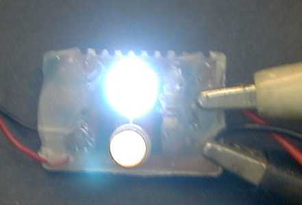 The two LEDs on
each end are wired in series with a 470 ohm current limiting
resistor. This sets the diode current at about 20 mA, just right
for a White LED. I have installed
one bright white LED in place of one of the stock LED's in this
picture. The white LED is so bright, that getting this picture was
difficult but it can be seen how much more intense the white LED is
in comparison to the wimpy stock yellow LED. As viewed by eye, the
difference is even greater than the photo indicates.
The two LEDs on
each end are wired in series with a 470 ohm current limiting
resistor. This sets the diode current at about 20 mA, just right
for a White LED. I have installed
one bright white LED in place of one of the stock LED's in this
picture. The white LED is so bright, that getting this picture was
difficult but it can be seen how much more intense the white LED is
in comparison to the wimpy stock yellow LED. As viewed by eye, the
difference is even greater than the photo indicates.
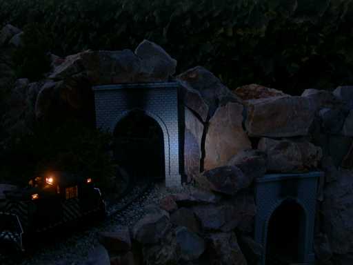 With the headlights modified, the Center
Cab will cast a non trivial beam in darkness. The intensity of the
light cannot compete with sunlight but if you run at night, it
makes a considerable improvement.
With the headlights modified, the Center
Cab will cast a non trivial beam in darkness. The intensity of the
light cannot compete with sunlight but if you run at night, it
makes a considerable improvement.
[ Top ]
Smoke
 The Center Cab
Switcher DOES NOT have smoke units, but it doesn't
appear that it would be difficult to install LGB smoke units. The
stack is nearly big enough to take one dropped in from the top. A
little work with a 3/8" drill bit and a rattail file can open the
stack sufficiently to allow an LGB or Seuthe smoke unit to fit. I
am not sure that I want to install $40+ worth of smoke units in
this inexpensive locomotive, but it could be done.
The Center Cab
Switcher DOES NOT have smoke units, but it doesn't
appear that it would be difficult to install LGB smoke units. The
stack is nearly big enough to take one dropped in from the top. A
little work with a 3/8" drill bit and a rattail file can open the
stack sufficiently to allow an LGB or Seuthe smoke unit to fit. I
am not sure that I want to install $40+ worth of smoke units in
this inexpensive locomotive, but it could be done.
[ Top ]
Disassembly of the Center Cab
While the Center Cab is not difficult to take apart, there sure
are a lot of screws that need to be removed to do it. Due to
interference between the sideframes and the hood and cab mounting
screws, it is easier overall to just bite the bullet and strip the
whole thing down short of removing the bricks. Remove all four
sideframes (2 screws each). Then remove 14 more screws underneath
to release the battery boxes, hoods and the cab. Both hoods and the
cab come off as a unit.
If you think that you might want to get into this loco more than
once, then when you reassemble it, leave out the hood screws that
are obscured by the truck sideframes. These aren't really necessary
to hold the hoods on because there are tabs in the battery boxes
that also secure the hoods.
[ Top ]
Radio Control Installation in the Center
Cab
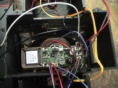
 I installed a new
Crest CRE-55491 On Board Train Engineer in the Center Cab. The
installation was pretty easy. Although the rewiring was fairly
extensive from a schematic point of view, it only took 8 circuit
board cuts. Six of the cuts are on the main board and one on each
headlight board. The cuts separate the main circuit board into 4
isolated sections, the power bus, the motor bus and one section
each for the front and rear headlights.
I installed a new
Crest CRE-55491 On Board Train Engineer in the Center Cab. The
installation was pretty easy. Although the rewiring was fairly
extensive from a schematic point of view, it only took 8 circuit
board cuts. Six of the cuts are on the main board and one on each
headlight board. The cuts separate the main circuit board into 4
isolated sections, the power bus, the motor bus and one section
each for the front and rear headlights.
In order to use just the four wires that already go between the
frame and the shell, the functions of the four wires were
reassigned. One brings power up to the shell. The other three
activate one each of the three lighting circuits, the front
headlights, the rear headlights and the cab/number board lights.
The power going to the shell is derived from the internal bus of
the 55491. This bus is available by tapping power from the positive
terminal of the 220 uF capacitor on the 55491.
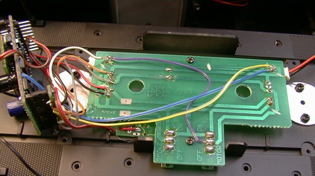 The cuts can be seen as
light marks on the board, two near each end and one in the upper
center that cuts through BOTH thin traces.
The cuts can be seen as
light marks on the board, two near each end and one in the upper
center that cuts through BOTH thin traces.
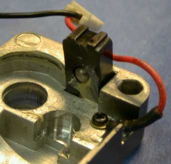
The code set switch is mounted to project through the frame
right right next to the switches. The 55491 itself is hot glued
sideways to the frame. The previous motor switch has been
reassigned to control the cab and number board wiring.
[ Top ]
Battery Power Installation in the Center
Cab
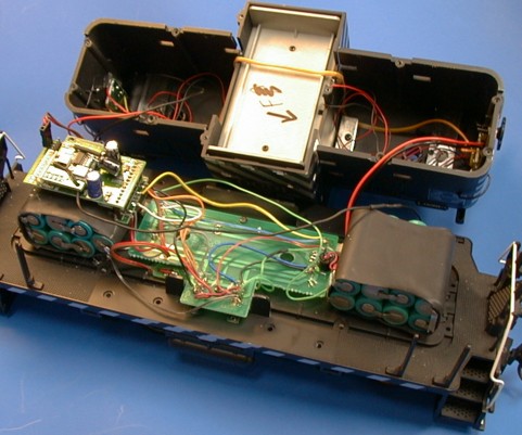 After the track
powered RC installation was in and working, I converted the loco to
track or battery powered operation. For this conversion, I selected
NiMH batteries. 15 AA cells were made into two packs, one of 7
cells and the other 8 cells. The packs were installed in both hoods
with foam mounting tape so that they cleared the truck pivots. The
55491 was mounted with hot glue on top of one of the packs. A
charging jack was mounted on the floor underneath the circuit
board.
After the track
powered RC installation was in and working, I converted the loco to
track or battery powered operation. For this conversion, I selected
NiMH batteries. 15 AA cells were made into two packs, one of 7
cells and the other 8 cells. The packs were installed in both hoods
with foam mounting tape so that they cleared the truck pivots. The
55491 was mounted with hot glue on top of one of the packs. A
charging jack was mounted on the floor underneath the circuit
board.
 For this
installation, I elected to use the "tri-modal" configuration. This
allows the loco to run from straight track power, track powered R/C
or battery powered R/C. Since two DPDT switches were already there,
this installation was pretty easy.
For this
installation, I elected to use the "tri-modal" configuration. This
allows the loco to run from straight track power, track powered R/C
or battery powered R/C. Since two DPDT switches were already there,
this installation was pretty easy.
I basically hacked most of the traces on the circuit board to
disconnect everything but the front and rear power pickups and the
motor connectors. All of the traces to the switches were cut and
replaced with wire. Note that the printed wiring board has both
sides of each switch paralleled on the circuit board. It is
necessary to wick all of the solder from the switch terminals and
then carve out the traces between the poles of the switches.
The schematic shows the general wiring of the tri-modal
configuration. One switch controls the source of power, and the
other switch controls where the motors get their power from. The
lighting wiring was left the same as it was in the track powered
R/C configuration. The circuit is designed to charge from 24
VDC.
The headlights are wired the same as the track powered RC
installation but I abandoned the marker and cab lights. These are
incandescent bulbs and draw too much current to run from batteries.
Also, I reused the switch for another purpose so I just left the
incandescent bulbs disconnected.
The antenna of the 75 MHz 55491 is about 18" long. It is routed
around the frame following the shell outline. In this
configuration, the R/C range is 10 to maybe 20 feet.
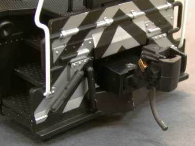
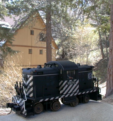 The range that I got with
the less than ideal antenna arrangement needed improvement. I had
tried other arrangements in the past with the antenna wire wound
around the top of the loco, but these were usually mechanically
unsatisfactory because they complicated disassembly of the loco.
This time I tried a whip antenna made from about 1 foot (30 cm) of
0.020" (0.5 mm) music wire. The wire is so thin that it is nearly
invisible past a few feet especially if it does not contrast with
the background. The wire can be seen coming up from the front deck
just at the nearest corner of the hood. It can also be seen
contrasted against the house in the background.
The range that I got with
the less than ideal antenna arrangement needed improvement. I had
tried other arrangements in the past with the antenna wire wound
around the top of the loco, but these were usually mechanically
unsatisfactory because they complicated disassembly of the loco.
This time I tried a whip antenna made from about 1 foot (30 cm) of
0.020" (0.5 mm) music wire. The wire is so thin that it is nearly
invisible past a few feet especially if it does not contrast with
the background. The wire can be seen coming up from the front deck
just at the nearest corner of the hood. It can also be seen
contrasted against the house in the background.
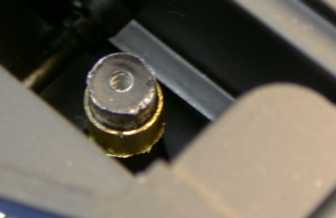
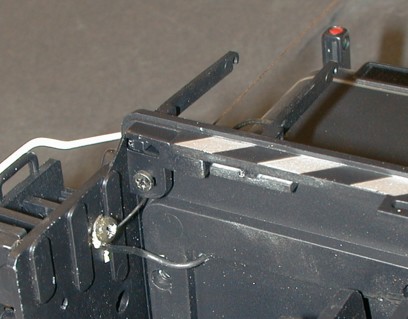 The wire
antenna was secured to the front pilot assembly with a self tapping
screw. The antenna wire comes through a 0.026" hole in the deck
just outside the cowl and is bent to fit around the screw head. The
antenna wire from the receiver comes though a small hole drilled in
the frame just inside the cowl and is also wrapped around the
screw.
The wire
antenna was secured to the front pilot assembly with a self tapping
screw. The antenna wire comes through a 0.026" hole in the deck
just outside the cowl and is bent to fit around the screw head. The
antenna wire from the receiver comes though a small hole drilled in
the frame just inside the cowl and is also wrapped around the
screw.
This arrangement yielded about triple the former range. There is
reliable control to 30' and some control to 50'. The wire is long
enough so that it will scrape low obstructions some, but it is
flexible enough so that it just slides underneath and pops back to
vertical after clearing the obstruction. Smaller music wire would
work as well, I happened to have the 0.020" diameter wire
handy.
It is somewhat ironic that in the years since I installed
battery/RC into the Center Cab, it get LESS runtime that it did
before. Since it is a 75 MHz RX, it doesn't integrate well with my
27 MHz trackside TE cab control system (except when switched to run
as an analog loco on the track) OR my DCC command control system.
To run it with the DCC stuff, I have to carry around the 75 MHz TX
in addition to the DCC throttle. Before I installed DCC compatible
controls for my interlocking route control system I had to carry
around a 27 MHz TE to control the routes, a DCC throttle to control
the loco and a 75 MHz TE to run the Center Cab. This was too
much.
Once I installed a DCC interface to the route control system, I
only had to carry the DCC throttle and I tended not to run the
Center Cab because it was not DCC capable. Then it occurred to me
that I could have it both ways....
[ Top ]
DCC Installation in the Center Cab
I recently ran the Center Cab at a train show for many hours.
The battery didn't go flat in about 2 hours of running, but I had
difficulty with radio range and also in setting a precision speed
so that the Center Cab stayed in speed sync with another track
powered train running on the same loop. The Train Engineer just
doesn't provide the precision speed control that DCC can provide. I
didn't run it often on the GIRR for the same reason. The loco
itself is very capable and, as demonstrated at the train show,
extremely tolerant of really bad track. All we could run
successfully were the smallest of locos. An FA, which is pretty
tolerant loco in itself, would derail in many places. We didn't
want to stop the show to diddle with the track so anything that had
troubles was simply set aside. The Center Cab ran for hours without
derailing at all.
I've worked out a method to leave virtually all the
functionality that I had with the loco before intact, but I can
still add DCC.
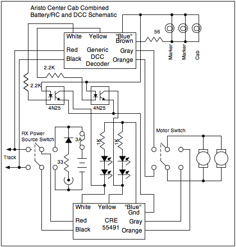 This is the scheme that I have
settled on. It is a slightly modified version of the tri-modal
configuration. The difference is the addition of DCC and the
removal of absolutely straight track power. To run on DC, the loco
depends on the DCC decoder to analog convert. The former "power"
switch now only switches power to the radio receiver so that it
isn't possible to run the motors straight from the battery as
before. The motor switch now selects between the output of the
radio receiver or the DCC decoder. The power selector switch also
serves to disconnect the battery to turn the loco "off" when in
storage or during charging.
This is the scheme that I have
settled on. It is a slightly modified version of the tri-modal
configuration. The difference is the addition of DCC and the
removal of absolutely straight track power. To run on DC, the loco
depends on the DCC decoder to analog convert. The former "power"
switch now only switches power to the radio receiver so that it
isn't possible to run the motors straight from the battery as
before. The motor switch now selects between the output of the
radio receiver or the DCC decoder. The power selector switch also
serves to disconnect the battery to turn the loco "off" when in
storage or during charging.
I had abandoned using the incandescent lighting with battery
power operation due to their current draw, but I will reconnect
those lamps to be controlled via a DCC function and powered only by
the DCC decoder. The CRE-55491 happily accepts DCC track power
although it totally ignores the DCC data on the track. Therefore
the power for the headlights still comes from the RX. It provides
the "Blue" wire function as it is either connected to the battery
or the track and it will see whatever power that is available so
that it can make the + Common voltage that is present on the "Blue"
wire. When the DCC decoder is inactive (because the loco is running
on battery power) the incandescent lights are off. The DCC decoder
can be programmed to enable whatever function is selected for the
cab/marker lights when analog converted so that these lights will
be either controllable with DCC or on if analog converted.
The headlight controls are wired in parallel via optical
isolators to both the DCC decoder and RX. When the loco comes to a
stop, the CRE-55491 turns the headlights off. As long as the
CRE-55491 is remembering that it's last speed command was to stop,
it won't mess with the lights when it isn't being used. Then the
DCC decoder can control the headlights. When switched to battery
power, the DCC decoder is inactive and it leaves the headlights
alone allowing the CRE-55491 to control them. To make this work, I
need to use the "ground" pin on the RX so that the power supplied
by the RX blue wire will return to the RX. There is a grounding
ambiguity without the optical isolators. If the RX is switched to
battery power and the loco is sitting on powered track, there is no
ground return for the headlights to the DCC decoder. Use of the
optical isolators will eliminate that issue.
I tried to fit an available MRC322 in there but it just wouldn't
fit. The MRC322 has a sort of a sound system but it just doesn't
analog convert very well at all. A QSI decoder would fit where the
TE RX is now and it has sound but to buy a new one and make it work
with the battery I'd need a GWire receiver and an Airwire
transmitter as well. This would total about $400 out of pocket, too
much. A DG583S would fit well but it doesn't have sound. A DSX
sound decoder doesn't have the volume for outdoor use. A Phoenix P5
would work, but it's pretty expensive too.
A Dallee system will
barely fit in addition to a DG583S. The Dallee will integrate well
in this configuration and will operate properly when either the DCC
decoder or RX is running the show. So, since I have a DG583S
already and a Dallee board would cost about $94, this looks like
the route I will take. The conversion to DCC costs nothing
additional out of pocket and adding sound costs $94 which I can
optionally do later.
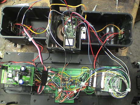
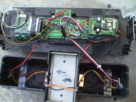 This is the Center Cab with
the DG583S installed. I followed the schematic shown above. Since I
am using the "blue" wires from BOTH the RX and decoder, I had to
add one wire going between the frame and shell. I actually added
three wires because that is what my swap meet special plug/socket
harnesses have and if I ever do add sound, I'll need the other two
wires for the speaker. I did find a place for a small speaker which
can mount in the "rear" hood facing into the cab. I'd have to drill
some holes in the "back" of the cab and take out some cab windows
to let the sound out, but it would work.
This is the Center Cab with
the DG583S installed. I followed the schematic shown above. Since I
am using the "blue" wires from BOTH the RX and decoder, I had to
add one wire going between the frame and shell. I actually added
three wires because that is what my swap meet special plug/socket
harnesses have and if I ever do add sound, I'll need the other two
wires for the speaker. I did find a place for a small speaker which
can mount in the "rear" hood facing into the cab. I'd have to drill
some holes in the "back" of the cab and take out some cab windows
to let the sound out, but it would work.
The two optical isolators are mounted "dead bug" fashion with
foam tape in the middle of the circuit board. They just fit
underneath the cab insert.
There was one ambiguity that I had to work out. This loco
doesn't have an FRA required marking to designate the "front."
Normally, there would be an "F" painted on the side of the frame at
the front of a loco. Diesels run happily either direction so that
the "front" is usually determined by the position of the control
stand. In the Center Cab, the only thing that isn't symmetrical is
the control stand in the cab. It's orientation determines the
front. In this installation, the RX is at the rear, the decoder at
the front. I have set the headlights to conform to these
conventions for both the decoder and the RX.
The analog conversion capability of this decoder is quite good
when running on straight DC track power. One would hardly know that
a DCC decoder is in the loop. However, the decoder doesn't like PWC
on the track at all. It will run, but it's throttle response is
poor and the loco is jerky at some speeds. This decoder can also
activate one set of functions to be on when analog converted. This
is done by programming CV13 as per the decoder programming
instruction book. I've set it to run the headlights directionally
and to turn on the cab lights.
[ Top ]
Sound Installation in the Center Cab
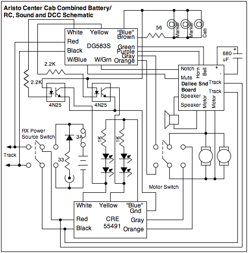 If I elect to install a
Dallee sound board, I would wire it like this. The Dallee board
needs an independent source of track power, it gets that from the
input to the RX which is powered one way or another. The motor
inputs to the Dallee are optically isolated on the Dallee board.
The trigger inputs won't have a ground return when the RX is
running on battery power, but the RX cannot command them anyway and
the decoder will be inactive so that it cannot command them either.
However the motor sound will run when the RX is running on battery
power.
If I elect to install a
Dallee sound board, I would wire it like this. The Dallee board
needs an independent source of track power, it gets that from the
input to the RX which is powered one way or another. The motor
inputs to the Dallee are optically isolated on the Dallee board.
The trigger inputs won't have a ground return when the RX is
running on battery power, but the RX cannot command them anyway and
the decoder will be inactive so that it cannot command them either.
However the motor sound will run when the RX is running on battery
power.
It took me awhile, but I eventually did install a Dallee #731
(44 ton) sound system in the Center Cab. I choose this particular
system because:
- It was fairly inexpensive ($95)
- Would integrate well in the dual motor controller system
- Sounds pretty good, much better than older Dallee systems
- The motor sound is good
- The single chime horn is excellent
- The bell is good
However, the installation didn't go as easily as I had hoped.
With all the other crap that was already there (battery, TE RX and
a DCC decoder) there wasn't room for the sound board under the
hoods or cab.
 While
testing the board on the bench, I also realized that it really
could use a good speaker and the speaker that I had planned to use
wasn't going to cut it. There was no place to install a better
speaker and no room for the board. Something had to give.
While
testing the board on the bench, I also realized that it really
could use a good speaker and the speaker that I had planned to use
wasn't going to cut it. There was no place to install a better
speaker and no room for the board. Something had to give.
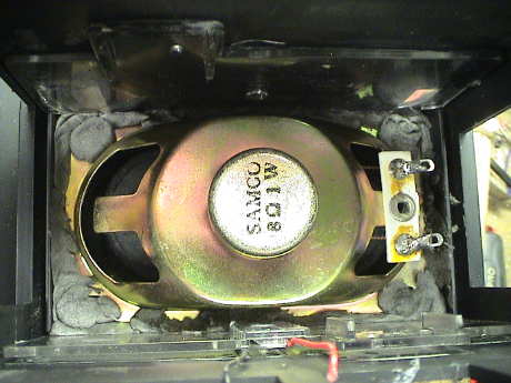
I elected to rip the cab interior out of the loco and use the
cab volume for the sound installation. The speaker is mounted
against the roof with epoxy putty sealing it in place. The
"enclosure" is now in front of the speaker and the sound is emitted
from the back of the speaker.
 I
removed the side windows (which I would have to have done anyway)
to let the sound out of the loco. Now the board can be easily seen
through the window openings, I'll probably jam some black paper in
there to hide the board a little. However, I can get to the volume
and speed controls on the board by working through the cab side
windows.
I
removed the side windows (which I would have to have done anyway)
to let the sound out of the loco. Now the board can be easily seen
through the window openings, I'll probably jam some black paper in
there to hide the board a little. However, I can get to the volume
and speed controls on the board by working through the cab side
windows.
 There
are a total of 12 wires that go to the Dallee board. There are two
track power wires, two motor wires (optically isolated on the
board), two wires going to a storage capacitor, two speaker wires
and four function wires. All these wires plug into the Dallee board
so that I didn't install a separate multipin connector. I can still
remove the shell entirely if I want.
There
are a total of 12 wires that go to the Dallee board. There are two
track power wires, two motor wires (optically isolated on the
board), two wires going to a storage capacitor, two speaker wires
and four function wires. All these wires plug into the Dallee board
so that I didn't install a separate multipin connector. I can still
remove the shell entirely if I want.
[ Top ] [ Home ] [ Up ] [
Previous Page ] [ Next Page ]
This page has been accessed  times since 12 July 00.
© 2000-2009 George Schreyer
Created July 12, 2000
Last Updated August 13, 2009
 25 Aug
08
25 Aug
08