 The Aristo FA-1 is a very good engine. It
has been made for many years and it is pretty bug free. Since it is
shorter than the U-25 and RS-3, it is actually usable on 2' radius
curves with a minor modification to increase the rear coupler
swing.
The Aristo FA-1 is a very good engine. It
has been made for many years and it is pretty bug free. Since it is
shorter than the U-25 and RS-3, it is actually usable on 2' radius
curves with a minor modification to increase the rear coupler
swing.The Aristo FA-1 is a very good engine. It
has been made for many years and it is pretty bug free. Since it is
shorter than the U-25 and RS-3, it is actually usable on 2' radius
curves with a minor modification to increase the rear coupler
swing.
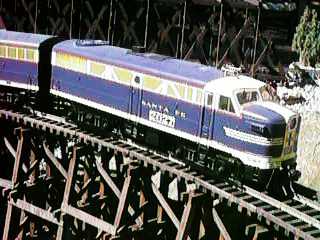
The Aristo FA-1/FB-1 is modeled after the Alco prototype which was first built in 1946. The FA used Alco's turbocharged 1500 hp 4 stroke diesel engine. Later models were upgraded to 1600 hp.
The model is nominally 1:29 scale and scales out pretty close. The model has fair detail and runs smoothly and quietly and it pulls well.
As of Oct 2000, I have managed to acquire 3 FA's and 2 FB's. One was built in the mid 90's and the others were purchased used and are even older. Judging by wheel wear, all are very high milers, but all run fine. Two of the oldest (ATSF freight) were left pretty much stock for a long time with just some added weight and power connectors to cross jump the power pickups. Eventually, these both got DCC decoders. The newest loco has been lowered and battery powered using an Aristo 5490 controller among other less serious hacks. It also got a DCC decoder in addition to the battery/RC equipment. The two Warbonnet locos have been lowered and have also been converted to DCC. The Warbonnet FA has also had a Soundtraxx Sierra sound system added.
 27 Sep 09 25 Aug 08 6 Nov 09 30 Oct 08 18 Feb 09
The FA itself will run on 2' radius track, but the rear coupler swing is limited and if you use knuckle couplers, the FA will drag the following car off the tracks in the turns. This is easy to fix.
 Open up the engine and file or
grind at the arc shaped groove that the rear coupler mount swings
in to allow to cover a wider arc. You will have to increase the
length of the arc by about 50%.
Open up the engine and file or
grind at the arc shaped groove that the rear coupler mount swings
in to allow to cover a wider arc. You will have to increase the
length of the arc by about 50%.
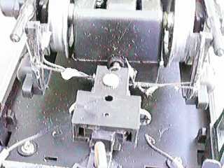
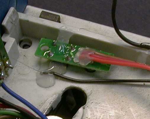
Once this is done, you'll have fixed derailment problems, but the coupler will not even get close to aligning to another car for coupling if the engine is even partly on a curve. I found that if a piece of thread is clamped under the coupler and then wrapped around the brake assembly at the rear of the back truck, the coupler will be swung sideways with the movement of the truck. You can see this in the photo. Since tying a knot in the thread is difficult, I instead secured it with a dab of hot glue.
 The front coupler on
the FA mounts on a plastic post. If you run an A-A, A-B-A, or
A-B-B-A set, you can pull a long string of cars and all that force
will be applied to that coupler post on the last engine.
The front coupler on
the FA mounts on a plastic post. If you run an A-A, A-B-A, or
A-B-B-A set, you can pull a long string of cars and all that force
will be applied to that coupler post on the last engine.
The mounting post is not up to the task of hauling heavy loads. It will flex badly. The fix is to wad some plumbers epoxy putty between the post and the pilot to prevent to post from flexing. Backing heavy loads can also be a problem, if the epoxy on the front of the post doesn't prevent the post from flexing the other direction, then make up a fillet of the stuff behind the post.
The swing of the front coupler of the FA is limited so that it will derail the following car on 2' radius track when run as the second engine of an A-A set. Both the stock coupler or the Kadee coupler will require mounting changes to allow wider swing of the coupler. I've not done this mod as my FA's now run on 4' minimum radius track but I suspect that the opening in the pilot will have to be widened and the centering spring will require changes or abandonment.
 There is also a
derailment issue with the front coupler of the FA pulling a car
with truck mounted couplers over turnouts in one particular track
geometry. This case is pretty obscure, but it happened to me twice
requiring some minor trackwork changes. If the rear FA of an A-A
set runs through the straight path facing point over an LGB 1600
turnout, AND the track curves away from the curved
path immediately following the turnout, a derailment will happen
nearly every time. As the second engine passes the turnout and
enters the following curve section, its front coupler (the one
pulling the train) swings the other way. This pushes the coupler on
the following car sideways just as the first wheel of the car is
running through the frog and the wheel will usually slip sideways
and hit the point of the frog dead on and derail. The only fix for
this problem is to add at least 6" of straight track (more is
better) between the turnout and the following curve. Actually, this
problem is not unique to the FA, it will happen on any loco with
body mounted couplers and limited coupler swing. The RS-3 will
actually do it worse as the engine is longer and the coupler is
mounted even further from the trucks.
There is also a
derailment issue with the front coupler of the FA pulling a car
with truck mounted couplers over turnouts in one particular track
geometry. This case is pretty obscure, but it happened to me twice
requiring some minor trackwork changes. If the rear FA of an A-A
set runs through the straight path facing point over an LGB 1600
turnout, AND the track curves away from the curved
path immediately following the turnout, a derailment will happen
nearly every time. As the second engine passes the turnout and
enters the following curve section, its front coupler (the one
pulling the train) swings the other way. This pushes the coupler on
the following car sideways just as the first wheel of the car is
running through the frog and the wheel will usually slip sideways
and hit the point of the frog dead on and derail. The only fix for
this problem is to add at least 6" of straight track (more is
better) between the turnout and the following curve. Actually, this
problem is not unique to the FA, it will happen on any loco with
body mounted couplers and limited coupler swing. The RS-3 will
actually do it worse as the engine is longer and the coupler is
mounted even further from the trucks.
If you mount Kadee's on the rear of an FA or either end of an FB, you may need to modify the swinging arm slightly. Many FA and FB units allow too much vertical play in the coupler swing arm. Under load, the coupler will tend to "dip" or drop down to its lowest position. This can cause the trip pin on the Kadee coupler to hit an uncoupling magnet or maybe part of a turnout. I found this out the hard way when a coupler literally snapped its pivot post out of the coupler body. To tighten up the slop in the swing arm, remove the shell and take the screw, washer and spring off the part of the offending swing arm that rides in the curved slot. Grind down the top 1/32" or so of the post and reattach the spring and washer and check the slop. Keep filing until the swing arm will not slop much vertically. If you file too much, the washer will pinch in the slot, in that case, just back the screw out a little. Apply some graphite to both sides of the slot and work it in until the swing arm moves freely. Then recheck the coupler height.
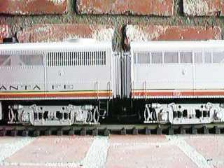
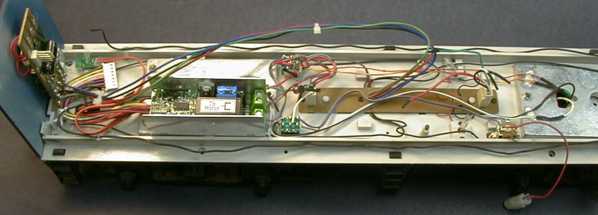
 In this photo you can see an extra pair
of wires leading from the loco body. These are power pickup jumpers
that I use to cross connect an FA-FB-FA set for 24 wheel power
pickup. The wires are the contacts from DB-25 computer connectors
covered with shrink tube. There is a male and female contact at
each end of the loco. These wires look a little like MU cables and
are generally unobtrusive. With power pickup on all 24 wheels, one
engine losing power temporarily does not cause the set to jerk and
the whole set will run smoothly on very dirty track. You can find
more information on how to make these cheap and easy contacts, see
Power Connector
Tips.
In this photo you can see an extra pair
of wires leading from the loco body. These are power pickup jumpers
that I use to cross connect an FA-FB-FA set for 24 wheel power
pickup. The wires are the contacts from DB-25 computer connectors
covered with shrink tube. There is a male and female contact at
each end of the loco. These wires look a little like MU cables and
are generally unobtrusive. With power pickup on all 24 wheels, one
engine losing power temporarily does not cause the set to jerk and
the whole set will run smoothly on very dirty track. You can find
more information on how to make these cheap and easy contacts, see
Power Connector
Tips.
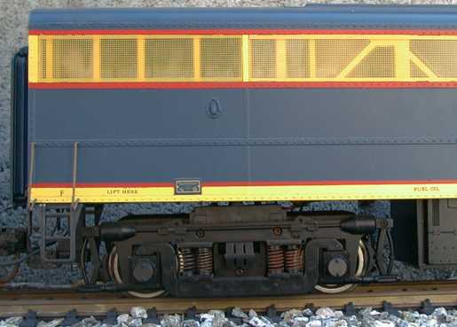
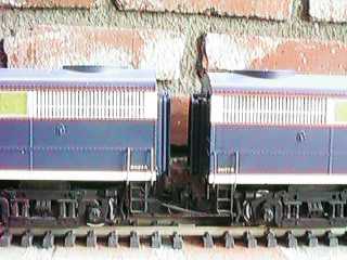 If you
mount Kadee's, you might want to modify the coupler mount a little
more to reduce the spacing between units. This photo shows the
spacing between the units with the standard Kadee kit mounted.
If you
mount Kadee's, you might want to modify the coupler mount a little
more to reduce the spacing between units. This photo shows the
spacing between the units with the standard Kadee kit mounted.
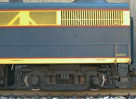
 By
mounting the coupler 1/4" further back, the diaphragm striker
plates will just touch when the engines are pressed together to
take all the slop out of the couplers. There will be less than 1/2"
gap with the couplers stretched out. The downside of this change is
that you have to uncouple the engines to get at the switches inside
the rear diaphragm.
By
mounting the coupler 1/4" further back, the diaphragm striker
plates will just touch when the engines are pressed together to
take all the slop out of the couplers. There will be less than 1/2"
gap with the couplers stretched out. The downside of this change is
that you have to uncouple the engines to get at the switches inside
the rear diaphragm.
 To remount the coupler,
use a razor saw to cut the last 1/4" off the coupler mount as
shown. Then drill a new hole in the coupler body 1/4" in front of
the existing hole. Remount the coupler body using the new hole in
the coupler body, the original screw and the original hole in the
mount.
To remount the coupler,
use a razor saw to cut the last 1/4" off the coupler mount as
shown. Then drill a new hole in the coupler body 1/4" in front of
the existing hole. Remount the coupler body using the new hole in
the coupler body, the original screw and the original hole in the
mount.
The FA is a little light and can use some weight. I usually add a total of 16 oz of lead fishing weights to the weights that are already installed above each truck. On the FA unit, be sure that the weight is thin enough to clear the floor of the cab.
Since this extra weight is carried by the wheel journals of the older style FA's, they will wear faster. Be sure to keep the wheel journals well lubricated. Newer models with ball bearing motor blocks will tolerate the extra weight without serious difficulty. Newer models do not have axle extensions that go into the sideframes.
[ Top ]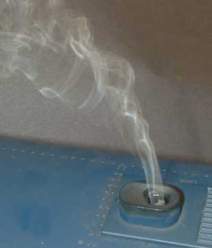 The smoke unit on the FA
typically does not generate a large volume of smoke, but it will
smoke for a long time. The generator can hold a large amount of
smoke fluid, 25 drops or more, which will allow it to generate
smoke for a half hour or more. Unlike LGB smoke units, adding a lot
of fluid does not slow the smoke generator down.
The smoke unit on the FA
typically does not generate a large volume of smoke, but it will
smoke for a long time. The generator can hold a large amount of
smoke fluid, 25 drops or more, which will allow it to generate
smoke for a half hour or more. Unlike LGB smoke units, adding a lot
of fluid does not slow the smoke generator down.
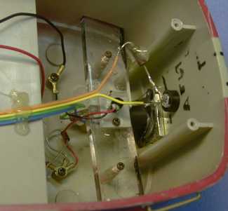
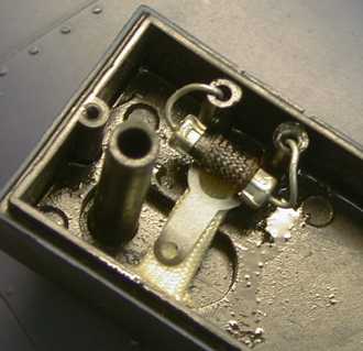 If your unit doesn't smoke for very long after
you add fluid, or if you have to add a lot of fluid to get it to
smoke at all, the wick is probably displaced and the fluid is just
sloshing around in the unit without getting to the heater. There is
a fiberglass wick that is supposed to rest in a small sump directly
below the smokestack but often it does not. There have been several
versions of the wick, but the problem is all the same, the wick
MUST rest in the fluid sump or the smoke unit will
not work properly. To fix it, remove the smoke unit and then remove
the smoke unit cover. Inspect the wick to and determine how to
rearrange it so that it sits in the sump. This unit has a metal
solder lug that captures the wick. The tab used be on the bottom so
that it didn't control the position of the wick. The heater element
was pulled out and flipped over so that the lug could be used to
hold the wick down. Older units don't have this lug so that the
wick must be massaged into place by looping it into the sump.
If your unit doesn't smoke for very long after
you add fluid, or if you have to add a lot of fluid to get it to
smoke at all, the wick is probably displaced and the fluid is just
sloshing around in the unit without getting to the heater. There is
a fiberglass wick that is supposed to rest in a small sump directly
below the smokestack but often it does not. There have been several
versions of the wick, but the problem is all the same, the wick
MUST rest in the fluid sump or the smoke unit will
not work properly. To fix it, remove the smoke unit and then remove
the smoke unit cover. Inspect the wick to and determine how to
rearrange it so that it sits in the sump. This unit has a metal
solder lug that captures the wick. The tab used be on the bottom so
that it didn't control the position of the wick. The heater element
was pulled out and flipped over so that the lug could be used to
hold the wick down. Older units don't have this lug so that the
wick must be massaged into place by looping it into the sump.
There is a fan which blows air down a small plastic tube which then blows air into the smoke unit. The air is directed to the top of the stack behind the stack opening so that the air must turn and circulate within the smoke unit. This turbulent air then blows smoke out of the smoke generator. The fan is wired in series with the smoke generator so that if the smoke generator isn't working, the fan won't run either. More information on the FA-1 smoke generator can be found at the Smoke Tips page.
 Jerry
McColgan writes: "I very recently bought 12 sets (24 locos) of the
Aristo B&O #22303 FA-1/FB-1's (with the new motor blocks and
traction tires). None of them has the opening for the fan forced
air to push the smoke out of the smoke unit. The fan works and the
tubing is in place, there is just no hole for the air to come out
of. It is very simple to fix - just pull up the smoke unit and, if
you look carefully, you can see where the hole should be. Drill the
hole with a 1/8" bit, replace the smoke unit and you are done."
Jerry
McColgan writes: "I very recently bought 12 sets (24 locos) of the
Aristo B&O #22303 FA-1/FB-1's (with the new motor blocks and
traction tires). None of them has the opening for the fan forced
air to push the smoke out of the smoke unit. The fan works and the
tubing is in place, there is just no hole for the air to come out
of. It is very simple to fix - just pull up the smoke unit and, if
you look carefully, you can see where the hole should be. Drill the
hole with a 1/8" bit, replace the smoke unit and you are done."
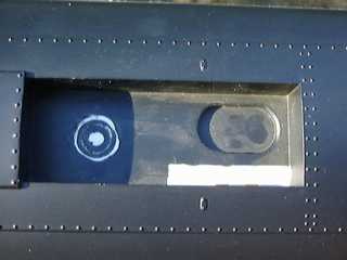
 This is the way
it is supposed to look on an older REA vintage FA.
This is the way
it is supposed to look on an older REA vintage FA.
A common cause of smoke generator problems is a bad connection between the smoke generator unit and the shell. Pull the smoke generator out of the shell and clean the contacts on the side of the smoke generator and the two spring contacts on the shell. Other points of contact problems can occur between the switch panel and the four contact fingers at rear of the fan assembly. If you suspect a problem here, pull out the switch panel and clean the contacts.
Sometimes the plastic tube that conducts air from the fan to the smoke unit will get kinked and the fan won't pump air to the smoke unit. The smoke will just drift out of the unit in a lazy plume instead of a directed stream as in the lead photo of this section. Someone wrote me a letter (which I apparently deleted so I cannot credit the author) suggesting that a kinked tube can be repaired by slipping some freight truck springs into the tube hold it open. This actually works.
The smoke switch is labeled "F", "Off", and "R." All the switch does is reverse the fan. I don't know why one would want to do this because the fan always runs the right direction with the switch in the "F" position (blowing air out of the smoke generator) no matter which direction the engine is traveling.
The fan makes a whining sound when running that changes pitch with engine speed. I suppose that you could call this noise "turbo whine" as the FA was a turbo charged locomotive. However, it gets really annoying. Someone, I've misplaced his note, wrote me to say that the whine is caused by an aerodynamic interaction between the fan blades and the grill. If the grill is removed the whine goes away. He said that he modified the fan to make it fit lower on the motor shaft. I found that it was easier to simply flip the fan blade assembly over and it does the same thing. Anyway, the fan still makes some noise, but the irritating whine is gone.
If you use Aristo PWC, the performance of the smoke unit can be improved at low engine speeds with the addition of one part. The upside is that the smoke unit will generate visible smoke before the engine starts to move and make good smoke at medium speeds. The dark side is that the fan will start running at nearly a constant speed before the engine starts (similar to the newer RS-3) and the whine (if you haven't fixed it already) can get annoying. Smoke generation at high speeds will not be improved.
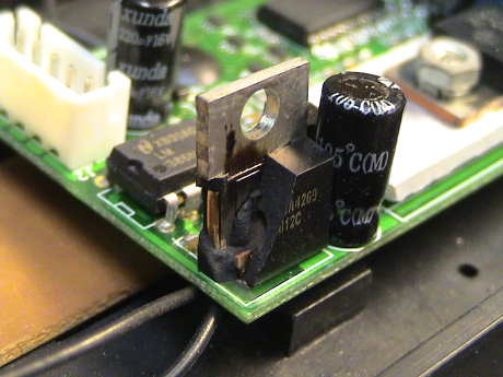
 The FA-1 smoke circuit looks
like this. The bridge rectifier and switch are on the switch board
at the rear of the locomotive. The resistors and the non-polarized
capacitor are mounted on a small board right under the fan
motor.
The FA-1 smoke circuit looks
like this. The bridge rectifier and switch are on the switch board
at the rear of the locomotive. The resistors and the non-polarized
capacitor are mounted on a small board right under the fan
motor.
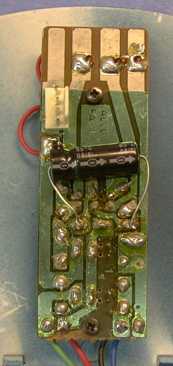
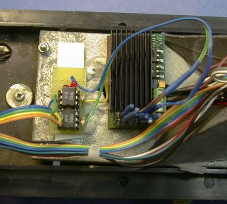
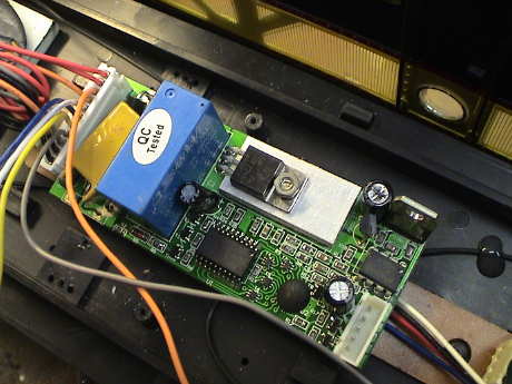
 This is a
partial diagram of the switch board at the back of a 1st generation
(gray box) locomotive. The new part is a capacitor which is wired
across the bridge rectifier. Solder it to the pads as shown. The
capacitor charges up on the peaks of PWC signal and discharges into
the smoke unit between pulses. A more complete description of what
happens can be found at PWC
Tips.
This is a
partial diagram of the switch board at the back of a 1st generation
(gray box) locomotive. The new part is a capacitor which is wired
across the bridge rectifier. Solder it to the pads as shown. The
capacitor charges up on the peaks of PWC signal and discharges into
the smoke unit between pulses. A more complete description of what
happens can be found at PWC
Tips.
 Another 2nd generation (black box) FA has a different board. The
spring contacts on the shell has been replaced with a wiring
harness and a connector. The board layout is different, but the
schematic is the same. The capacitor wires in the same place,
across the output of the bridge rectifier.
Another 2nd generation (black box) FA has a different board. The
spring contacts on the shell has been replaced with a wiring
harness and a connector. The board layout is different, but the
schematic is the same. The capacitor wires in the same place,
across the output of the bridge rectifier.
With PWC, the headlight intensity at low to mid speed can be improved by adding a capacitor to the headlight circuit similar to the modified circuit in the RS-3. Since the FA already uses an incandescent lamp and already has a diode, all that is needed is a 50 microfarad capacitor. Wrap the negative lead under the screw that holds black wires (engineer's side) and solder the positive lead to the junction of the diode and the headlamp. This area can be accessed by removing four screws under the front pilot assembly.
[ Top ]Once upon a time, Aristo marketed an analog sound system for the FA. It was discontinued, with some justification, after the newer and much better digital sound systems became available. I happened to come into the possession of one of these puppies so I know a little about it.
The analog system is fully contained in the fuel tank under the engine. It derives its power from two metal contact springs that contact metal pads on the underside of the engine. These pads are wired to the motor circuit of the FA so that the motors must be on to use the sound or charge its internal battery.
The quality of the sound produced by this system is marginal at best. At low speeds, there is an identifiable bell sound. As the speed increases, the bell mutes and the diesel prime mover sound ramps up in pitch. The prime mover sound is only a very rough approximation of the sound that a real diesel makes. At random times, a single chime type horn blows.
The power switch on the side has three positions, off in the center, engine only on one side and engine with horn on the other. At least its possible to turn the horn off.
The bell sound works with linear track power only. With PWC it gets fooled into thinking that the engine is going faster than it really is and the bell is never heard. This is actually a good thing.
[ Top ]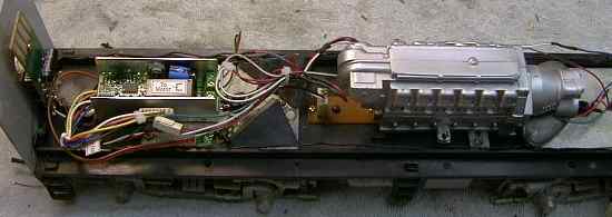
Installation of an ART-5490 Train Engineer on board mini receiver is fairly straightforward. The easiest method is to cut the wires leading to the motors and wire the motors in parallel and then connect the paralleled motors to the motor output of the ART-5490. One pair of the remaining wires that used to lead to a motor are insulated. The other set are used to provide power to the 5490. This same wiring can also be used for a DCC decoder.
The 5490 antenna wire is a little problematic. For best reception, the wire should be routed as high up as possible. However, then the wire would be attached to the shell and the receiver would be mounted to the frame. This makes separation of the frame and shell difficult. Instead, I used hot glue to attach the wire to the plastic ridge around the frame. It seemed to work ok.
A better method of routing the antenna wire would be to cut it a few inches from the 5490 and install a single pin connector so that the balance of the wire could be hot glued inside the top of the shell and still be easy to disconnect from the 5490 on the frame.
The headlight needs a little modification. With DC track power, the formally directional headlight might be on or off depending on how the engine is sitting on the track. The headlight state would have no bearing on the actual direction of travel of the engine. With DCC track power, the headlight would run at half intensity. In either case, simply shorting out the diode in series with the headlight will cause it to come on to full intensity all the time. With a DCC decoder, the headlight could be rewired to the F0 function output of the decoder to allow automatic directionality. With the 5490, it could be wired to an ART-5495 accessory controller adaptor, but it would have to be turned on or off manually. The headlight could also be rewired to the motor output of the 5490 and if the diode was retained, it would be directional, but it would not be constant intensity. Eventually I wired the headlight to the directional lighting outputs of a Soundtraxx Sierra sound system on one FA.
[ Top ]Soundtraxx has finally released their diesel versions of the Sierra. I purchased an Alco system with a Leslie 3 chime horn for installation in an Aristo FA. While testing on the bench, the system seemed to work fine, except for the automatic grade crossing horn signal. It would appear that the programming of the lengths of the horn blasts are incorrect for the Leslie horn version. The third "short" horn blast is imperceptibly shorter than the other three blasts. This didn't bother me much after I figured out what it was because I intended to control the horn manually with an ART-5495 accessory board attached to the ART-5490 mini receiver. Soundtraxx has corrected this problem so if your horn doesn't work correctly, write them and ask for a revised ROM.
The sound quality of the Sierra diesel system is pretty good. I've heard better, but only for significantly more money. Like most Sierra's, the volume has to be run up from the lowest settings or there will be some distortion. The diesel Sierra is programmable like the steam versions allowing settings that set automatic, triggered or manual control of most sound functions.
The lighting outputs are different from the steam version though. Each of the two 6 volt lighting outputs can be programmed for a steady or reversing headlight, a Mars light, a Gyralite, an oscillating headlight, a single or double flash strobe, a rotary beacon, a Prime Stratolite, type 1 or 2 ditch lights, a FRED or a flickering engine exhaust (for those engines that throw sparks). When a light is programmed as a reversing headlight, the engine must stop and stand for a few seconds to activate the reversed function. If not, the headlight may not come on or go off as it is supposed to. I wired the two lighting functions to white LEDs as described in the next section.
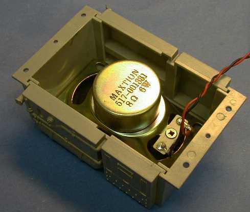 As with any Sierra installation, I don't use the
Sierra speaker. In this case, I had to use another speaker because
a speaker was not included. Sierra sells this unit for installation
in an RS-3 which already has a speaker. In any event, my swap meet
speaker just fit in the fuel tank. This speaker is similar to the
RS-3 upgrade speaker that can be purchased from Aristo. New FA's
come with the tank predrilled for a speaker. My very old unit was
not drilled, but this is no big deal. The bottom of the tank can be
easily drilled and the speaker is held in place with hot glue. The
speaker wires are routed up through a small hole drilled in the
locomotive floor.
As with any Sierra installation, I don't use the
Sierra speaker. In this case, I had to use another speaker because
a speaker was not included. Sierra sells this unit for installation
in an RS-3 which already has a speaker. In any event, my swap meet
speaker just fit in the fuel tank. This speaker is similar to the
RS-3 upgrade speaker that can be purchased from Aristo. New FA's
come with the tank predrilled for a speaker. My very old unit was
not drilled, but this is no big deal. The bottom of the tank can be
easily drilled and the speaker is held in place with hot glue. The
speaker wires are routed up through a small hole drilled in the
locomotive floor.
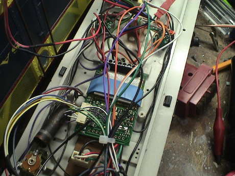
 Since its
hard to see the "engine" inside the carbody anyway, I removed it to
make more room for the sound system installation. The Sierra needs
some interface circuitry to work with a 5490 onboard RX. That
circuitry is mounted on the perforated board next to the Sierra.
The battery is not really needed for this installation, but I
installed it anyway. The sound system power switch and the external
programming switch are mounted in the frame immediately forward of
the battery.
Since its
hard to see the "engine" inside the carbody anyway, I removed it to
make more room for the sound system installation. The Sierra needs
some interface circuitry to work with a 5490 onboard RX. That
circuitry is mounted on the perforated board next to the Sierra.
The battery is not really needed for this installation, but I
installed it anyway. The sound system power switch and the external
programming switch are mounted in the frame immediately forward of
the battery.
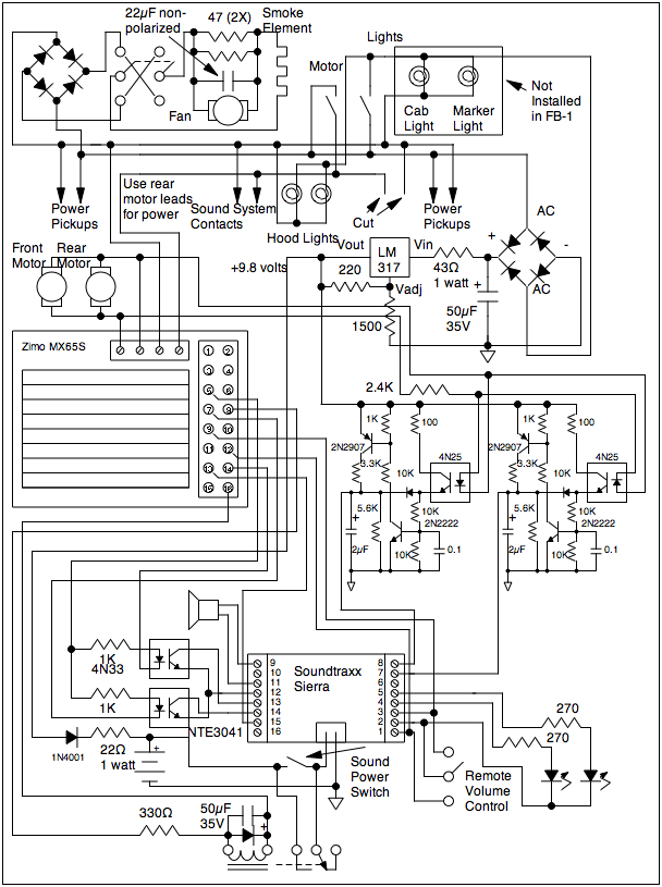
The schematic of this
installation in the FA is fairly complicated. Power for the battery
charger circuit is taken off the lighting circuit so that it can be
shut off if desired. The proper traces are shown in the diagram
(carbody lights and common). The circuit includes a 9 volt
regulator to allow the battery to charge from track power (DC, PWC
or DCC). There are also two optical isolators that are used to
allow the Sierra to work from the 5490 motor output as described in
the Soundtraxx Sierra Technical Note #6. However, this circuit
didn't work properly with this diesel system. I had used this
technique on the Bachmann Shay and Climax and it worked fine.
However, for those systems, all it needs to detect is the polarity
of the motor drive and be able to detect small motor voltages to
control the automatic whistle signals and the automatic bell.
The problem is that this circuit can't pull the voltage at pin 7 or pin 8 high enough to cause the diesel sound to rev past notch 1. Pin 7 gets pulled high when in reverse, pin 8 when going forward. Normally, the collectors of the optoisolators are connected to pin 4 on the Sierra. This is the internal Sierra positive bus. There isn't enough voltage here to pull the sense voltage high enough to cause the system to rev up. The a patch around this problem is to use the 9 volt output from the regulator as a voltage source for the optoisolator transistors so that they can pull the sense voltage to the 5.2 volts required to reach notch 8. At input voltages past 7 volts, the Sierra starts to draw serious current from the sense pins (7 or 8) so that the optoisolator couldn't source it if it tried. The 100 ohm resistor in the collectors of the optoisolators is there to limit the current to safe values in case the Sierra does start to draw high current on the sense pins. The sense current below 6 volts is about 10 mA. The 2 uF capacitors help boost the average voltage a little on the sense pins to allow the sound system to rev up better at lower motor speeds.
The system still doesn't ramp up real well, especially at the lower notches. Adding the 2.7K resistors biases up the control voltage terminals to about 2.25 volts all the time so that the sound system reaches the lower notches at lower speeds. However, since the voltage at pins 7 and 8 now never go to zero, the sound system doesn't know when the engine has stopped, therefore it cannot blow the automatic whistle signals, nor detect if the engine has reversed. Also, without this detection method, the sound system has no way to tell when to activate the reversing headlight.
It would appear that the diesel Sierra and the ART-5490 are not an ideally suited pair. Some DCC decoders work the same way and some additional interface circuitry is needed to get the Sierra to work correctly with them. I didn't finish the development of the improved interface until I had already pulled the 5490's out (to use elsewhere). However, the interface circuitry described in the DCC conversion section below ought to work properly with a 5490 as well.
For reference, the following table lists the input voltages required to reach the 8 discrete throttle notches when the Sierra is programmed for its most sensitive setting (Register #2 set to 25%). Lower sensitivity settings might be needed for use with regular track power, but at lower sensitivity the system won't budge off idle when run from the optoisolator source.
An Alco 244 diesel engine has a funny governor. When the engine speed needs to be reduced, it cuts off the fuel for a short time, so at low load the engine kind of burps along. The Sierra does this too so don't be surprised when it seems to regularly cut out.
Also don't be surprised by the clanky sound of the Alco system. Alco engines, even ones in perfect condition, tend to sound like they have a serious rod knock all the time.
| Throttle Notch |
Input Voltage Range | Engine Sound | |
|---|---|---|---|
| Min | Max | ||
| Idle | 0 | 2.3 | Slow clanky idle |
| 1 | 2.3 | 2.7 | Slow Burble |
| 2 | 2.7 | 3.3 | Faster Burble |
| 3 | 3.3 | 3.7 | Run-Pause |
| 4 | 3.2 | 3.4 | Steady Slow Run |
| 5 | 3.7 | 4.2 | Faster Run |
| 6 | 4.2 | 4.8 | Faster Run |
| 7 | 4.8 | 5.2 | Faster Run |
| 8 | 5.2 | 18 | Fastest Run |
After nearly 5 years without a wheel turn, I fired the passenger FA set back up. Besides totally crudded up wheels, they ran fine. However, as expected, the Sierra sound system battery was dead. I replaced the supplied gelcell battery with a 5 AA NiMH cell battery and the sound system came back to life too.
[ Top ] I had
all the stuff I needed laying around, so I decided to convert an FA
to battery power. I choose this locomotive because the shell was
big enough to hold three 3 Ah gel cell batteries and an Aristo
5490. Since this was my first battery power conversion, I elected
to wire the loco in a "tri-modal" fashion. There are two switches
on the bottom that allow the engine to be converted from straight
track power, to constant track power command control and to battery
power command control. There is also a fourth possible combination,
straight battery power without a controller but this wouldn't be
too useful as the engine would just tear down the track out of
control. One of the switches selects the source of power, either
track or battery is connected to the internal power bus. The other
selects if the motors are wired to the output of the 5490 receiver,
or to the internal power bus. The other locomotive accessories are
still connected to the internal power bus so that they can be
turned on or off as desired by their original switches and will run
from whatever power source is selected.
I had
all the stuff I needed laying around, so I decided to convert an FA
to battery power. I choose this locomotive because the shell was
big enough to hold three 3 Ah gel cell batteries and an Aristo
5490. Since this was my first battery power conversion, I elected
to wire the loco in a "tri-modal" fashion. There are two switches
on the bottom that allow the engine to be converted from straight
track power, to constant track power command control and to battery
power command control. There is also a fourth possible combination,
straight battery power without a controller but this wouldn't be
too useful as the engine would just tear down the track out of
control. One of the switches selects the source of power, either
track or battery is connected to the internal power bus. The other
selects if the motors are wired to the output of the 5490 receiver,
or to the internal power bus. The other locomotive accessories are
still connected to the internal power bus so that they can be
turned on or off as desired by their original switches and will run
from whatever power source is selected.
This loco had an Aristo analog sound system. It would normally be connected to the motor bus, but since I disconnected the motors from the original motor connections, I rewired the sound system to reconnect to the motors. Then later I ripped it out and replaced it with and empty battery box. It never worked very well to begin with and it's battery died. I deemed it not worth fixing.
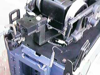
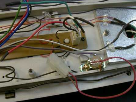
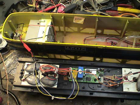
 This is a view of the frame of
the FA after it has been rewired for battery power with the 5490.
The antenna for the 5490 is wrapped around the edge of the frame.
To make room for the batteries, the original "engine" has been
removed.
This is a view of the frame of
the FA after it has been rewired for battery power with the 5490.
The antenna for the 5490 is wrapped around the edge of the frame.
To make room for the batteries, the original "engine" has been
removed.
 The
batteries themselves are mounted to the shell with adhesive. After
this picture was taken, they were wired in series to a two pin
Molex connector. Another mating connector is wired on the battery
charging jack. There is just enough room for the 5490 in the rear.
I am uncertain if the imbalance in weight will be a problem. If it
is, I'll ballast the spot without a battery with some fishing
weights to bring the shell back into balance.
The
batteries themselves are mounted to the shell with adhesive. After
this picture was taken, they were wired in series to a two pin
Molex connector. Another mating connector is wired on the battery
charging jack. There is just enough room for the 5490 in the rear.
I am uncertain if the imbalance in weight will be a problem. If it
is, I'll ballast the spot without a battery with some fishing
weights to bring the shell back into balance.
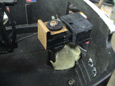
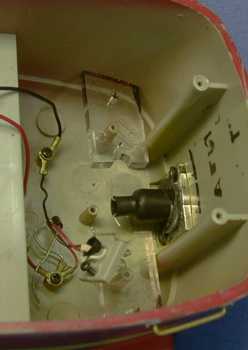
 The code set
button for the 5490 is mounted so that it projects through the
floor of the FA. It is held in place with a glob of hot glue.
The code set
button for the 5490 is mounted so that it projects through the
floor of the FA. It is held in place with a glob of hot glue.
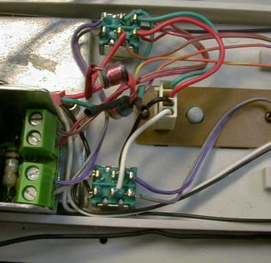 Two DPDT switches
are used to route power to set the operating mode for the
conversion. The lower switch selects the source of power. The
original power pickup wires (black and white in this loco) were cut
before they entered the distribution board in the middle of the
frame. They were then wired in parallel and connected to a pair of
end terminals on the switch. Note that the wire colors aren't
matched. Since the front and rear trucks are arranged backwards
with respect to each other, the wires have to "cross." Note that
this applies to the motor wires also. The other end contacts on the
switch go off to the charging jack and battery. The center
terminals wire back to the distribution board with the stubs of the
old rear power pickup wires.
Two DPDT switches
are used to route power to set the operating mode for the
conversion. The lower switch selects the source of power. The
original power pickup wires (black and white in this loco) were cut
before they entered the distribution board in the middle of the
frame. They were then wired in parallel and connected to a pair of
end terminals on the switch. Note that the wire colors aren't
matched. Since the front and rear trucks are arranged backwards
with respect to each other, the wires have to "cross." Note that
this applies to the motor wires also. The other end contacts on the
switch go off to the charging jack and battery. The center
terminals wire back to the distribution board with the stubs of the
old rear power pickup wires.
The upper switch selects the source of motor power. The motor wires (red and green in this loco) were cut and the motors were wired in parallel with the colors crossed. These were connected to the center terminals on the switch. The red and green wires that used to go to the rear motor were connected to one set of end terminals. The power input to the 5490 was also wired to these terminals. The other set of end terminals were then connected to the motor terminals of the 5490.
The sound contacts were insulated from the distribution board by gluing a thin piece of styrene to the bottom side of the distribution board to cover the contact patches. A pair of wires were then soldered to the sound system contact terminals and brought back into the loco body and connected to the motors. This is done so that the sound system can detect motor voltage in all modes.
 A battery charging
jack was installed in the frame to allow the batteries to be
recharged with an external charger. This particular jack is an
auto-disconnect type but it really isn't necessary to use one with
auto-disconnect. A current limiting resistor and diode have been
installed as well to allow the loco to be charged from a 24 VDS
source. When the loco is taken in from the layout, the power source
switch should be flipped to track power. This disconnects the
battery to keep it from being flattened while the loco is not in
use and it also disconnects the battery and charge jack so that the
battery can be recharged without powering any of the rest of the
loco.
A battery charging
jack was installed in the frame to allow the batteries to be
recharged with an external charger. This particular jack is an
auto-disconnect type but it really isn't necessary to use one with
auto-disconnect. A current limiting resistor and diode have been
installed as well to allow the loco to be charged from a 24 VDS
source. When the loco is taken in from the layout, the power source
switch should be flipped to track power. This disconnects the
battery to keep it from being flattened while the loco is not in
use and it also disconnects the battery and charge jack so that the
battery can be recharged without powering any of the rest of the
loco.
Note that all of the wires that come out of the front connector on the distribution board and cut and insulated.
With the stock lighting on, the converted engine pulled a five heavy cars at about 40 smph for 2 hours and 10 minutes before it slowed noticeably. The motors were hot and the 5490 was warm at the end of the run. I guess that this could be considered a good run time considering the heavy mechanical and electrical load. I also had the 5490 wired "backwards" so that the reversing relay was picked up for an extra 50 mA. The lights draw 42 mA each so the excess load was 260 mA. If the lights were off and the 5490 wired correctly, the run time would have been 15 minutes or so longer.
After the test run, I made some changes. The engine compartment lamps don't do much now except light up the bottoms of the batteries so I clipped them out of the circuit. I also removed the cab light, the number board light and the headlight and replaced them with LEDs. The cab is illuminated with a diffused lens yellow LED hot glued to the roof of the cab area. This was an LED removed from an Aristo Center Cab Switcher. The Critter and RS-3 use the same LED. The yellow LED light in the cab is very convincing in comparison to the hard blue-white light of the ultra-bright white LED headlight. The three LEDs are wired in series so that the same 20 mA gets used three times. The total voltage drop of the 3 LEDs is about 8 volts so a 500 ohm current limiting resistor sets the current to just 20 mA when running off the battery.
The lights could be wired off the existing lighting circuit but they would work differently depending on what kind of power is used. From regular track power they would be directional but not constant intensity. When running from the battery they would always be on at full intensity. From constant DC track power they might be on or off. From DCC track power they would be at half intensity all the time.
Instead, I wired them to the output of the bridge rectifier that powers the smoke circuit. They will be on at full intensity in all modes except regular track power. If PWC was used, they would be nearly constant intensity if the engine is moving at all. I hacked the circuit board to isolate the contacts of the light switch and wired the switch in series with the lights so that they could be turned off manually but even a 20 mA static load is not going to put a serious load on the battery so this is not a problem. They do go off when the power source switch set to track power so that the engine can be turned completely off so the batteries won't flatten in storage.
After I had done a combined battery/RC and DCC installation in an Aristo Center Cab I elected to do something similar to another battery/RC loco, a black box FA. These two locos were candidates for conversion back to DCC because they used to run well on track power. I converted them to battery/RC initially to just to experience what battery/RC does for my operations. After several years, I determined the answer.... not much. These locos were actually more of a hassle to use than the DCC locos because they used a different throttle than all the rest of them and I was carrying around too many throttles. However, the battery powered operations were an advantage sometimes, especially when I go visiting to somebody else's layout that doesn't have track power. Also, if my track was really dirty, the FA could pull a track cleaning car. However an DCC equipped SD45 does just well on absolutely cruddy track and if the track is really that bad, I can spend 5 minutes with a pole sander and clean it very well.
The other two battery/RC conversions, Thomas and an LGB 2060 do not have sufficient power pickup capability to run on dirty track. This is what drove the conversion to battery/RC in these locos and is also what makes it unreasonable to convert them back to be DCC compatible. However, in the intervening years, I've converted both of them back to DCC as well. They still have the battery/RC stuff but with the newer decoders, these locos now run fine on moderately clean track.
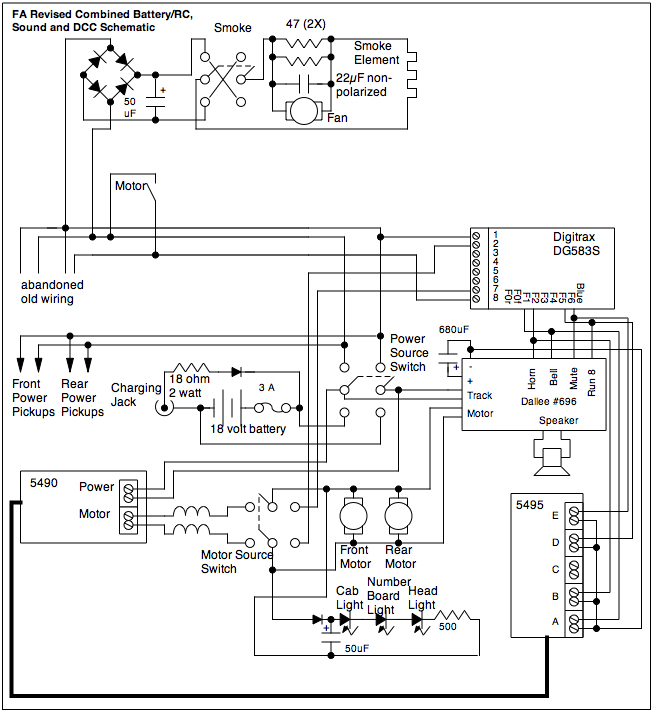
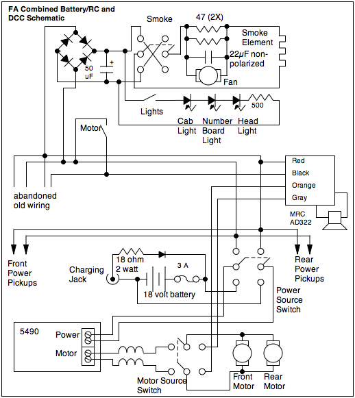 This is the revised schematic of
the battery/RC plus DCC FA. This schematic incorporates the
lighting changes that I had made since the original battery/RC
installation.
This is the revised schematic of
the battery/RC plus DCC FA. This schematic incorporates the
lighting changes that I had made since the original battery/RC
installation.
The MRC AD322 DCC decoder has sound, although it is not particularly good. In fact, it is downright terrible. The sound only operates when on DCC powered track. When I rewired the switches, the lighting is only connected to the track powered side. When the loco is run from the battery, there are no lights. Due to limitations of the 5490, it is not particularly easy to get the lights to run from the receiver unless I wire them back to the motor circuit which I elected not to do at this time.
The switching works a little different than before. The motor
switch selects between the RX and the DCC decoder. There is no
option for straight track power. The MRC AD322 DCC decoder analog
converts very poorly so I have disabled that function. The power
source switch determines where the RX gets it's power from, either
the track or the battery. The RX will still operate in the track
powered radio control mode with DC, DCC or PWC on the track.
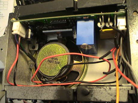 The inside of the
loco doesn't look a lot different than before. The new DCC stuff
has all gone into the fuel tank. The MRC supplied speaker is hot
glued to the floor with a piece of cardboard (cut from the decoder
box) covering the extra holes in the bottom of the tank. There is
another piece of cardboard insulating the speaker frame from the
decoder. Even though nothing appeared to be touching the frame, a
small piece of insulation is not a bad deal. The decoder itself is
held in place with a couple of dabs of hot glue.
The inside of the
loco doesn't look a lot different than before. The new DCC stuff
has all gone into the fuel tank. The MRC supplied speaker is hot
glued to the floor with a piece of cardboard (cut from the decoder
box) covering the extra holes in the bottom of the tank. There is
another piece of cardboard insulating the speaker frame from the
decoder. Even though nothing appeared to be touching the frame, a
small piece of insulation is not a bad deal. The decoder itself is
held in place with a couple of dabs of hot glue.
The installation works as well as the AD322 allows. The sound is marginal and the switching noise from the decoder can be heard when the loco runs. RC operations are the same as before, except currently without lights. However, I can now run my two freight FA's and an FB as an A-B-A set again.
 While the AD322 actually
worked in this installation after analog conversion was turned off,
"sound" that it made got on my nerves. This particular loco
originally had an Aristo analog sound module installed, it was
awful. The AD322 is better, but not by a lot. While running these
locos triple headed as an ABA set, the ran fine but I usually
turned the sound off. Further, this one didn't have sound at all
when running on battery power. The way I had wired it, it didn't
have lights either when running from the battery.
While the AD322 actually
worked in this installation after analog conversion was turned off,
"sound" that it made got on my nerves. This particular loco
originally had an Aristo analog sound module installed, it was
awful. The AD322 is better, but not by a lot. While running these
locos triple headed as an ABA set, the ran fine but I usually
turned the sound off. Further, this one didn't have sound at all
when running on battery power. The way I had wired it, it didn't
have lights either when running from the battery.
I elected to rearrange the wiring along the lines of what I did in the LGB 2060 conversion. I had another ART-5495 relay board and a Digitrax DG583S decoder. I ordered a Dallee #696 sound board with a single chime horn (the multiple chime Dallee horns are not so good) and planned out the installation. The major part of the wiring will remain the same but the AD322 will be changed out for DG583S/Dallee combo. This will allow sound while running on battery power AND the DCC decoder will be MUCH more reliable. I also elected to move the combined headlight/marker/cab lighting circuit which had already been converted to LEDs to the motor circuit so that they would be directional and work on battery power as well.
The Dallee board doesn't have the highest quality sound, but it is in the "good enough" category and it is relatively inexpensive at $94 including shipping from DCC Roundhouse. I will also upgrade the speaker to a larger oval version that fits well in the FA fuel tank.
As of Nov 6, 2009, the conversion is completed. It all worked as planned. The only change was that I abandonded the light switch so that there is no way to turn the lights off. Everything works as planned.
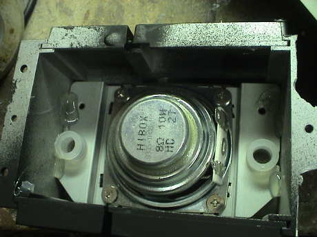 I pulled
the MRC AD322 and speaker from the fuel tank and substituted a
better speaker. This is one of the ones I got at a swap meet
integrated into automotive like plastic shell. The metal frame that
the speaker comes with is an exact fit into the Aristo fuel tank. A
little hot glue holds the bracket down which presses a foam gasket
on the front of the speaker down to the bottom of the tank.
I pulled
the MRC AD322 and speaker from the fuel tank and substituted a
better speaker. This is one of the ones I got at a swap meet
integrated into automotive like plastic shell. The metal frame that
the speaker comes with is an exact fit into the Aristo fuel tank. A
little hot glue holds the bracket down which presses a foam gasket
on the front of the speaker down to the bottom of the tank.
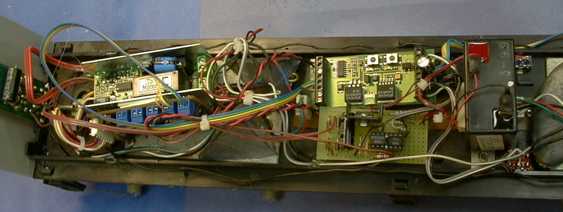
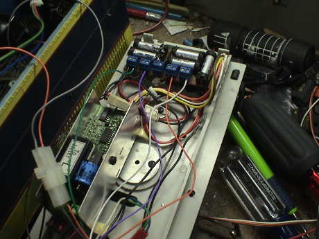
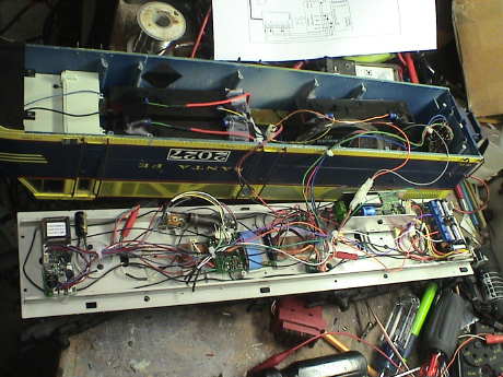 There
sure are lots of wires in there. As big as the FA is inside, I had
trouble locating places to mount the three new boards. The inside
of the shell is pretty well consumed by batteries so I had to mount
the boards down on the frame. The Dallee and 5495 could not stick
to the side of the 5490 as in the LGB 2060 installation.
There
sure are lots of wires in there. As big as the FA is inside, I had
trouble locating places to mount the three new boards. The inside
of the shell is pretty well consumed by batteries so I had to mount
the boards down on the frame. The Dallee and 5495 could not stick
to the side of the 5490 as in the LGB 2060 installation.
 The
Dallee board is mounted across the frame below the cab with some
hot glue. There was just enough room for it.
The
Dallee board is mounted across the frame below the cab with some
hot glue. There was just enough room for it.
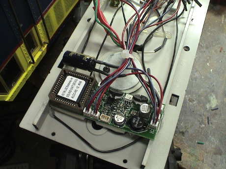
 The
Digitrax DG583S decoder is mounted to the frame in the center with
foam tape. It is thin enough to fit under the batteries.
The
Digitrax DG583S decoder is mounted to the frame in the center with
foam tape. It is thin enough to fit under the batteries.
 The
ART-5495 accessory board was mounted across the rear of the frame
behind the rear most battery. The function wires had to run the
length of the frame from this board to the Dallee board in
front.
The
ART-5495 accessory board was mounted across the rear of the frame
behind the rear most battery. The function wires had to run the
length of the frame from this board to the Dallee board in
front.
 While the 5490 receivers were working fine in a
Warbonnet FA/FB pair, I elected to convert them to DCC. I wanted to
use the receivers in battery power installations and the Zimo
MX65S/N DCC decoders cost less than a new 5490. I had one decoder
laying around already so I only needed to buy one more instead of
two 5490's.
While the 5490 receivers were working fine in a
Warbonnet FA/FB pair, I elected to convert them to DCC. I wanted to
use the receivers in battery power installations and the Zimo
MX65S/N DCC decoders cost less than a new 5490. I had one decoder
laying around already so I only needed to buy one more instead of
two 5490's.
The installation is pretty straightforward considering that the locos had 5490's in them already. The 5490's were removed and the Zimo decoders were wired in their place. On the FB, which has no sound, the installation was very simple, just 4 wires were moved from the 5490 to the Zimo. On the FA, the whistle and bell control required the addition of two optical isolators (at least they require it because I prefer to do it that way). The schematic below describes the installation.
Sierra claims that the Sierra is compatible with DCC in their Technical Note #7. However, this isn't always true. Some decoders don't interface to it well. The Zimo is one of those. The method that Zimo uses do implement their H-bridge motor controller makes it work much the same as a 5490. The Zimo turns on one of the high side motor control transistors whenever it running at any speed other than zero. It then switches the low side transistor on the other side of the H-bridge. This means that it requires much the same interface circuitry as the 5490.
 The
problem with the Sierra recommended circuit is that the Sierra's
speed response with respect to input voltage is highly nonlinear.
It takes 2.5 volts on pin 7 or 8 to get the Sierra to budge off
idle. Then even at the high sensitivity setting, about 5.5 volts is
required to reach notch 8. This means that the engine will be
running at about half speed before the Sierra even gets to notch 1.
Also, to make the automatic bells and whistles work, the input
voltage to the Sierra MUST go to zero when the locomotive stops.
Dealing with this nonlinearity has caused me about a year of grief,
but I've finally fixed it.
The
problem with the Sierra recommended circuit is that the Sierra's
speed response with respect to input voltage is highly nonlinear.
It takes 2.5 volts on pin 7 or 8 to get the Sierra to budge off
idle. Then even at the high sensitivity setting, about 5.5 volts is
required to reach notch 8. This means that the engine will be
running at about half speed before the Sierra even gets to notch 1.
Also, to make the automatic bells and whistles work, the input
voltage to the Sierra MUST go to zero when the locomotive stops.
Dealing with this nonlinearity has caused me about a year of grief,
but I've finally fixed it.
The trick involves a modification of Sierra interface circuit shown in the Technical Note #6. A pair of optoisolators is still used, wired with the LEDs back to back. Depending on the motor direction, one or the other of them will respond and turn on its associated phototransistor. At the first hint of a motor drive signal, the positive going voltage at the emitter of the 4N33 optoisolator turns on the 2N2222 (or any other general purpose NPN transistor) which in turn turns on the 2N2907 (or any other general purpose PNP transistor). The 2N2907 then pulls up the Sierra's pin 7 or 8 to about 2.5 volts which is just below the voltage that will cause it to transition from idle to notch 1. As the motor pulse width increases, the 4N33 pulls up pin 7 or 8 even harder until at full motor speed, the output voltage reaches about 5.5 volts, enough to reach notch 8. When the motor pulses cease, the 4N33 turns off which in turn turns off the 2N2222 and 2N2907 allowing the voltage at pin 7 or 8 to drop to zero so that the Sierra can detect that the motors have stopped. It can then blow the single stop whistle signal and reset itself so that it can detect if the motor direction is changed when the motor starts again. Then the Sierra can either blow two or three toots and turn on the correct headlight. The series diode prevents the circuit from latching itself on.
Another trick that can be done is to preset the engine speed off idle as soon as the motor controller starts to make output pulses. This is done by reducing the 3.3K resistor to about 1K. This will set the engine speed at the top of notch 1 at the very beginning. To bring the loco off idle, advance the throttle to its first speed step and then wait a couple of seconds for the loco sound to rev up. Then start increasing the throttle and the sound system will start ramping through its notches just as the engine begins to move. Notch 8 will be achieved at maybe 60% of full throttle and stay there through the higher speed ranges.
The supply voltage to this circuitry was increased to 9.8 volts (from 9 in the 5490 installation) to allow the circuit to pull a little harder on pins 7 and 8. The increased voltage resulted in increased charging current for the battery, so the 10 ohm current limiting resistor was increased to 22 ohms to keep the charging current down below 30 mA at the trickle level. The LM317 was also getting pretty hot so a 43 ohm resistor was added between it and the rectifier to take some of the thermal load off the LM317.
DCC has finer speed control than the 5490 as the speed steps are smaller and the back EMF control of the Zimo decoders allows the locos to steadily creep along. This showed as soon as I first fired the loco up.
In the original installation, I used optical isolators for the bell and horn triggers. It turns out that I was being overly cautious and, at least for the combination of a Zimo decoder, the Sierra and the interface circuit, the additional isolation provided by the bell and horn triggers is not necessary. Another function was wired to fire off the dynamic brake and two more were used to provide a remote volume/programming function even though this unit has a volume/programming physical switch. I can see the Sierra through a porthole on the side of the loco so that it can be programmed from the outside with either the switch located underneath or via DCC functions F7 (Vol+) and F8 (Vol-). I used DecoderPro to remap the Zimo function wires to these otherwise unused functions. F7 and F8 match the functions used for volume control on the Phoenix P5 so that they are easier to remember.
 I have another FA/FB set in
ATSF blue/yellow paint. I bought these locos used for $20 each.
From the looks of the wheels, they were high milers too. They also
ran poorly. These were the ones that I developed my brick fix process on. After that, the
locos ran pretty good, but they got little use as I had converted
the layout to DCC and these got left behind as I hadn't settled on
a good decoder at the time. I pulled them off the shelf and tested
them, they ran well after a wheel cleaning. I had just received
some MRC AD322
8 amp decoders, they were being blown out at $11 each. I got them
as sacrificial or placeholder decoders because DG583S units I had
on back order just were not getting shipped. I was tired of
waiting. I wanted to try one in a C-16 where the DG580L that was in
there was so flakey. I also wanted to put one in a Center Cab.
However, neither of these plans panned out as the decoders were
just too big to fit. However, they would fit in the old FA's and
the MRC AD322 also has diesel sound, after a fashion, on board.
I have another FA/FB set in
ATSF blue/yellow paint. I bought these locos used for $20 each.
From the looks of the wheels, they were high milers too. They also
ran poorly. These were the ones that I developed my brick fix process on. After that, the
locos ran pretty good, but they got little use as I had converted
the layout to DCC and these got left behind as I hadn't settled on
a good decoder at the time. I pulled them off the shelf and tested
them, they ran well after a wheel cleaning. I had just received
some MRC AD322
8 amp decoders, they were being blown out at $11 each. I got them
as sacrificial or placeholder decoders because DG583S units I had
on back order just were not getting shipped. I was tired of
waiting. I wanted to try one in a C-16 where the DG580L that was in
there was so flakey. I also wanted to put one in a Center Cab.
However, neither of these plans panned out as the decoders were
just too big to fit. However, they would fit in the old FA's and
the MRC AD322 also has diesel sound, after a fashion, on board.
The AD322 is a fairly big board as decoders go. It has only one switch FET and uses a relay for reversing, similarly to the Aristo ART-5490 receiver. The power, motor and headlight leads are on the left, the extra function and speaker leads are on the right.
 I could have mounted the
decoder on the rear weight, but it interfered with the smoke
generator hose. Instead, I pulled the "engine" out and removed the
interior lighting and mounted the decoder right on top of the
little PWB with foam mounting tape.
I could have mounted the
decoder on the rear weight, but it interfered with the smoke
generator hose. Instead, I pulled the "engine" out and removed the
interior lighting and mounted the decoder right on top of the
little PWB with foam mounting tape.
I could have cut traces on the PWB to isolate the motors but I chose instead to just cut the motor wires leading to the trucks. The red and green wires go to the motor. I tapped power for the decoder from the stubs of the motor wires that go to the PWB. The wires that lead to the trucks were connected to the motor output of the AD322. Note that the trucks are reversed with respect to each other so that the red wire of one truck mates with the green wire from the other truck.
I also wired the headlight to the decoder. It is a simple matter to disconnect the headlight from the binding posts just in front of the cab and wire them back to the blue and white wires of the decoder. I also connected the yellow wire back to the headlight through a 200 ohm resistor so that it would dim in reverse.
The decoder has special lighting attributes that are assigned to the other function wires, but they are enabled as a set and I really didn't want to bother with them so I just taped off the brown, green and purple function wires.
The sound part of the decoder is marginal at best. The bell and horn are passable, but the engine sound is pretty poor. There seems to be just two notches, idle and run 8. Further, there is no volume control and the thing is fairly loud. Fortunately, F8 will turn it off.
The AD322 has a motor PWM drive frequency of about 250 Hz, much higher than the older versions at 30 Hz but much lower than the more modern systems that pulse at 20 kHz or higher where they cannot be heard at all. Since the motor drive is in the form of pulses, there are harmonics at 250 Hz intervals that fill out the spectrum right through the most sensitive part of the audible frequency range. The loco will make a pronounced buzzing sound at the lowest speed steps that will decrease in intensity as the loco speeds up. This is actually less annoying than the growling that the lower frequency decoders make, but it is still objectionable. With the sound system turned on though, its hard to hear this hash over the noise that the sound system makes.
I also did a nearly identical install in the matching FB unit except that there is no lighting left in that unit and I didn't install a speaker for the sound. The awful hash that the FA makes is enough. The locos operate well with each other in a consist and match speed well without having to go to the trouble of adjusting Vmid and Vmax. I did set Vstart on both of them to CV2=5 to get them both to barely start moving at speed step 1. There is no programmable speed table in the AD322 so if you have to match speed, you have to do it with the 3 point method.
It did occur to me that part of the buzzing might be coming from leakage of the motor pulses into the sound system but this does not appear to be the case. The FB, without even a speaker, makes the same PWM noise as the FA. There MAY be some contribution due to the sound system, but if there is, it is slight.
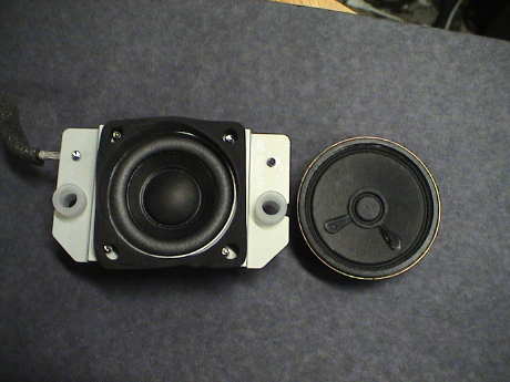 The AD322 comes with a
2" speaker of dubious quality, it's the round one in this photo. I
hooked up a medium quality HiFi speaker to the decoder and there is
enough bass in there to make a better speaker worth it.
The AD322 comes with a
2" speaker of dubious quality, it's the round one in this photo. I
hooked up a medium quality HiFi speaker to the decoder and there is
enough bass in there to make a better speaker worth it.
Last week, I bought a dozen high quality 2" speakers at a swap meet. These were installed in a long plastic baffle that looks like it would mount in the roofline of a car. The metal bracket also has a foam seal on it to allow the speaker cone to extend forward without hitting something.
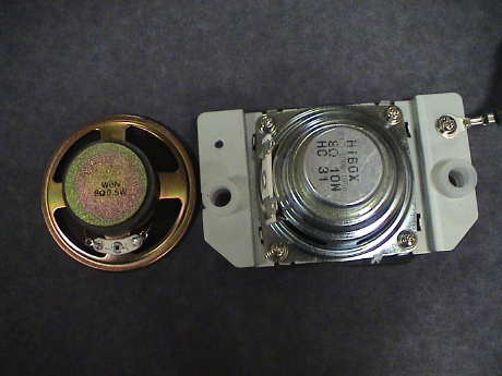 The back view shows the
bracket a little better. It turns out that this bracket fits
perfectly into the fuel tank of the FA. Two beads of hot glue hold
it in place with the foam seal compressed against the bottom of the
tank, which is now full of holes. This actually makes a fair
speaker enclosure.
The back view shows the
bracket a little better. It turns out that this bracket fits
perfectly into the fuel tank of the FA. Two beads of hot glue hold
it in place with the foam seal compressed against the bottom of the
tank, which is now full of holes. This actually makes a fair
speaker enclosure.
 The next day, I put the FA
and FB on the track to shoot some video and the FB couldn't decide
what to do. It was trying to buck the FA even though it was
consisted properly. Then the booster current spiked and the booster
shut down. When the booster came back on, the decoder in the FB
simply exploded with a loud pop and a considerable stink. The three
terminal regulator on the decoder blew up for reasons unknown. I
pulled it and checked for motor isolation, that was ok. I put
another one in, programmed it's address and start voltage and off
it went. I would guess that this is a case of infant mortality in a
grand fashion. It could have also been that the AD322 was trying to
analog convert and running the other way. In any event, I disabled
analog conversion on ALL the AD322's and haven't lost another
one.
The next day, I put the FA
and FB on the track to shoot some video and the FB couldn't decide
what to do. It was trying to buck the FA even though it was
consisted properly. Then the booster current spiked and the booster
shut down. When the booster came back on, the decoder in the FB
simply exploded with a loud pop and a considerable stink. The three
terminal regulator on the decoder blew up for reasons unknown. I
pulled it and checked for motor isolation, that was ok. I put
another one in, programmed it's address and start voltage and off
it went. I would guess that this is a case of infant mortality in a
grand fashion. It could have also been that the AD322 was trying to
analog convert and running the other way. In any event, I disabled
analog conversion on ALL the AD322's and haven't lost another
one.
And this is the video with examples of all the good and bad sounds that the AD322 makes.
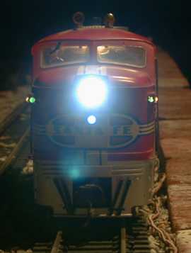 Since the Sierra has
programmable lighting outputs, I elected to connect the headlight
to the Sierra to take advantage of the reversing headlight function
that was lost when the 5490 was installed. The stock Aristo
headlight runs at 18 volts and won't light at all from the 6 volts
the Sierra provides so I changed out the headlight to a bright White LED to get more
brightness and allow the light to run from 6 volts.
Since the Sierra has
programmable lighting outputs, I elected to connect the headlight
to the Sierra to take advantage of the reversing headlight function
that was lost when the 5490 was installed. The stock Aristo
headlight runs at 18 volts and won't light at all from the 6 volts
the Sierra provides so I changed out the headlight to a bright White LED to get more
brightness and allow the light to run from 6 volts.
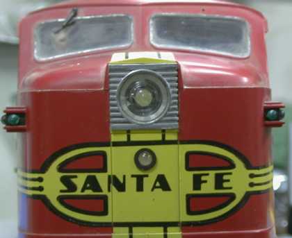 The Sierra has two lighting outputs and I like
Mars lights so I wanted to install a second LED below the stock
headlight as a Mars light. I looked in my book collection and on
the internet for a photo of an FA with a second headlight and found
none. However, I did find a painting of a Warbonnet PA-1 with a
second headlight right in the position shown in the photo. Since
there never actually was an FA-1 painted in Warbonnet, that was
close enough for me, out came the drill and in went the second
headlight.
The Sierra has two lighting outputs and I like
Mars lights so I wanted to install a second LED below the stock
headlight as a Mars light. I looked in my book collection and on
the internet for a photo of an FA with a second headlight and found
none. However, I did find a painting of a Warbonnet PA-1 with a
second headlight right in the position shown in the photo. Since
there never actually was an FA-1 painted in Warbonnet, that was
close enough for me, out came the drill and in went the second
headlight.
 Even
if a Sierra isn't being used to drive the headlight, a white LED
can be installed in place of the existing lamp. For regular track
power, just wire a 1K ohm resistor in series with the LED. The
longer lead of the LED will wire to the existing diode. For the
lower voltage output of the Sierra, use a 270 ohm resistor. The
headlight can be accessed by removing the number board lamp
assembly (one small screw) and then pull the two screws out of the
clear plastic light guides and slip them outward a half inch or so.
Then pull the original headlamp from the holder and stick a 5 mm
white LED back in all the way. In this photo, the original lamp has
already been removed and the LED installed. The black plastic
sleeving is a good light shield and has been reinstalled.
Even
if a Sierra isn't being used to drive the headlight, a white LED
can be installed in place of the existing lamp. For regular track
power, just wire a 1K ohm resistor in series with the LED. The
longer lead of the LED will wire to the existing diode. For the
lower voltage output of the Sierra, use a 270 ohm resistor. The
headlight can be accessed by removing the number board lamp
assembly (one small screw) and then pull the two screws out of the
clear plastic light guides and slip them outward a half inch or so.
Then pull the original headlamp from the holder and stick a 5 mm
white LED back in all the way. In this photo, the original lamp has
already been removed and the LED installed. The black plastic
sleeving is a good light shield and has been reinstalled.
 The LED can be held in
place by soldering the current limiting resistor to one lead
(either one) and attaching it to the shell with a dab of hot glue.
The other LED if used can be held in place the same way. Mine came
with a black plastic grommet assembly that fit nicely in a 1/4"
hole.
The LED can be held in
place by soldering the current limiting resistor to one lead
(either one) and attaching it to the shell with a dab of hot glue.
The other LED if used can be held in place the same way. Mine came
with a black plastic grommet assembly that fit nicely in a 1/4"
hole.
 The Aristo FA sits way
too high on its trucks. This has been long recognized and a few
pioneers have, with razor saw in hand, hacked at the FA to bring it
to a more credible height.
The Aristo FA sits way
too high on its trucks. This has been long recognized and a few
pioneers have, with razor saw in hand, hacked at the FA to bring it
to a more credible height.
 The method described
below removes 0.2" from the overall height of the loco by
remounting the trucks closer to the body. I am following the method
described by Larry Cooper in an article posted at Large Scale
Central Articles Index. Larry is in turn followed the general
technique described by Orlando Pinelli in the August/September 1993
issue of Outdoor Railroader Magazine (page 64).
The method described
below removes 0.2" from the overall height of the loco by
remounting the trucks closer to the body. I am following the method
described by Larry Cooper in an article posted at Large Scale
Central Articles Index. Larry is in turn followed the general
technique described by Orlando Pinelli in the August/September 1993
issue of Outdoor Railroader Magazine (page 64).
The method is technically easy, but it is a little labor intensive. Basically, the bolsters that the truck A frames are currently attached to are sliced off the bottom of the frame and remounted on the top of the frame. The hardest part of the job is taking the locomotive completely apart. You will be manhandling the frame and don't want any parts hanging off it while you are working.
Follow the instructions in the next section to gain access to the inside of the loco. Set the shell aside. Note the color and location of the wires leading from the frame to the truck sideframes and draw a map as to where they go. You will need this information later to properly reconnect them. Then strip everything off the frame. The whole disassembly job takes maybe 15 minutes because there is nothing that is really difficult to remove.
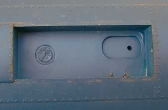
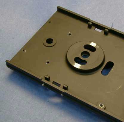 This is
the bottom side of the stock frame. A hacksaw blade will be used to
cut the two round bolsters off flush to the bottom of the
frame.
This is
the bottom side of the stock frame. A hacksaw blade will be used to
cut the two round bolsters off flush to the bottom of the
frame.
Note the wear marks on the raised portion of the truck support. There are two ridges on the truck frame that caused these. When the FA is lowered, the worn surface will be flush with the rest of the frame and the area of truck support will widen. This will impede the truck from rocking back and forth and MAY result in increased derailments on track that has lateral level issues. There is a fix for this, described below.
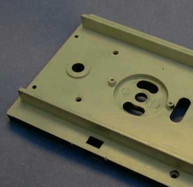 This is
the topside of the unmodified frame. When the bolsters are sliced
off, two large round holes will be left. Note the two small posts
next to each bolster. These don't serve any useful function anymore
and will be in the way. They need to be cut flush to the frame
surface too.
This is
the topside of the unmodified frame. When the bolsters are sliced
off, two large round holes will be left. Note the two small posts
next to each bolster. These don't serve any useful function anymore
and will be in the way. They need to be cut flush to the frame
surface too.
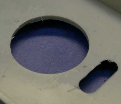 A finetooth hacksaw
blade can be worked into position to cut off the bolsters. Some
damaged paint is inevitable. Try to get the frame surface as flat
as possible as this will be the new bearing surface for the power
brick A frames. When the bolster is gone, there will be a 1-1/4"
hole left in the frame.
A finetooth hacksaw
blade can be worked into position to cut off the bolsters. Some
damaged paint is inevitable. Try to get the frame surface as flat
as possible as this will be the new bearing surface for the power
brick A frames. When the bolster is gone, there will be a 1-1/4"
hole left in the frame.
 This is a diagram
that shows the before and after configurations of the bolster. Once
the bolster is cut off the frame , it needs a ledge cut in it so
that it will fit back through the original hole.
This is a diagram
that shows the before and after configurations of the bolster. Once
the bolster is cut off the frame , it needs a ledge cut in it so
that it will fit back through the original hole.
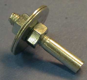 A simple wheel arbor can be made from a 2" x
5/16" bolt with the head cut off. A couple of 5/16" nuts and 1-1/4"
fender washers complete the arbor. The 1-1/4" washer is important.
This is the exact diameter of the hole in the frame so that the
bolster can be clamped between the washers and turned in a lathe,
drill press or even a power drill down to the diameter of the
washer and it will just fit. The cut needs to the same depth as the
thickness of the frame, 0.100" so that the bolster will eventually
be flush with the bottom of the frame.
A simple wheel arbor can be made from a 2" x
5/16" bolt with the head cut off. A couple of 5/16" nuts and 1-1/4"
fender washers complete the arbor. The 1-1/4" washer is important.
This is the exact diameter of the hole in the frame so that the
bolster can be clamped between the washers and turned in a lathe,
drill press or even a power drill down to the diameter of the
washer and it will just fit. The cut needs to the same depth as the
thickness of the frame, 0.100" so that the bolster will eventually
be flush with the bottom of the frame.
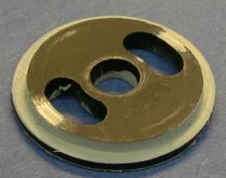 This is a bolster
after being cut down to fit. The lip sets the proper height and
allows a large surface area for gluing the bolster back into the
frame.
This is a bolster
after being cut down to fit. The lip sets the proper height and
allows a large surface area for gluing the bolster back into the
frame.
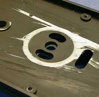 When the bolster is reattached, it will be flush with the bottom of
the frame. I used Zap CA to reattach the bolsters, epoxy would work
as well. The truck A frame itself will ride on the frame bottom
surface so that little force will be applied to the bolster itself.
Set up this way, the glue joint could break and the truck still
wouldn't fall off.
When the bolster is reattached, it will be flush with the bottom of
the frame. I used Zap CA to reattach the bolsters, epoxy would work
as well. The truck A frame itself will ride on the frame bottom
surface so that little force will be applied to the bolster itself.
Set up this way, the glue joint could break and the truck still
wouldn't fall off.
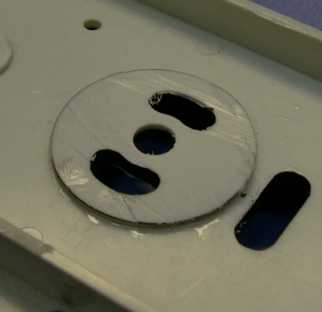 The lip
on the modified bolster is now on the top side of the frame. There
used to be a steel weight there. I elected to abandon the weight
because I had plenty of batteries in this loco for weight. If you
want to retain the weight there are three ways to handle it. The
weights can be spaced upwards on 1/4" styrene or wood spacers and
reattached with longer screws. The hole in the lower weight can be
drilled or filed out to 1.5". The weights could be replaced with
glued in lead fishing weights.
The lip
on the modified bolster is now on the top side of the frame. There
used to be a steel weight there. I elected to abandon the weight
because I had plenty of batteries in this loco for weight. If you
want to retain the weight there are three ways to handle it. The
weights can be spaced upwards on 1/4" styrene or wood spacers and
reattached with longer screws. The hole in the lower weight can be
drilled or filed out to 1.5". The weights could be replaced with
glued in lead fishing weights.
At this point reassemble the locomotive except for the coupler mounts. Note that when the trucks are reattached, the rocking gearbox on both trucks should be on the end nearest the center of the loco.
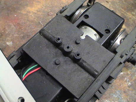 The
top of each truck has a ridge that runs laterally across the loco.
The part of the ridge right next to the posts used to ride on the
circular boss on the bottom of the original frame. This provided a
fairly narrow area of support, wide enough to support the body
upright, but narrow enough such that a truck can rock a little to
track well over track that has changes in the lateral level.
The
top of each truck has a ridge that runs laterally across the loco.
The part of the ridge right next to the posts used to ride on the
circular boss on the bottom of the original frame. This provided a
fairly narrow area of support, wide enough to support the body
upright, but narrow enough such that a truck can rock a little to
track well over track that has changes in the lateral level.
However, once the loco is lowered, the WHOLE ridge rides on the bottom of the frame and the trucks are impeded from rocking back and forth. This can cause wheels to lift on track that has changes in lateral level.
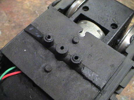 The fix
is to grind off part of the ridge on ONE truck to allow that one
some freedom of movement. The other one will support the body and
prevent it from rocking. The modified one can rock in relation to
the carbody to individually follow bad track. Leave about 1/4" of
the ridge intact. This is the area that is going to support the
weight of the loco.
The fix
is to grind off part of the ridge on ONE truck to allow that one
some freedom of movement. The other one will support the body and
prevent it from rocking. The modified one can rock in relation to
the carbody to individually follow bad track. Leave about 1/4" of
the ridge intact. This is the area that is going to support the
weight of the loco.
 Since the
couplers on the loco are body mounted, the mounts will have to be
modified as well to lift the couplers back to the correct height.
The rear coupler mount can be adjusted by cutting out a 0.2"
section of the mount and gluing it back together. The epoxy fillet
is critically important to beef up the joint because most of the
force applied will be at that part of the joint.
Since the
couplers on the loco are body mounted, the mounts will have to be
modified as well to lift the couplers back to the correct height.
The rear coupler mount can be adjusted by cutting out a 0.2"
section of the mount and gluing it back together. The epoxy fillet
is critically important to beef up the joint because most of the
force applied will be at that part of the joint.
The front coupler mods will depend on the kind of coupler that you are using. On an FB, the change will be identical to the rear coupler of the FA. I had a Kadee mounted in this FA so I just shaved the ridges on the side of the post down 0.2" and then cut 0.2" from the top of the post.
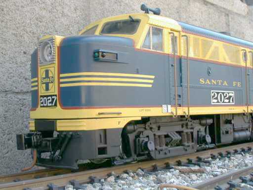 The fuel
tank and pilot both hang 0.2" lower, but since they were really
high before, they still clear the track by a respectable amount and
actually look better.
The fuel
tank and pilot both hang 0.2" lower, but since they were really
high before, they still clear the track by a respectable amount and
actually look better.
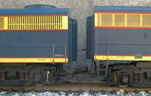 The small reduction
in height isn't particularly significant in the overall height of
the loco, but since its taken all from the truck to frame spacing,
that particular part looks much better.
The small reduction
in height isn't particularly significant in the overall height of
the loco, but since its taken all from the truck to frame spacing,
that particular part looks much better.
Jerry McColgan wrote me with some photos of a tool he made to make removal of the back end of the FA shell easier.
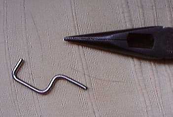 "I thought you might be interested to
know that I have designed a quick disassembly tool that really
simplifies removing the shell of an FA-1 or FB-1 with less chance
of breaking the tabs on the end panels. It is simply a length of
coat hanger cut and bent to fit in the slot in the chassis next to
the ladders."
"I thought you might be interested to
know that I have designed a quick disassembly tool that really
simplifies removing the shell of an FA-1 or FB-1 with less chance
of breaking the tabs on the end panels. It is simply a length of
coat hanger cut and bent to fit in the slot in the chassis next to
the ladders."
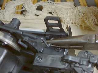 "By inserting it I
can pull the chassis end up from the inside by leveraging the
needle nose pliers against the end of the car. The result is
quicker removal with less chance of damage. I had 36 FA/B-1's to
modify and needed something to help so I came up with this."
"By inserting it I
can pull the chassis end up from the inside by leveraging the
needle nose pliers against the end of the car. The result is
quicker removal with less chance of damage. I had 36 FA/B-1's to
modify and needed something to help so I came up with this."
"I'm sure you already know that the screws holding the flaps at the ends of the cars and the hand rails also frequently need to be backed out as they tend to hold the chassis down."
No, I didn't know that Jerry, I usually just force the shell off.
© 1997-2010 George Schreyer
Created Oct 18, 1997
Last Updated November 21, 2010