LGB 2060 Tips
[ Home ] [ Up ] [ Previous Page ] [ Next Page ]
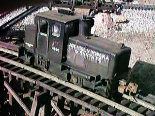 This LGB 2060
industrial switcher originally came in a starter set. It doesn't look
too much like the original due to the black paint and weathering. It
was originally rather bright orange color. LGB fanatics may cringe at
the changes, but LGB locos make good razor saw fodder because they
typically run well so that the eventual bash runs well too even though
it may look trashed.
This LGB 2060
industrial switcher originally came in a starter set. It doesn't look
too much like the original due to the black paint and weathering. It
was originally rather bright orange color. LGB fanatics may cringe at
the changes, but LGB locos make good razor saw fodder because they
typically run well so that the eventual bash runs well too even though
it may look trashed.
The purpose of this page is to document the installation of DCC into the loco and then the eventual removal of this equipment from the
loco due to decoder related performance issues. Then batteries and a radio control receiver were installed. Sound
also went in. Then, many years later and with a much better decoder, DCC went back in in addition to all the other stuff. This time around, it ran fine on DCC.
Contents
Isolating A Three Terminal LGB Motor Block
Many LGB locos are wired to allow them to accept a DCC decoder. The
motor leads are brought out of the power brick separately from the
track pickups. These locos are usually designated with a "D" at the end
of the model number or on the bottom of the brick or by some sticker
that indicates DCC or MTS compatibility. However, this little 2060 that
came in an industrial starter set is the older version with only three
terminals on the top of the brick. It is not difficult to modify the
brick to isolate the motor.
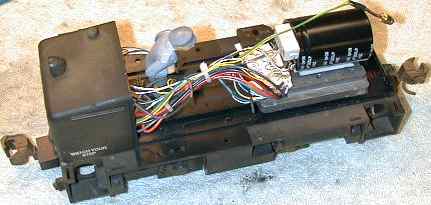
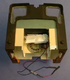
To gain access to the wiring, most of the loco must be disassembled.
First remove two screws at the end of each hood. Then remove the two
steps under the cab and two more screws hidden way up in the tanks.
These screws are accessed through holes in the bottoms of the tanks.
With the cab loosened, the hoods will come off easily, then you can
actually remove the cab.
There are two strap like brackets on the underside of the loco that
hold the brick to the bottom of the frame. Remove the four screws that
hold these brackets in place and pull out the brick. Then remove the
wire terminals from the brick by pulling on each one. Note the colors
of the wires that go to each post. Then remove two screws that hold on
the brick cover and remove the cover. The motor can then be just pulled
out of the brick.
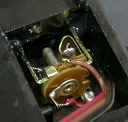
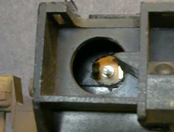
There are three metal posts sticking out of the top of the brick.
They are labeled br (brown), gr (green) and ws (weiss or white, but
actually the wires were black). The black leads are the common leads
and this is the area that needs modification to accept DCC. This engine
doesn't have a motor switch, so the brown and green terminals are
jumpered.
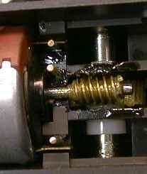 The motor terminal tabs rest against the two
outer posts. Electrical contact is assured by the spring action of the
motor tab edges against the posts. The single inner post goes to the
power pickups on one side. The outer post by itself goes to the power
pickups on the other side. The other outer post doesn't go anywhere.
Power is delivered to the post from the top through a green jumper
wire. DCC installations absolutely require that BOTH
motor leads be isolated from all other wiring and connected only to the
DCC decoder itself. A simple and reversible modification is needed to
isolate the motor.
The motor terminal tabs rest against the two
outer posts. Electrical contact is assured by the spring action of the
motor tab edges against the posts. The single inner post goes to the
power pickups on one side. The outer post by itself goes to the power
pickups on the other side. The other outer post doesn't go anywhere.
Power is delivered to the post from the top through a green jumper
wire. DCC installations absolutely require that BOTH
motor leads be isolated from all other wiring and connected only to the
DCC decoder itself. A simple and reversible modification is needed to
isolate the motor.
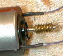 The motor tabs leave the motor at an angle
with respect to the posts so that an edge presses against the post. All
that is necessary is to use a pair of needle nose pliers to gently bend
the motor tabs so that they are parallel to the posts and do not touch
them. Wires are then soldered to the ends of the tabs and insulated
with heat shrink tubing.
The motor tabs leave the motor at an angle
with respect to the posts so that an edge presses against the post. All
that is necessary is to use a pair of needle nose pliers to gently bend
the motor tabs so that they are parallel to the posts and do not touch
them. Wires are then soldered to the ends of the tabs and insulated
with heat shrink tubing.
With the engine disassembled to this level, this is a good time to
lubricate the engine with gear grease on both axle gears and oil on the
axle bushings.
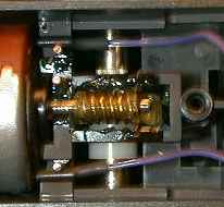 These wires
are then routed by the posts and up through an access hole in the brick
cover and along with the rest of the wiring up into the shell. I didn't
bother to color code my motor wires because I usually figure out the
correct polarity by test anyway. The LGB wiring is unmodified at this
point and the original wires can be pressed back on the proper posts
after the cover is reinstalled.
These wires
are then routed by the posts and up through an access hole in the brick
cover and along with the rest of the wiring up into the shell. I didn't
bother to color code my motor wires because I usually figure out the
correct polarity by test anyway. The LGB wiring is unmodified at this
point and the original wires can be pressed back on the proper posts
after the cover is reinstalled.
[ Top ]
DCC Decoder Installation
The 2060 and most other starter set engines are so simple the that
DCC wiring is a snap once the motor is isolated. If directional
lighting is not desired, then all that is necessary is to tap into one
set of lighting wires for the DCC power input and to wire the two new
wires to the DCC decoder motor output.
I chose to wire the headlights to the decoder to allow directional
lighting. This is done by cutting the headlight wires about 1.5" away
from the bulb sockets and splicing extension wires on them and wiring
them to the decoder per the decoder manufacturer's instructions. I
chose to extend the lighting wires because the rear headlight wires
were too short to make it easy to get the rear hood back on. The
remaining long wires that went to the front headlight were insulated
and left ready to hook to a future sound system. The wire stubs that
went to the rear headlight were used to power the DCC decoder.
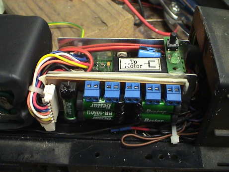
 The decoder (a Digitrax DG580L) was installed
under the front hood. The decoder is mounted crossways on the rear of
the weight with some foam tape. A large storage capacitor (47,000 uF,
25 V) is also mounted on the weight. Refer to my DCC Tips page for more information on the
capacitor. I didn't cut any of the decoder wires so the extra length is
simply looped around to get it out of the way.
The decoder (a Digitrax DG580L) was installed
under the front hood. The decoder is mounted crossways on the rear of
the weight with some foam tape. A large storage capacitor (47,000 uF,
25 V) is also mounted on the weight. Refer to my DCC Tips page for more information on the
capacitor. I didn't cut any of the decoder wires so the extra length is
simply looped around to get it out of the way.
I typically don't pay much attention to the polarity of the motor or
decoder power wires until I am ready to wrap up the installation. I
just connect them and test the engine. If the engine goes the right way
when running on DCC, the motor wires are correct. If not, I just
reverse the motor wires and do a final clean up on the connections.
I then check the direction of the engine in analog mode by putting
an unconverted engine on the same track. If the engines go the same way
under regular track power, then the power leads are correct. If not,
the decoder power leads are reversed and the connections are cleaned
up.
Large scale locos use the opposite polarity convention as compared
to HO, so the manufacturer's instructions about the left and right
rails must be reversed. I've tried to keep the instructions straight,
but I usually get one of the connections wrong anyway so I've adopted
the cut and try approach. It works for me.
[ Top ]
Sound Installation With A Soundtraxx DSX Sound
Only Decoder
 This is a little engine, so I chose to
install a little sound system in it. I selected a Soundtraxx DSX sound
only decoder. This is a DCC decoder that doesn't have any motor
controls in it, it reads the DCC packets and creates and controls
sounds instead. I used and EMD 2-stroke type sound system, probably not
appropriate for this loco, but it sounds like a diesel anyway. The
audio output power is low by large scale sound system standards, but
since I was going to drive a small speaker, a lot of audio power would
not be usable anyway.
This is a little engine, so I chose to
install a little sound system in it. I selected a Soundtraxx DSX sound
only decoder. This is a DCC decoder that doesn't have any motor
controls in it, it reads the DCC packets and creates and controls
sounds instead. I used and EMD 2-stroke type sound system, probably not
appropriate for this loco, but it sounds like a diesel anyway. The
audio output power is low by large scale sound system standards, but
since I was going to drive a small speaker, a lot of audio power would
not be usable anyway.
The Digitrax motor decoder and the Soundtraxx sound decoder are
wired in parallel to the track. Each is programmed to the same address
so they both respond to commands directed to the engine. Wiring two
decoders in parallel pretty much wipes out the capability to program
either one on the programming track as the command station sees too
much load. In any event, the storage capacitor also makes programming
on the programming track impossible anyway. I set the decoder address
independently before they were wired together so that once they are
installed, OPS mode programming can be used to program both of them.
I'll only need to mess with the wiring to disconnect them if I choose
to change their addresses.
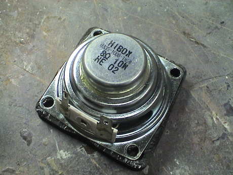
 The biggest problem in this installation is
finding room for a speaker. I fished around for quite awhile before I
concluded that a normal speaker just wasn't going to fit. This 1"
speaker that came with a Dallee system. The photo is about twice its
real size. I determined that it could marginally handle the power of
the DSX and sound marginally acceptable IF it was
mounted in a proper enclosure. I also determined that the "long" hood
of the model would make an adequate enclosure if a few holes were
plugged up and the speaker was mounted so that it projected into the
cab. The sound could then escape the engine from the cab windows. Since
only one window is normally open, I had to remove the rear window piece
to allow enough sound to escape.
The biggest problem in this installation is
finding room for a speaker. I fished around for quite awhile before I
concluded that a normal speaker just wasn't going to fit. This 1"
speaker that came with a Dallee system. The photo is about twice its
real size. I determined that it could marginally handle the power of
the DSX and sound marginally acceptable IF it was
mounted in a proper enclosure. I also determined that the "long" hood
of the model would make an adequate enclosure if a few holes were
plugged up and the speaker was mounted so that it projected into the
cab. The sound could then escape the engine from the cab windows. Since
only one window is normally open, I had to remove the rear window piece
to allow enough sound to escape.
 To properly seal the hood area, the wiring had to be
cleaned up so that it was channeled along one side of the frame through
a gap near the cab floor. The wire bundle nearly fills the gap and
plugs it as good as it is going to get.
To properly seal the hood area, the wiring had to be
cleaned up so that it was channeled along one side of the frame through
a gap near the cab floor. The wire bundle nearly fills the gap and
plugs it as good as it is going to get.
 Some small tabs of styrene were used to plug the
remaining gaps. A long gap between the wall that the speaker is mounted
on and the floor is plugged by a strip of foam tape mounted to the
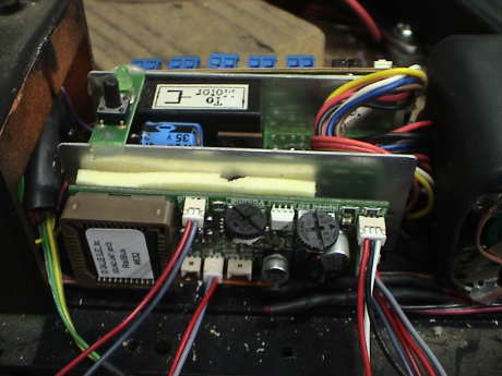
floor. The speaker itself is mounted with hot glue over a hole cut in
the wall of control stand in the cab. The DSX decoder is wedged in near
the speaker and held with a couple of globs of hot glue. The DSX
requires an external blocking capacitor in series with the speaker. It
is mounted under the DSX and hot glued in a corner. At large scale
track voltages, the DSX also needs a 39 ohm resistor in series with the
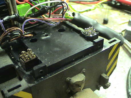
track power leads. It is inserted in one of the power wires. I used
DB-25 type connector pins to allow the cab assembly to be completely
separated from the frame in the same fashion that I use to interconnect power between engines
and cars.
Some small tabs of styrene were used to plug the
remaining gaps. A long gap between the wall that the speaker is mounted
on and the floor is plugged by a strip of foam tape mounted to the
floor. The speaker itself is mounted with hot glue over a hole cut in
the wall of control stand in the cab. The DSX decoder is wedged in near
the speaker and held with a couple of globs of hot glue. The DSX
requires an external blocking capacitor in series with the speaker. It
is mounted under the DSX and hot glued in a corner. At large scale
track voltages, the DSX also needs a 39 ohm resistor in series with the
track power leads. It is inserted in one of the power wires. I used
DB-25 type connector pins to allow the cab assembly to be completely
separated from the frame in the same fashion that I use to interconnect power between engines
and cars.
In operation, I found that the DSX has some problems. The low audio
output power coupled with a small speaker leaves something to be
desired in sound level. Second, and more serious, the DSX requires
excellent power continuity to operate properly. The 2060 doesn't have
particularly good power pickup and the DSX looses power and resets
often resulting in a series of pops and clicks when the track and wheels
are less than clean. Other large scale sound systems with batteries can
ride over power outages with little difficulty, the DSX cannot.
[ Top ]
DCC Removal
Even with all this work this engine's performance with DCC just
didn't meet my expectations. After a year or so, I removed the DCC
equipment and the engine became somewhat more tolerant to dirty track.
I would appear that DCC is more suited to larger locos with better
power pickup. In the future, I'll use DCC for the larger current hungry
stuff for its precise control, virtually unlimited power and auxiliary
function control. The smaller stuff will be left track powered or
converted to battery power. A set of high performance batteries will
drive a small loco well enough with the relatively light loads that
this kind of loco can handle. Further, it will still coexist with the
DCC stuff and it could run on track with any kind of power.
Update 11 Jun 10
Note that many years later, DCC was added back in with much better results, see below. The biggest change came from a better DCC decoder. The original DG580L was not a very good decoder and it responded poorly to track power interruptions. The much newer DG583S worked MUCH better.
Another important change was that in the interveaning years, I had developed a more effective and much easier track cleaning process using drywall screens dragged under a couple of track cleaning cars.
[ Top ]
Battery and Radio Control Installation in the
2060
Even running on straight track power and even with the sliders, the
2060 still doesn't have good enough power pickup to run on the same
dirty track that the larger engines will run on without difficulty.
There just aren't enough power pickup points to provide consistent
power when each pickup point has low reliability by itself. There were
two courses to follow, either clean the track or convert the loco to
battery power with radio control. The track power option is cheap, but
it doesn't allow command control. The radio control option involves
some capital investment, but will allow the loco to run consistently
and have command control. I choose to convert this loco to battery
power.
I had two choices to make, what kind of batteries and what kind of
R/C gear to install. The second choice was easy, I had recently
converted an FA that had an Aristo ART-5490 mini-receiver in it to DCC
so that the 5490 was available. I also had all the transmitters that I
would need so that the receiver was a zero cash option, an easy pick.
The 5490 isn't real small and the loco is so that there wouldn't be a
lot of room for batteries. After testing the top speed of the loco with
track power, I determined that I would need at least 16 volts to reach
the speed that I desired. The 5490 has about 2 volts of drop so that
implied about 18 volts worth of batteries. After playing with small
battery packs made of dead alkaline AA cells and duct tape, I
determined that I could get 15 AA sized cells in there with some room
to spare. The cells would be arranged in a "flat" pack of 5 cells
stacked 3 flats high. With the battery flats nested into each other, 15
AA cells just fit in the long hood with the front weight removed. The
weight would be supplied by the batteries. 15 cells of NiCad or NiMH
batteries gives a no load voltage of 18.75 volts.
The receiver would fit right behind the batteries, about 1/3 in the
hood and 2/3 in the cab. The engineer had to go and part of the
interior cab walls had to be hacked away, but it would just fit. The
short hood was left alone with the weight left in place. A sound system
might eventually fit in there.
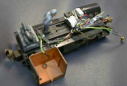
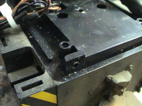
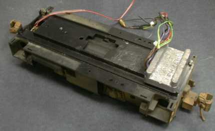 The 2060 was stripped
down to the frame to make room for the new stuff. Since the motor and
power contacts had already been wired up separately, the original
harness was left in place. The lead weights are held in by one screw
each accessible after the motor block is removed. Vertical clearance
for the RX was going to be tight, so the engineer was removed and his
mounting pad was ground off. The engineer is held in with a medium
strength adhesive. I found that by bending him to one side, one corner
of his mounting "puddle" lifted and I could pry it up to break the glue
joint.
The 2060 was stripped
down to the frame to make room for the new stuff. Since the motor and
power contacts had already been wired up separately, the original
harness was left in place. The lead weights are held in by one screw
each accessible after the motor block is removed. Vertical clearance
for the RX was going to be tight, so the engineer was removed and his
mounting pad was ground off. The engineer is held in with a medium
strength adhesive. I found that by bending him to one side, one corner
of his mounting "puddle" lifted and I could pry it up to break the glue
joint.
 In most battery installations some sort of power
switch is desirable to prevent the battery from being flattened while
the loco is not in service. This can be done with disconnecting type
power jack, but a switch is even handier. I used a sub-miniature toggle
switch with a 3/16" mount. This switch is tucked into the very front
corner of the long hood going down through the floor. The switch handle
is accessible through a hole behind the front step. Since the lower and
upper tier of batteries is offset half a cell width to the rear, there
is room for the switch body and also the headlight wire coming down
from the front of the hood.
In most battery installations some sort of power
switch is desirable to prevent the battery from being flattened while
the loco is not in service. This can be done with disconnecting type
power jack, but a switch is even handier. I used a sub-miniature toggle
switch with a 3/16" mount. This switch is tucked into the very front
corner of the long hood going down through the floor. The switch handle
is accessible through a hole behind the front step. Since the lower and
upper tier of batteries is offset half a cell width to the rear, there
is room for the switch body and also the headlight wire coming down
from the front of the hood.
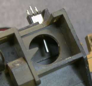
 A disconnecting type power jack is
installed in the front step well on the other side from the power switch. The jack mounting tabs were too large to
fit so they were trimmed and the jack was epoxied into place. I prefer
to mount switches and jacks in the floor of the locomotive so that
there is minimal wiring between the frame and the removable parts of
the loco.
A disconnecting type power jack is
installed in the front step well on the other side from the power switch. The jack mounting tabs were too large to
fit so they were trimmed and the jack was epoxied into place. I prefer
to mount switches and jacks in the floor of the locomotive so that
there is minimal wiring between the frame and the removable parts of
the loco.
 Since the
batteries will be bottled up inside the loco, external access is
desirable for connecting to the battery charger. The jack as mounted
can be accessed through the round hole behind the other front step.
Since the
batteries will be bottled up inside the loco, external access is
desirable for connecting to the battery charger. The jack as mounted
can be accessed through the round hole behind the other front step.
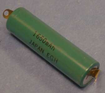 I choose to use a high capacity NiMH battery consisting of
15 of these tabbed cells. The tabs make construction of a battery pack
much easier. I have had poor luck with the reliability of NiCad
batteries in the past in many other applications. The manufacturers
claim that NiMH technology is more reliable and more tolerant to
partial charges and discharges than NiCad technology. The energy
density is higher, but so is the cost. This cell has a rated capacity
of 1650 mAh. By my tests, this kind of cell is good for at least 1500
mAh, at least when new.
I choose to use a high capacity NiMH battery consisting of
15 of these tabbed cells. The tabs make construction of a battery pack
much easier. I have had poor luck with the reliability of NiCad
batteries in the past in many other applications. The manufacturers
claim that NiMH technology is more reliable and more tolerant to
partial charges and discharges than NiCad technology. The energy
density is higher, but so is the cost. This cell has a rated capacity
of 1650 mAh. By my tests, this kind of cell is good for at least 1500
mAh, at least when new.
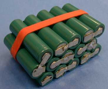 After the cells
were individually charged in a regular AA NiMH charger they were
soldered together into a pack. The rubber band was just to hold them
together while they were being handled and before they were made into a
complete pack. The pack was tested to make sure that it had the right
open circuit voltage to make sure that no cells had been wired
backwards. For freshly charged NiMH cells, you will expect about 1.4
volts per cell. The pack made 21.1 volts. Under load, it will drop
quickly to 1.25 volts per cell and stay there for most of their
discharge.
After the cells
were individually charged in a regular AA NiMH charger they were
soldered together into a pack. The rubber band was just to hold them
together while they were being handled and before they were made into a
complete pack. The pack was tested to make sure that it had the right
open circuit voltage to make sure that no cells had been wired
backwards. For freshly charged NiMH cells, you will expect about 1.4
volts per cell. The pack made 21.1 volts. Under load, it will drop
quickly to 1.25 volts per cell and stay there for most of their
discharge.
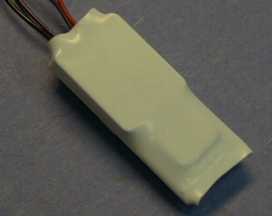
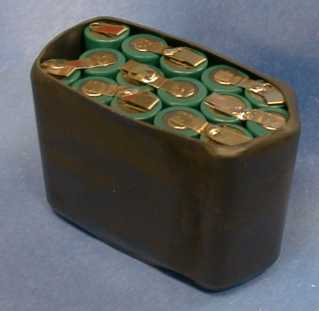 A piece of 3" shrink tubing was used to wrap
the pack permanently. This stuff shrugged off the puny hair dryer that
I use to shrink small tubing. I used a gas match on this stuff to get
it to shrink around the cells. After shrinking, this pack is solid.
A piece of 3" shrink tubing was used to wrap
the pack permanently. This stuff shrugged off the puny hair dryer that
I use to shrink small tubing. I used a gas match on this stuff to get
it to shrink around the cells. After shrinking, this pack is solid.
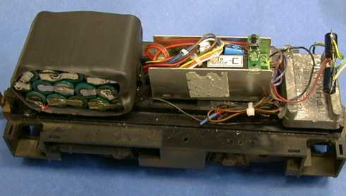
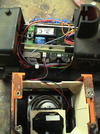
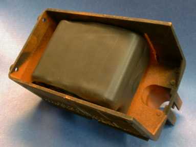 The pack was test fit into the hood.
Initially I attached it in the hood, but later I determined that it was
just as effective to attach it to the frame so that the wiring would
not be stressed and the engine could be more easily tested without the
hood.
The pack was test fit into the hood.
Initially I attached it in the hood, but later I determined that it was
just as effective to attach it to the frame so that the wiring would
not be stressed and the engine could be more easily tested without the
hood.
 This is the diagram of the
wiring. Its about as simple as it gets. I initially choose to run the
lights from the motor output but later I modified the circuit to allow
the lights to be directional. If they were wired to the battery, they
would burn absolutely constantly and be non directional They would also
drain the battery while the engine was on but standing. With the
addition of the diodes and capacitors, they are directional, nearly
constant intensity (as long as the engine is moving) and only one is on
at a time so that the battery drain is minimized. In the photo below,
the capacitors can be seen at the right of the photo before they were
insulated with shrink tubing.
This is the diagram of the
wiring. Its about as simple as it gets. I initially choose to run the
lights from the motor output but later I modified the circuit to allow
the lights to be directional. If they were wired to the battery, they
would burn absolutely constantly and be non directional They would also
drain the battery while the engine was on but standing. With the
addition of the diodes and capacitors, they are directional, nearly
constant intensity (as long as the engine is moving) and only one is on
at a time so that the battery drain is minimized. In the photo below,
the capacitors can be seen at the right of the photo before they were
insulated with shrink tubing.
The charge jack that I used is a disconnecting type. When the
charger is plugged in, the loco is disconnected automatically. This is
not really necessary because the power switch can be used to disconnect
the loco during charging. I have also provided current limiting for
battery charging from a 24 VDC source.
 The 5490 is attached to the floor with a
little Lexel adhesive. The code set switch is attached across the heat
sink of the 5490 with hot glue, but if it breaks off, I'll reattach it
with Lexel. It is just accessible through the center rear cab window
which the engineer has conveniently left open.
The 5490 is attached to the floor with a
little Lexel adhesive. The code set switch is attached across the heat
sink of the 5490 with hot glue, but if it breaks off, I'll reattach it
with Lexel. It is just accessible through the center rear cab window
which the engineer has conveniently left open.
The antenna wire was pinched as a result of some past problem and it
broke just about in half. The half that is left is not quite adequate
as the control range is only about 10'. Some more work was clearly
required on the antenna.
When the wire was repaired, and extended to it's original length, no
amount of fiddling with it would produce a control range exceeding
15'.
It finally stopped raining so I set up the loco for test. I loaded
it up just below wheel slip (just two Aristo box cars with metal
wheels) and let it run at full speed. It ran at nearly constant speed
for 3-1/2 hours and then abruptly slowed to a crawl. The receiver was
not perceptibly warm at the end of the test and the motor was just
warm. While this was a little less than I expected, it is good
enough.
As an experiment, I cut the antenna to about 6" and soldered the end
to a now unused power pickup. The result was rather amazing. The range
increased to at least 50' (the full width of my yard) and it appeared
that it would work well beyond that. The antenna circuit is DC blocked
so that if a track powered train is used at the same time, the DC
voltage will not damage the 5490. Even with a DCC signal (23 volts p-p)
on the track, the engine ran fine. It also ran fine with a regular loco
running on PWC on the same track with all its motor noise injected back
on the track. The 2060 also ran fine with another regular loco running
as the analog loco with DCC on the track. I can only conclude that the
experiment was a success.
[ Top ]
Sound Installation in the 2060
The LGB 2060 was the last loco at the GIRR that ran in stealth mode.
I elected to finish the job with an installation of a Dallee Railbus
sound system (#632) in the 2060. This sound system doesn't sound as
good as other railbus sounds, it has an acceptable engine beat that
increases tempo with motor speed but there are no gear shifts or diesel
engine transitions. The horn is a loud single chime air horn and the
bell is fair. However it only cost $94 shipping included, it makes good
sound volume and the Dallee boards integrate well into battery powered
environments.
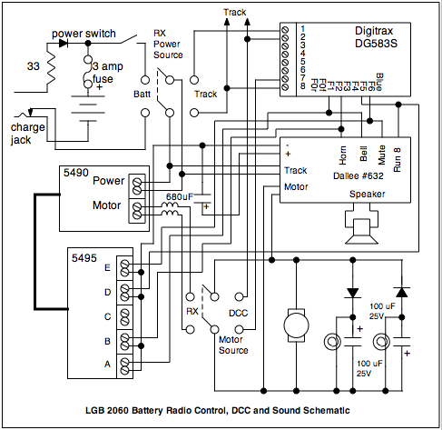
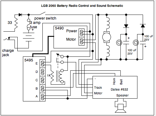 This is the schematic of the
installation. I did not disturb the previous wiring at all, this was a
complete add on. This 5490 receiver has the pigtail connector for a
5495 accessory board and I had one so I elected to use it to allow the
bell and horn to be triggered. I also used one output to act as a sound
power switch.
This is the schematic of the
installation. I did not disturb the previous wiring at all, this was a
complete add on. This 5490 receiver has the pigtail connector for a
5495 accessory board and I had one so I elected to use it to allow the
bell and horn to be triggered. I also used one output to act as a sound
power switch.
I had originally wired the power to the Dallee board through the "E"
reed relay on the ART-5495 board. This was done so that I could
remotely turn the sound system off and remove it's idle power
consumption as well. I could have elected to just mute the Dallee
board, but then it would draw idle current.
Aristo doesn't rate the current capability of the contacts of the
reed relays. I tried it and it seemed to work. However, after several
power cycles, the Dallee board stuck on. Tapping on the "E" relay would
cause it to release and the sound would go off, only to stick on again
later. The reed relay on the 5495 clearly wasn't up to the task.
I checked the relay with an ohmmeter and with almost no load, it
still seemed to work so I added another small 5 volt relay with better
contacts to actually switch the Dallee board. This one has a 10 mA
coil, so I added a 1K resistor in series with the coil to drop enough
voltage so that the coil wasn't overloaded. Then it worked
correctly.
 The 5495 accessory
board is just the same size as the side of the 5490 receiver. I
attached it to the side with some foam mounting tape. I had to hack out
some plastic from the cab liner on both sides to clear this board and
the Dallee board on the other side.
The 5495 accessory
board is just the same size as the side of the 5490 receiver. I
attached it to the side with some foam mounting tape. I had to hack out
some plastic from the cab liner on both sides to clear this board and
the Dallee board on the other side.
The 5495 accessory board has five reed relays that are activated by
the A through E buttons on the old 27 MHz TE transmitter. Buttons A and
B are intermittent, the reed switches are closed for only as long as
the button is held down. Buttons C, D and E latch but their state is
not remembered after a power cycle.
 On the other
side, I mounted the Dallee #632 board. It is also about the same size
as the side of the 5490 receiver. The wiring on both the 5495 and the
Dallee board just fit inside the end of the front hood.
On the other
side, I mounted the Dallee #632 board. It is also about the same size
as the side of the 5490 receiver. The wiring on both the 5495 and the
Dallee board just fit inside the end of the front hood.
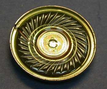
 This 2" long throw speaker is one that I got
with a bunch of others at a swap meet for about $1 each. It comes with
a thick foam gasket.
This 2" long throw speaker is one that I got
with a bunch of others at a swap meet for about $1 each. It comes with
a thick foam gasket.
One of the standard hacks for mounting a speaker in a loco that
otherwise has no room is to mount it on the inside of the cab roof.
With this speaker, it was easiest to mount the front of the speaker to
the roof forming a small enclosure with the "front" being on the inside
of the enclosure. The sound then radiates from the back of the speaker.
This doesn't produce the optimal mount for a speaker, but it is easy. I
just dabbed a little hot glue on two spots on the foam gasket and
pressed it into the nearly flat cab roof. This compressed the foam at
the other sides a little and made a seal all around. It actually sounds
pretty good that way.
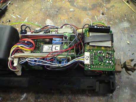
 This is the
installation when it was completed. With the exception of the added
relay, I only soldered two wires, the ones at the speaker tabs.
Everything else was a plug in to the Dallee board or connected to a
screw terminal on the 5490 or 5495.
This is the
installation when it was completed. With the exception of the added
relay, I only soldered two wires, the ones at the speaker tabs.
Everything else was a plug in to the Dallee board or connected to a
screw terminal on the 5490 or 5495.
Samples of Dallee sound can be heard at Dallee Tips.
[ Top ]
DCC, One More Time
After the sound was in and working on the bench, I put it on the
track for a last test and it didn't work. No sound. Also the loco was
running slowly so I assumed that the battery was near flat and there
wasn't enough voltage to pull in the sound power control relay. A quick
charge proved that point, everything worked again.
I charged it overnight and ran it the next day to see what the
battery life was since I had charged it fully less than a week before
and not run it a lot since then. It ran pushing one heavy car for 90
minutes, half it's runtime when the batteries were first installed
eight long years ago. It is suffering from a common problem with NiMH
batteries. After they age, they don't hold a charge very well and their
overall capacity also decreases. I'm going to need new batteries
sometime soon.
The rear hood of the 2060 is nearly empty and it happens to be big
enough to accept a Digitrax DG583S DCC decoder. Further, I just
happened to have one in my DCC box. Since I've done two Battery/RC with
DCC included conversions recently that worked out quite well, a third
one seemed like one path I could take to get out from underneath dead
batteries. The newer DCC decoders, like the DG583S, work much better
with flakey power pickup than the old one that I put in there 10 years
ago and if it is a real problem, I can always either clean the track or
switch it back to battery operation. This hasn't been necessary with
the other dual mode locos that I have done.
There was one complication with this conversion. The relay that I
used to control the power to the Dallee board to reduce the idle
current without sound was problematic. The 5490 doesn't have a blue and
ground wire brought out and I didn't feel like digging into it to bring
them out. Without them, I could not figure out a way to get the relay
to be controlled properly from both the DCC decoder and 5490/5495.
Instead, I elected to eat the idle current of the Dallee board when
muted, which is pretty low anyway, and just use the "E" contact on the
5495 in parallel with F6 on the DCC decoder to mute the sound. As it
turns out, the Dallee board only draws 10 mA when muted and only 33 mA
at with the idle sound running. With the relay, I was trading lower
current with the sound off (0 mA) vs an extra 10 mA to run the relay
when the sound is on. The trade is obvious, jettison the relay.
 This is the schematic of the
conversion. It is pretty straightforward. One DPDT switch determines
where the 5490 gets it's power, either the battery or the track. The
existing SPST power switch becomes unnecessary, but I'll just turn it
on and leave it in place. There is room for these two new switches
behind the rear steps. The DCC decoder is permanently connected to the
track. The DG583S analog converts gracefully so that the decoder can
run from DCC, DC or PWC on the track. The 5490 will run from DCC on the
track as well. It won't work well with low track voltage but if I
should want to use radio control when on DCC powered track, it will
work that way.
This is the schematic of the
conversion. It is pretty straightforward. One DPDT switch determines
where the 5490 gets it's power, either the battery or the track. The
existing SPST power switch becomes unnecessary, but I'll just turn it
on and leave it in place. There is room for these two new switches
behind the rear steps. The DCC decoder is permanently connected to the
track. The DG583S analog converts gracefully so that the decoder can
run from DCC, DC or PWC on the track. The 5490 will run from DCC on the
track as well. It won't work well with low track voltage but if I
should want to use radio control when on DCC powered track, it will
work that way.
The second DPDT switch determines what drives the motor, either the
5490 or the DCC decoder. The Dallee board always runs from the power
source selected for the 5490 and it senses the motor directly no matter
which motor controller is used. The bell, horn and mute functions are
controlled jointly by the 5490/5495 and the DCC decoder. When running
on battery power with no voltage on the track, the DCC decoder does
nothing. If there is DCC on the track, the 5490/5495 can control the
sound too but if the motor switch is set to the DCC side, it won't
control the motor.
The loco will run as a full up battery/RC powered loco with sound, a
full up DCC powered loco with sound, a DC track powered loco but with
flakey sound (the sound won't come on until the track voltage is high
enough) or a radio controlled but track powered loco with either full
voltage DC or DCC on the track. The response to track power is good
enough. The sound system is off when the loco is standing and comes on,
with a little buzz or crackle sound, at just about the same track
voltage as it takes to get the DCC decoder to wake up and analog
convert so the sound comes on just as the loco starts to move. For DC track power, a 9 volt battery could be added in parallel with the 680µF capacitor to allow the sound system to run at idle. However, it would not be possible to turn the sound system off so yet another SPST switch would be needed in series with the battery to be able to disconnect it when desired. The Dallee draws a low enough idle current such that a 9V battery will last quite a while when all it has to do is run the engine idle sounds.
The DCC decoder
response is better with PWC from a 10 amp trackside TE
receiver than with pure DC or a regular power pack but the difference
is not huge. The DG583S has never liked the flavor of PWC made by a
5490 used as a trackside receiver, it'll run in one direction, but not
the other.
Since the 5490 has no directional headlight control capability, I
elected to leave the headlights like they were. They work pretty well
this way as they come on full brightness as soon as the loco starts to
move. They will behave the same when driven from the 5490 or the DCC
decoder.
 There
is little room to add two more DPDT switches unless they are the
"sub-miniature" variety. The Radio Shack 275-626 is a little expensive,
but it fits. However, there were two bosses on the rear deck that had
to be removed. I have no clue what they were for so off they came.
There
is little room to add two more DPDT switches unless they are the
"sub-miniature" variety. The Radio Shack 275-626 is a little expensive,
but it fits. However, there were two bosses on the rear deck that had
to be removed. I have no clue what they were for so off they came.
 Once I had a clear flat spot to mount the DPDT switches, they went in
at the rear corners. I notched the lead weight to clear them and then
added a couple of ounces of lead fishing weights to compensate for the
missing corners. The loco is still a little front heavy due to the
batteries in the front hood.
Once I had a clear flat spot to mount the DPDT switches, they went in
at the rear corners. I notched the lead weight to clear them and then
added a couple of ounces of lead fishing weights to compensate for the
missing corners. The loco is still a little front heavy due to the
batteries in the front hood.
 The DG583S
was mounted above the rear weight. It actually floats sort of free in
the rear hood, jammed up to the top at an angle. It's not going
anywhere and there are enough wires spanning the rear weight so that it
cannot actually electrically touch the weight anyway.
The DG583S
was mounted above the rear weight. It actually floats sort of free in
the rear hood, jammed up to the top at an angle. It's not going
anywhere and there are enough wires spanning the rear weight so that it
cannot actually electrically touch the weight anyway.
I elected to reinstall the sliders in the brick. I managed to find a
pair sitting on my bench and they fit. The springs were there too.
These MIGHT have been the ones that I took out 8 years ago.
Overall, the installation was a little time consuming, but there
were no major difficulties and it all worked. The radio range doesn't
seem to be as good as it was when I initially did the installation, but
it wasn't great before I started the DCC installation either. The DCC
part works perfectly.
I put the engine on a loop of track that had not been cleaned at all
in several months. The track was heavily oxidized. As expected, the
loco ran poorly. It would go several feet and stall. However, running
on the main which had been lightly cleaned in the last week, it ran
without a hitch.
I did notice a pronounced loss of radio control range after this
conversion. The antenna no longer tolerates being connected to the
track when there is DCC signal on the track. Since it tolerated this
before the decoder went it, I assume that the decoder itself has
conducted emission of RF noise that is jamming the radio link. When the
antenna is disconnected from the track, the range doesn't change if the
track is active with DCC or not, but it is not very good, about 10'.
This indicates that the decoder isn't radiating much noise but there is
noise voltage on the track wiring. This was the condition when I first
installed the RX and had the antenna disconnected from the track.
Either I have to find a better antenna configuration or I will have to
put up with reduced range.
With DCC, the loco now runs better than it ever did in any mode. What has changed that
caused me to remove DCC and install battery/RC many years ago? I
believe that there are two factors. The track cleaning method that I
use now is much better and modern DCC decoders have improved
performance (or perhaps that it was the less than stellar performance of
the old DG580L decoder that I used 10 years ago).
During the first time period that I was experimenting with DCC in
this loco, I wasn't using the drywall sander for track cleaning and I
didn't have a track cleaning car adapted to dragging along a drywall
sander pad. The use of the drywall sander has resulted in consistently
cleaner track with far less time and effort expended compared to before.
Other 4 wheel locos like the Bachmann Davenport and the USAT Speeder have poorer pickup
than the 2060 (with it's additional sliders) and they now run well so
that the track condition is very likely much better than it was
before. 10 years ago, I would have never been able to run the Speeder at all.
The other factor is that the DG583S DCC decoder is a FAR better
decoder than the DG580L decoder that I was using in those days. The
DG580L proved to be a dog in the long run. It behaved badly with
intermittent track power and it tended to lose it's mind and just stop
working after particular bouts with dirty track. I've blown up one of
them and scrapped the other two simply because they gave me so much
trouble every time that I tried to use them. The DG583S is vastly more
graceful in it's response to dirty track. It has both + and - terminals
brought out so that adding the storage capacitor would be easy, but
that doesn't seem to be necessary. Higher end Lenz decoders with the
external supercapacitor module are even more graceful when dealing with
dirty track but the DG583S seems to be good enough and it is far less
expensive.
These two factors together make DCC operation quite reliable and
negate the need for battery power altogether. The 2060 has the
batteries in there and they'll stay in there but it is not likely that
I'll actually use them on the GIRR. The batteries always seemed to be
dead when I've tried to use them and I haven't learned to anticipate a
day in advance of when I'd want to use the loco in a battery powered
mode to charge them.
[ Top ] [ Home ] [ Up ] [ Previous Page ] [ Next Page ]
This page has been accessed  times since 22 Jan 1999.
© 1999-2010 George Schreyer
Created Jan 22, 1999
Last Updated September 25, 2010
 11 Jun 10