Thomas and James Tips
[ Home ] [ Up ] [ Previous
Page ] [ Next Page ]
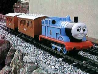 A few years ago, Lionel released a Thomas the
Tank Engine set. Thomas is a British inside cylinder 0-6-0 tank
engine that pulls two coaches, Annie and Clarabel. This set was
based on the Shining Time Station TV series that is probably still
playing on PBS. I would imagine that many large scalers with small
children somehow managed to acquire this set.
A few years ago, Lionel released a Thomas the
Tank Engine set. Thomas is a British inside cylinder 0-6-0 tank
engine that pulls two coaches, Annie and Clarabel. This set was
based on the Shining Time Station TV series that is probably still
playing on PBS. I would imagine that many large scalers with small
children somehow managed to acquire this set.
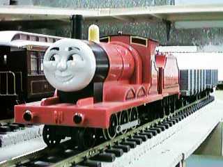 Later, another set containing James the Red Engine
was released. James is an inside cylinder 2-6-0 tender engine of
British design that pulls two 4 axle freight wagons.
Later, another set containing James the Red Engine
was released. James is an inside cylinder 2-6-0 tender engine of
British design that pulls two 4 axle freight wagons.
Neither of these sets is still manufactured but some may still
be around. At the end of James' production run when Lionel exited
the large scale business, these sets were blown out by a discount
store chain, Pic-N-Save, for $49.95 each.
Contents
Power Pickup
Both Thomas and James have six driven wheels, but only four pick
up power. Considering that the brass wheels get dirty fairly fast,
this combination is sure to cause flaky power pickup. If the engine
runs fine in the turns and sputters on the straights, suspect dirty
wheels more than dirty track.
There is a simple modification that can be done to both engines
that materially improves power pickup. The change is to add
contacts to the center driver set.
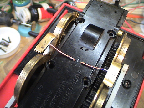
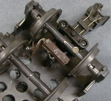
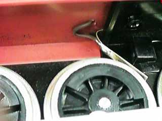 There is no room to add a conventional
power pickup to the center drivers, but it is easy to add a wiper
contact that bears on the center driver tread. On James, it is
straightforward to add a 1/32" thick by 3/32" wide brass contact
strip. The strip is simply clamped between the frame and shell
castings as shown in the photo. A wire is then soldered to the
brass strip and run through a hole drilled in the lower shell and
connected directly to the motor.
There is no room to add a conventional
power pickup to the center drivers, but it is easy to add a wiper
contact that bears on the center driver tread. On James, it is
straightforward to add a 1/32" thick by 3/32" wide brass contact
strip. The strip is simply clamped between the frame and shell
castings as shown in the photo. A wire is then soldered to the
brass strip and run through a hole drilled in the lower shell and
connected directly to the motor.
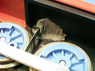 I attached the same
type of contact to Thomas' frame with plumber's epoxy putty. This
particular epoxy is handy because it sets up really fast so that
you don't have to hold it in place for more than about five
minutes. The epoxy also will not stick to your fingers. I modified
Thomas several years ago. After I took this photo recently, I
realized that I probably could have clamped the contact on Thomas
the same way that I did James.
I attached the same
type of contact to Thomas' frame with plumber's epoxy putty. This
particular epoxy is handy because it sets up really fast so that
you don't have to hold it in place for more than about five
minutes. The epoxy also will not stick to your fingers. I modified
Thomas several years ago. After I took this photo recently, I
realized that I probably could have clamped the contact on Thomas
the same way that I did James.
 Even with the center
drivers contributing to power pickup, James was still touchy. I
took a hint from my own Lionel Handcar Tips page
and added a set of sliders. After I got the handcar weighted
sufficiently to deal with the drag of the sliders, they really
improved it's performance such that it would actually run.
Even with the center
drivers contributing to power pickup, James was still touchy. I
took a hint from my own Lionel Handcar Tips page
and added a set of sliders. After I got the handcar weighted
sufficiently to deal with the drag of the sliders, they really
improved it's performance such that it would actually run.
The sliders are simply brass strips soldered to 18 ga copper
wire and secured to the bottom cover of the loco. The copper wire
makes and adequate spring and is easily adjustable.
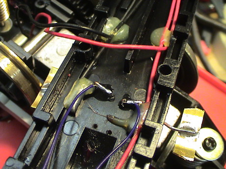 On the inside, the
wire is just bent over and secured with some Zap-A-Gap CA. A wire,
soldered before the application of the CA, leads back to a brass
strip that connects the rear piston contacts.
On the inside, the
wire is just bent over and secured with some Zap-A-Gap CA. A wire,
soldered before the application of the CA, leads back to a brass
strip that connects the rear piston contacts.
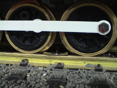 The sliders fit right
between the center and rear drivers and are not too visually
obtrusive. The improvement in power pickup was quite pronounced.
James used to have a tendency to fail to pick up power after it was
stopped and to stutter on turnouts. These tendencies seem to have
gone away.
The sliders fit right
between the center and rear drivers and are not too visually
obtrusive. The improvement in power pickup was quite pronounced.
James used to have a tendency to fail to pick up power after it was
stopped and to stutter on turnouts. These tendencies seem to have
gone away.
[ Top ]
Disassembly
Both Thomas and James are fairly easy to get apart for
lubrication or modification. There are only a couple of
cautions.
The brick covers come off with six screws. The only caution is
to be careful of the spring loaded power pickup contacts. If you
just lift the lower brick cover, they will pop out and are easy to
loose. As you are lifting the cover, place your fingers near each
contact and as the contact moves beyond the wheel face, hold it
with your finger. You can then gently relieve the pressure on the
contacts. Some of them may fall out, but at least the springs won't
eject them across the room. Inspect the springs, they should be
silver colored. If they are brown, they have been overheated and
have lost their strength. Those springs won't work very well and
should be replaced.
Thomas's body shell comes off with seven screws. There are three
on each side and one in front. Note that the front one is shorter
than the others. If you put one of the longer screws back in that
spot, you will break off the mounting post when the screw bottoms
out. The shell may take a little persuasion to release at the
smokebox joint. Just gently lift and wiggle the shell and it will
pop off.
James comes apart in much the same fashion except that the screw
in front is obscured by the pilot truck which must be removed to
gain access to the screw.
[ Top ]
Lubrication
Both Thomas and James use a small vertically mounted can motor
that drives the rear axle through a worm gear. Power is transmitted
to the other two axles by an external spur gear train similar to
that used on many Lionel "O" scale locos. Lubrication of the worm
should be done with heavy gear grease or oil. Lubrication of the
spur gear train is a little more problematic because lubricants
applied there will attract dirt and excessive lubrication will get
on the backs of the wheels and interfere with the power contacts. I
use a very small amount of LGB 50019 oil on the external gearing as
this oil is effective and doesn't seem to foul the electrical
contacts.
The mechanism that runs the moving eyes on the smoke box cover
can be lubricated, if necessary, with gear grease.
After many years, the grease that Lionel used can dry out and
become hard. If some grease hardens in a gear, it can literally
plug the gear teeth and result in a repeating bind in the
mechanism. This can happen on any gear in the loco. If this
happens, the solution is to pick out the hardened grease from all
the teeth with a small pick or screwdriver and relubricate the
loco.
[ Top ]
Couplers
James resides at the Geologically
Improbable Railroad, Mountain Division and so he needed LGB
knuckle couplers. It turned out to be straightforward to mount them
in place of the supplied hook and loop couplers.
Thomas runs on my outdoor version of the Geologically Improbable Railroad so he
needed Kadee couplers. #831's mount with little difficulty.
[ Top ]
Adding Weight
Both engines are very light. They will pull their assigned two
car consist on level track fine, but add a car or hit a moderate
grade and both will spin their drivers. I added 12 to 16 oz of lead
to the inside of both engines centered above the drivers.
James has a three axle tender that is very light and would
derail under almost any kind of a load beyond his two cars. I glued
4 oz of lead under the tender floor and the tender started to
behave itself.
Neither of these sets have metal wheels yet. I'm not sure why I
haven't changed them.
[ Top ]
Sound Installation in James
Neither Thomas or James come equipped with a sound system, and
considering how little these engines are worth, it doesn't seem
reasonable to spend the money to add one. However, after I added a
Sierra to one of my Shays, its old Bachmann sound board became
available. Since it could run off a battery for a long time, it
seemed reasonable to install in James which still had plastic
wheels.
 There is little room
in Thomas for a sound board and speaker, but James has a large
nearly empty tender that is easily big enough. The tender shell is
attached with two screws, one under the rear coupler and the other
also secures the drawbar.
There is little room
in Thomas for a sound board and speaker, but James has a large
nearly empty tender that is easily big enough. The tender shell is
attached with two screws, one under the rear coupler and the other
also secures the drawbar.
 A 3"
speaker fits easily on the flat floor. A bunch of holes drilled
through the floor lets the sound out. The Bachmann sound board was
recovered from a defunct R/C Big Hauler. To make the board fit
better in the Shay, it had been literally hacked in half. All the
sound circuitry is on the rear third of the board so all that is
necessary is to cut a trace leading down each side of the board
past the sound circuitry and then to physically cut the rest of the
board off. I left some of the motor control circuit behind just
because it was easier to cut right through the motor controller IC.
The rest of the board is mounted to the back of the speaker magnet
with foam mounting tape. The battery is stuck to the side of the
speaker with foam mounting tape.
A 3"
speaker fits easily on the flat floor. A bunch of holes drilled
through the floor lets the sound out. The Bachmann sound board was
recovered from a defunct R/C Big Hauler. To make the board fit
better in the Shay, it had been literally hacked in half. All the
sound circuitry is on the rear third of the board so all that is
necessary is to cut a trace leading down each side of the board
past the sound circuitry and then to physically cut the rest of the
board off. I left some of the motor control circuit behind just
because it was easier to cut right through the motor controller IC.
The rest of the board is mounted to the back of the speaker magnet
with foam mounting tape. The battery is stuck to the side of the
speaker with foam mounting tape.
 The sound
switch is a reed switch left over from a PH Hobbies sound board
installation sometime in the dark distant past. The switch is stuck
to an existing bracket in front of the rear axle. Two small high
energy magnets are attached to the rear axle with Zap CA.
The sound
switch is a reed switch left over from a PH Hobbies sound board
installation sometime in the dark distant past. The switch is stuck
to an existing bracket in front of the rear axle. Two small high
energy magnets are attached to the rear axle with Zap CA.
This cheap and dirty installation didn't cost me a dime out of
pocket as all the parts were already available as left overs from
previous sound system installations. The sound is typically not
great, but then considering the cost, it is acceptable.
[ Top ]
Battery and Radio Control Installation in
Thomas
Thomas is a favorite now of the nephews, but it often tended to
disappoint them because it just didn't run all that well. Even with
the power pickup improvements described above, Thomas was never an
outstanding performer on track power. There just aren't enough
pickup wheels and the brass wheels tend to get dirty quickly. Just
as I have done on several other locos, if they are too small to
pick up power well, they get converted to battery power with radio
control. Thomas got converted to battery-r/c using the tri-modal
wiring that I have described elsewhere. I choose to
use a 75 MHz CRE-55491 receiver (because I had one handy) and a 12
cell NiCad pack (because I got it for $12 at a local ham radio swap
meet). All the rest of the parts were retrieved from my parts
stock.
 This is the schematic
of I used to wire Thomas. It is my standard "tri-modal" circuit. It
takes just a little more wiring than the dead simple versions, but
depending on how the switches are set, it will still run from
straight track power, or RC with track power, or RC with the
internal battery. The charge jack is arranged to charge properly
from a 24 VDC source.
This is the schematic
of I used to wire Thomas. It is my standard "tri-modal" circuit. It
takes just a little more wiring than the dead simple versions, but
depending on how the switches are set, it will still run from
straight track power, or RC with track power, or RC with the
internal battery. The charge jack is arranged to charge properly
from a 24 VDC source.
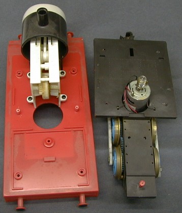
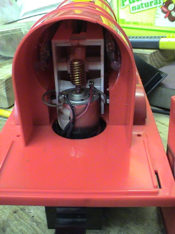
Thomas consists of three major parts, the motor brick and
sub-frame, the frame and the shell (not shown in this view). The
first order of business in any RC installation is to determine
where to put all the stuff. This takes some thought. I like to
either put everything on the frame or everything in the shell to
minimize the number of wires going between the frame and the shell.
It was pretty clear that in this installation, most of the stuff
would go into the shell. Thomas's eyeball activation mechanism
takes up the entire boiler volume so everything would have to go
into the saddle tanks or the cab.
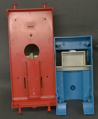 The saddle tanks
were too small to hold the battery packs that I had, but they would
fit nicely crosswise in the cab with the cab interior view block
removed. The region inside the tender could hold the receiver. The
switches and charge jack were a problem.
The saddle tanks
were too small to hold the battery packs that I had, but they would
fit nicely crosswise in the cab with the cab interior view block
removed. The region inside the tender could hold the receiver. The
switches and charge jack were a problem.
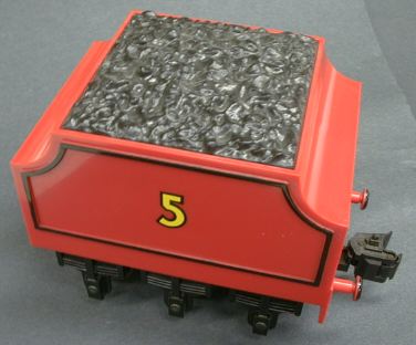
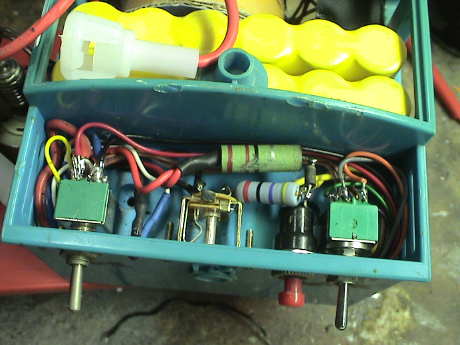
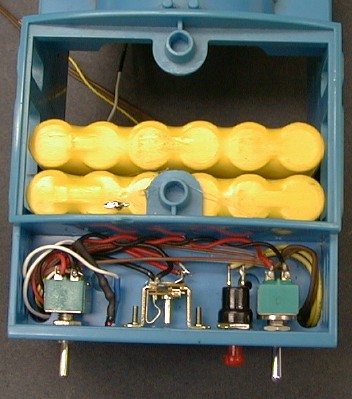 Thomas's coal load
is easily removed and the region under it was just right to hold
the five items that had to fit there, two power control switches,
the code set button, the charge jack and an indicator LED to make
programming the receiver from outside the loco practical. The LED
is wired as the rear headlight. Thomas doesn't have a front
headlight and I choose not to install one.
Thomas's coal load
is easily removed and the region under it was just right to hold
the five items that had to fit there, two power control switches,
the code set button, the charge jack and an indicator LED to make
programming the receiver from outside the loco practical. The LED
is wired as the rear headlight. Thomas doesn't have a front
headlight and I choose not to install one.
With the batteries installed as shown, Thomas' weight
distribution is wrong. With power abruptly applied, Thomas would do
wheelies. I added 4 oz of lead under the front wheel skirts and
inside the front of the saddle tanks to help balance the weight of
the batteries.
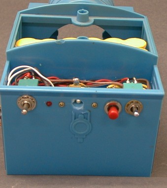 All this hardware hanging off
the back of Thomas isn't particularly attractive, but they were
easy to install and access in that location. The back side of the
coal load and its mounting posts must be gouged off but this can't
seen from the outside and the posts weren't used anyway.
All this hardware hanging off
the back of Thomas isn't particularly attractive, but they were
easy to install and access in that location. The back side of the
coal load and its mounting posts must be gouged off but this can't
seen from the outside and the posts weren't used anyway.
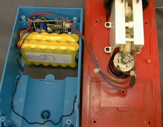 The receiver is simply mashed back in the
tender. I didn't use the adaptor board because there wasn't room.
The shrink tubing over the wires soldered to the pins is sufficient
to hold the receiver in place against the battery.
The receiver is simply mashed back in the
tender. I didn't use the adaptor board because there wasn't room.
The shrink tubing over the wires soldered to the pins is sufficient
to hold the receiver in place against the battery.
Now Thomas runs quite smoothly and it doesn't care what
condition the track or wheels are in. The next time that the
nephews visit, they'll have Thomas to run until the battery goes
down. Then if they want to run it some more, they can switch it to
track power and keep going provided some hesitation doesn't bother
them.
[ Top ]
DCC Installation in James
James resides at the GIRR Mountain Division which has recently
been converted to DCC. James was the last loco to be converted. I
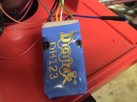
didn't want to spend a lot of money on a decoder so I attempted to
use an HO sized decoder, a Digitrax DH123D which costs only $16. I
knew that James's stall current was a little high for this decoder
but it's running current is well within the DH123's capability. I
have used the DH123 successfully in a 2nd generation Big Hauler and
a Lionel Handcar.
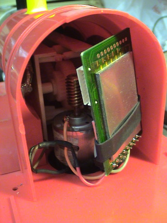
 There is enough
room inside James for a small decoder. The cab comes off with just
two screws revealing all that is necessary to install a decoder,
especially considering that there are no accessory functions
used.
There is enough
room inside James for a small decoder. The cab comes off with just
two screws revealing all that is necessary to install a decoder,
especially considering that there are no accessory functions
used.
 The DH123D went in
fine and seemed to run ok for awhile. But after just one lap
around, James stopped inside a tunnel. When I got to it, it was
smoking. James was indeed a little too much for this decoder. It is
clearly burned up.
The DH123D went in
fine and seemed to run ok for awhile. But after just one lap
around, James stopped inside a tunnel. When I got to it, it was
smoking. James was indeed a little too much for this decoder. It is
clearly burned up.
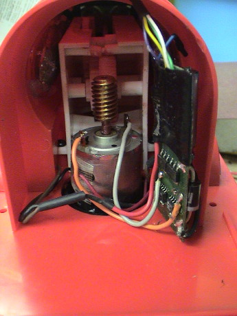 I recovered an
MRC AD320 decoder from an Aristo Classic Railbus which got a
Digitrax DG583S to replace the AD320. The AD320 has just 4
functions and I needed one more so I used the, now surplus, AD320
in James. It just fit next to the motor. As expected, the AD320
makes quite a bit of noise as heard in this H.264 video clip. However it does run.
I recovered an
MRC AD320 decoder from an Aristo Classic Railbus which got a
Digitrax DG583S to replace the AD320. The AD320 has just 4
functions and I needed one more so I used the, now surplus, AD320
in James. It just fit next to the motor. As expected, the AD320
makes quite a bit of noise as heard in this H.264 video clip. However it does run.
 Eventually, the AD320
burnt up in James. The heat load was apparently too high as the
circuit board literally came apart. I put analog voltage on the
track for awhile to do some testing on another loco and James was
sitting on powered track. It didn't move, but apparently the AD320
couldn't handle it and it burnt. I smelled the burnt smell but I
didn't know where it came from. It was months later that I tried to
run James again and it just didn't work. I took the decoder out and
it was visually obvious that it was toast.
Eventually, the AD320
burnt up in James. The heat load was apparently too high as the
circuit board literally came apart. I put analog voltage on the
track for awhile to do some testing on another loco and James was
sitting on powered track. It didn't move, but apparently the AD320
couldn't handle it and it burnt. I smelled the burnt smell but I
didn't know where it came from. It was months later that I tried to
run James again and it just didn't work. I took the decoder out and
it was visually obvious that it was toast.
I had a spare Digitrax DG583S so I put it in. It was a simple 4
wire screw terminal installation using the wires that I cut off the
failed AD320. This decoder worked fine and now James runs better
than it ever did.
[ Top ]
Sound Installation in Thomas
A Bachmann Shay at the GIRR Mountain Division surrendered it's
analog sound board when a QSI DCC decoder was installed. The QSI
provides excellent sound and the analog board was no longer needed.
The Shay also surrendered it's "interface board" which has nothing
on it except a bridge rectifier. These parts went in the sound
parts box until I elected to install it in Thomas. This particular
analog sound board had started life in an RC Big Hauler that I
bought from a neighbor kid for parts.
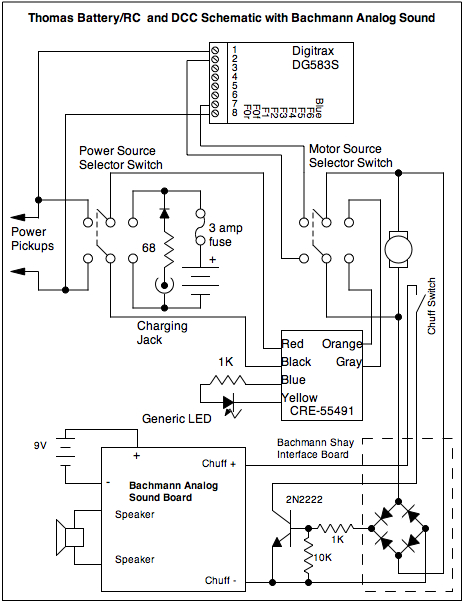
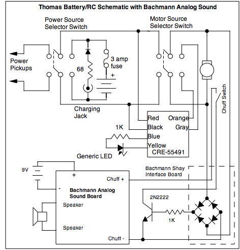 This
is the diagram that I used to do the install in Thomas. The
previous "tri-modal" battery/track/RC wiring was not changed. The
Bachmann analog sound board runs from a 9V battery that will last
for years. The board had also been modified with a circuit to stop
the continuous chuff when it was in the Shay and that circuit was
retained as well.
This
is the diagram that I used to do the install in Thomas. The
previous "tri-modal" battery/track/RC wiring was not changed. The
Bachmann analog sound board runs from a 9V battery that will last
for years. The board had also been modified with a circuit to stop
the continuous chuff when it was in the Shay and that circuit was
retained as well.
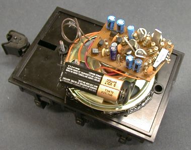
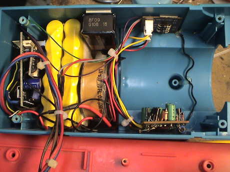
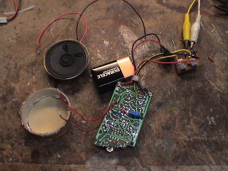 These are most of
the parts needed for the sound installation. The sound board was
later trimmed in size to make if fit better. The speaker was in my
parts box, it was the largest that would easily fit. I made an
enclosure by cutting off the bottom of a caulking gun tube and hot
gluing a piece of cardboard over the end to make a small enclosure.
Not shown is the reed switch and magnets that were used to make the
chuff switch.
These are most of
the parts needed for the sound installation. The sound board was
later trimmed in size to make if fit better. The speaker was in my
parts box, it was the largest that would easily fit. I made an
enclosure by cutting off the bottom of a caulking gun tube and hot
gluing a piece of cardboard over the end to make a small enclosure.
Not shown is the reed switch and magnets that were used to make the
chuff switch.
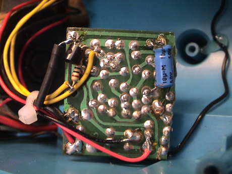 This
is the bottom of the sound board after it was hacked to size. The
very last row of solder pads on the right side are not needed, but
the board was small enough at this point so I didn't trim any
further. The stuff that is gone is all the motor controller
circuitry from the RC Big Hauler. The transistor and resistor in
the upper left is the chuff cutoff switch. The red and black wires
at the lower right are the speaker leads. A diagram of the
connection points to this board can be found at my Better Bachmann Sound for Under a
Buck page.
This
is the bottom of the sound board after it was hacked to size. The
very last row of solder pads on the right side are not needed, but
the board was small enough at this point so I didn't trim any
further. The stuff that is gone is all the motor controller
circuitry from the RC Big Hauler. The transistor and resistor in
the upper left is the chuff cutoff switch. The red and black wires
at the lower right are the speaker leads. A diagram of the
connection points to this board can be found at my Better Bachmann Sound for Under a
Buck page.
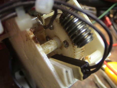 There
wasn't room to put chuff magnets and a reed switch in or on the
brick so I attached them to Thomas's eye movement mechanism
instead. This gear is apparently the same size as the one on the
rear driver because it turns at the same rate as the driving
wheels. I cleaned the side of the gear off with alcohol and
attached four small high energy magnets to the side of the gear
with Zap-A-Gap CA. The chuff reed switch was recovered from my
sound system parts box. I think that it probably came with a PH
Hobbies sound system. The switch is mounted with several layers of
foam mounting tape.
There
wasn't room to put chuff magnets and a reed switch in or on the
brick so I attached them to Thomas's eye movement mechanism
instead. This gear is apparently the same size as the one on the
rear driver because it turns at the same rate as the driving
wheels. I cleaned the side of the gear off with alcohol and
attached four small high energy magnets to the side of the gear
with Zap-A-Gap CA. The chuff reed switch was recovered from my
sound system parts box. I think that it probably came with a PH
Hobbies sound system. The switch is mounted with several layers of
foam mounting tape.
 The speaker
in a home made cardboard enclosure is mounted with foam tape
against the traction battery pack. The 9V battery for the sound
system is mounted on the inside of the cab, also with foam tape.
The Shay interface board is mounted to the inside of a side tank
with foam tape. The sound board itself is mounted with hot
glue.
The speaker
in a home made cardboard enclosure is mounted with foam tape
against the traction battery pack. The 9V battery for the sound
system is mounted on the inside of the cab, also with foam tape.
The Shay interface board is mounted to the inside of a side tank
with foam tape. The sound board itself is mounted with hot
glue.
For what it cost me, $zip.zero out of pocket, this installation
worked pretty well.
[ Top ]
DCC Installation in Thomas
 Thomas was my very last loco that
hadn't been converted to DCC. It got the battery conversion because
it was unreliable on track power unless the track was reasonably
clean. However, with the newer DCC decoders, locos run a little
better on DCC than they do on straight up track power, especially
ones with variable contact resistance like Thomas has.
Thomas was my very last loco that
hadn't been converted to DCC. It got the battery conversion because
it was unreliable on track power unless the track was reasonably
clean. However, with the newer DCC decoders, locos run a little
better on DCC than they do on straight up track power, especially
ones with variable contact resistance like Thomas has.
There are decoders especially configured to run on backup super
capacitors for a few seconds that pretty much eliminate track power
problems, Lenz makes the best ones now. However, they are expensive
and the super capacitors needed to make it immune to dirty track
are still pretty large. There is simply no room left in Thomas for
that. I used a DG583S because they work very well.
This conversion is less complicated than the other three battery
powered locos to which I have added DCC. Information on these can
be found at my LGB 2060
Tips , FA Tips and Center Cab Tips pages.
The loco already had sound of sorts that I didn't have to touch.
It also already had the DPDT switches installed. There is no
lighting, sound sound triggers or any other need for decoder
accessory functions. The decoder is simply inserted into the track
power path to the motor. The loco will still operate on straight up
DC track power but via the analog conversion capability of the
DG583S decoder which analog converts quite well.
Thomas still has four operating modes.
- Straight up battery/RC
- Track powered (DC, PWC or DCC) RC
- Straight up DCC
- DC track power via analog conversion of the DCC decoder. It
will sometimes work with PWC on the track, but the DCC decoders
sometimes become confused when they see PWC and can't figure out
what to do.
|
The one mode that I lose is with the power switch set to the
battery and the motor switch set to the DCC decoder. This will do
nothing except slowly drain the battery. These switch positions
used to connect the battery directly to the motor. This mode isn't
very useful except as a quick check that the battery has some
charge in it and there are other ways to test that.
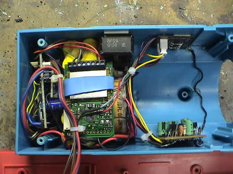 The DG583S
decoder is mounted on the bottom of the battery pack and wired up
through an existing hole to the switches on top.
The DG583S
decoder is mounted on the bottom of the battery pack and wired up
through an existing hole to the switches on top.
 The only change
on the topside was to remove a pair of wires that went from the
left switch to the right one. This was the pair that connected the
power source switch to the motor selector switch.
The only change
on the topside was to remove a pair of wires that went from the
left switch to the right one. This was the pair that connected the
power source switch to the motor selector switch.
The red and black decoder wires were wired to the power source
switch and the orange and gray motor wires were wired to the motor
selector switch. That was it for the wiring.
The two resistors and a diode that are in this photo and not in
the previous one of this same area are the charge current limiting
resistors that used to to be in the charger cable. The rewiring was
done some time ago so that the loco would charge properly from
straight 24 VDC.
I did add a 10K resistor to the sound switch circuit to fully
drag the base of the control transistor to ground when no motor
drive was present. The switch had a tendency to leak sometimes and
the sound board would crackle softly. That is now fixed.
After the mod, Thomas ran right off. There was a bit more dried
grease on the drive gear for the eyeball assembly that interacted
with the BEMF decoder as a repeating bind. I cleaned the grease
from the gear and that went away. While I was testing Thomas on the
track, it ran quite smoothly until it started making a horrible
racket when running forward. It was quiet in reverse. I knew from
experience that Thomas had eaten another drive gear. Sure enough,
the plastic gear on the rear axle had a worn spot. It quickly got
worse to the point that the gear failed completely.
Lionel is not stocking most parts for obsolete locos. They have
sold their inventory of older parts to North Lima Trainworks. They
did not have the whole axle assembly though, only the drive wheels
with the integrated gear for the gear train to the other driver
axles. It turns out that Lionel thought that they did have the axle
assemblies for $8.50 each. I ordered two but I got a phone call.
They were out of stock and weren't going to get anymore. They did
have one used one in good condition. They gave me the part for free
but I still had to pay shipping. Anyway, it arrived, it was
installed and Thomas lives again.
It ran on track that hadn't been cleaned at all in two or three
weeks although it sputtered some and it derailed a many times on
ivy leaves and stems. I noticed that when it hit a bad spot and
then found power again, it would start up so fast that it would do
wheelies and sometimes derail. The weight of the batteries is
behind the rear driver which upsets Thomas's balance. I had never
noticed this before because the TE RC system has some built in
momentum and I never had abrupt power changes. This jerks were
going to be hard on the gears and may have contributed to the rapid
failure of an already worn out gear. I added a little momentum into
the DCC decoder and that was patched. Some more weight added
forward inside the shell actually fixed that problem.
Now, on reasonably clean track, Thomas runs fine on DCC and it
still has the radio control gear and batteries as well. It ran for
hours on end at the November display layout at the South Coast
Botanic Gardens, both on it's old batteries (got 2.5 hours of run
time) an on DC on the display track. For display layouts, Thomas
sucks the little (and big) kids right in.
[ Top ] [ Home ] [ Up ] [
Previous Page ] [ Next Page ]
This page has been accessed  times since 31 Jan 1998.
© 1998-2009 George Schreyer
Created Jan 31, 1998
Last Updated November 13, 2009
 24 May 09
 22 Dec 08