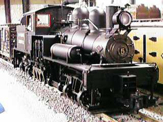
 The Bachmann Shay
is an excellent engine that has been very well received. It runs
very smoothly, pulls as well as any Large Scale engine and is very
well detailed. Further, it is 1:20.3 scale which is correct for the
3' gauge of the prototype.
The Bachmann Shay
is an excellent engine that has been very well received. It runs
very smoothly, pulls as well as any Large Scale engine and is very
well detailed. Further, it is 1:20.3 scale which is correct for the
3' gauge of the prototype.The Bachmann Shay
is an excellent engine that has been very well received. It runs
very smoothly, pulls as well as any Large Scale engine and is very
well detailed. Further, it is 1:20.3 scale which is correct for the
3' gauge of the prototype.
However, there is always something that can be improved on any engine. The Shay is no exception. This page documents some of the little things about the Shay that I have discovered that might be of use to other Large Scalers.
 2 Oct 08 13 Oct
09 13 Oct 09
2 Oct 08 13 Oct
09 13 Oct 09The video tape that comes with the engine has detailed instructions about lubricating the engine. However, it doesn't tell you everything.
The Shay comes with a jewelers screwdriver to take out the screws on the bottoms of the trucks. This screwdriver is totally inadequate for the job. Some Chinese assembler used a MUCH bigger screwdriver to install the screws and getting them out the first time can be a challenge.
Get a REALLY GOOD #1 Phillips head screwdriver to start with. Then work a finger around the back of the truck behind the screw that you are working on to support the truck and use all the force you can muster to press the screwdriver into the screw head before trying to dislodge it. I've done 2 Shays and each of the 32 screws was a challenge to get loose, but I didn't mess up any of them. When you reinsert them, do not tighten them past snug.
Get rid of the white grease that Bachmann uses and replace it with a high quality gear grease such as LGB 51020 gear grease.
The Shay is a big engine. Even though the prototype was a fairly small locomotive, due to its scale it is taller and wider than most other Large Scale engines. This can cause problems on layouts that have tight clearances, like mine for instance.
The Shay will run on 2' radius track and doesn't look too bad doing it. Shay's were designed to run on twisting track so they are at home on tight curves. However, the Bachmann Shay is intolerant of poorly leveled track and will derail each and every time on bad track. If you experience derailment problems at particular parts of your railroad, get a small level and check the track every 6" or so through that area. If the track is out of level by more than half a bubble, fix it.
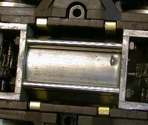
The Shay is 5" wide over the widest protrusions and 21" long over the end steps. On 2' radius curves the engine overhangs 4-1/8" from the track centerline on the inside and 3-3/4" on the outside. With the standard stack, the engine stands 7-7/8" from the railhead. With the modified stack shown in the lead photo, the tallest point is the whistle which is 7" above the railhead.
The modified stack came from a defunct R/C Big Hauler. It required a little filing to make it fit, but it looks and works fine. There are also after market metal oil stacks now available that are designed to accept an LGB smoke unit.
If the whistle is still too tall for you, as it was for me, then it is fairly easy to fix. I pulled the handrail standoffs, whistle and pops from the steam dome and then pulled off the dome. I then cut a 1/4" section out of the middle of the dome above the holes for the handrail standoffs and then glued it back together. I filed it to fit, painted it to match (Engine Black) and then put it back in place and reinstalled the standoffs, whistle and pops.
There are other clearance problems with the Shay. The brake beams hang very low and WILL hang up on LGB screw clamp track connectors. The brake beams and end steps will barely clear LGB and Aristo turnout motors.
The cab is so wide that it will only clear the lamp stands on LGB 1056 uncoupling tracks when the lamp is rotated parallel to the track.
[ Top ]The Shay is equipped with flickering ashpan and firebox lights. These are simulated with LEDs. The red and yellow ones both flicker, the red ones stay on about 2/3 of the time and the yellow ones 1/3 of the time. The effect is pretty good while it is going, but the engine has to be moving fairly fast, way faster than the prototypical maximum 10-12 mph, before the flickering will start. The speed that the flickering starts is somewhat dependent on your power pack. If you use pure DC, you might not see them start flickering at all. They work a little better with Aristo PWC power, but still not real well.
My thanks to Garry Paine for taking the time to trace out the circuit. The top part consists of an adjustable regulator set to 9 volts and a cab light control circuit. The bottom part of the circuit is the multivibrator which flickers the LEDs. It will light the red LEDs at lower than 9 volts on the internal regulated bus, but does not start to flicker until a full 9 volts is reached. Due to the overhead of the LM317 regulator and the bridge rectifier, about 12 volts is needed on the track to get the circuit going. At 12 volts, the Shay is really trucking so its hard to see the lights anyway. If you run at anything like prototypical speeds, you'll never get going that fast.
I added a 50 micro farad capacitor to the output of the bridge rectifier that will charge off any peaks of power that might be applied to the track so that the regulator has the best chance of working at lower average input voltage. Since I use an Aristo Train Engineer which puts out full voltage pulses even at very low speed, the addition of this capacitor causes the cab light, headlights and the flickering lights to come full on just as the engine starts to move. With pure DC power there will be no noticeable improvement.
The downside of this change is that the cab light starts to flicker heavily. The cab light is driven by a circuit that will shut off the cab light when the input voltage to the regulator IC gets too high. I personally don't seen the advantage of this "feature" so I disabled it by cutting a lead on the 1.8K resistor (labeled R9 on the circuit board). This turns on the cab light control transistor all the time.
After this change, I found that the cab light was too bright, it shines as bright as the headlight. I added 100 ohms in series with the cab light to tone it down. If you want to reduce the intensity of the cab light, unsolder one of the wires labeled L1 and add a 100 ohm resistor in series with the wire.
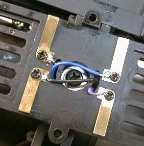
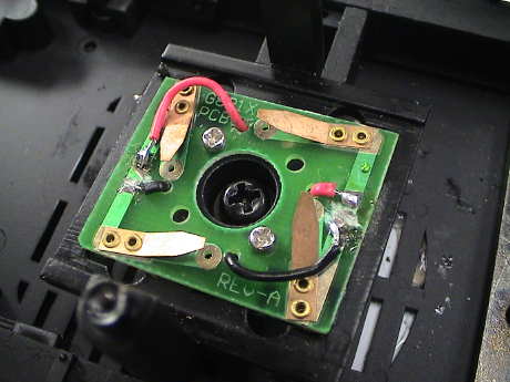
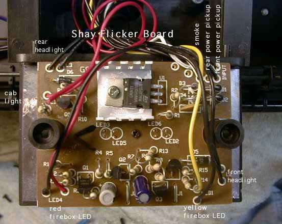 If you decide to do any other wiring
on the flicker board, locating the wires can be somewhat of a pain.
The following photo shows what function each wire pair provides.
This photo is of a 1st run Ely Thomas #5 Shay, newer models may or
may not be the same.
If you decide to do any other wiring
on the flicker board, locating the wires can be somewhat of a pain.
The following photo shows what function each wire pair provides.
This photo is of a 1st run Ely Thomas #5 Shay, newer models may or
may not be the same.
While I was doing the DCC conversion of the 2nd Shay (also a first run unit) I noticed that the annotation for the headlights is backwards. The wires marked for the rear go to the front headlight. The ones marked for the front go to the rear.
The Shay contains a standard Bachmann smoke unit, which means that it'll burn up in a short second if you let it run dry. This is a problem as you can't put more than a few drops in the smoke generator and it smokes so strongly that the smoke fluid runs out in a couple of minutes.
If the smoker works, but smokes weakly, it may be possible to improve the smoke output at zero cost, see my Smoke Tips page for details. The downside is that it may go through smoke fluid faster and be even more likely to burn up if it runs dry.
One of mine burned up so I changed it out with an LGB unit which works much better. It doesn't generate as much smoke but it generates enough and it'll run for 15 minutes or more.
Gary Cook sent me some instructions as to how he changed out his, thanks Gary. Here's my slant on the modification after doing one myself.
The plan is to use an LGB 5 volt replacement smoke element and a common 5 volt regulator circuit. All this stuff can be mounted in the location of the existing smoke element.
 The circuit is
straightforward. A bridge rectifier converts the track voltage to a
constant polarity. The filter capacitor charges up to the peak
track voltage to provide the maximum input to the regulator even at
low track voltages. The regulator drops whatever voltage is
available to 5 volts to drive the smoke unit.
The circuit is
straightforward. A bridge rectifier converts the track voltage to a
constant polarity. The filter capacitor charges up to the peak
track voltage to provide the maximum input to the regulator even at
low track voltages. The regulator drops whatever voltage is
available to 5 volts to drive the smoke unit.
The capacitor is optional. If you use pure DC track power, it won't have any effect. The track voltage will have to be above about 8 volts before the smoke generator will start to work well. Unfortunately, at 8 volts, the Shay is moving right along. If you use Aristo PWC, the capacitor will charge to the peaks (18 to 22 volts depending on the input voltage to your TE receiver) and the regulator will have enough average input voltage to work as soon as the Shay gets moving at all. You'll get full intensity smoke at almost any speed.
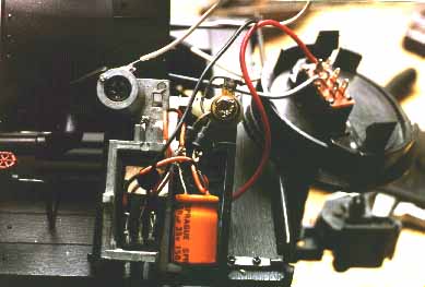 This is a
photo of my installation. The diodes are underneath the filter
capacitor. Any parts that could move around were secured with hot
glue.
This is a
photo of my installation. The diodes are underneath the filter
capacitor. Any parts that could move around were secured with hot
glue.
LGB smoke units like about 10 to 15 drops of smoke fluid. Less means less smoke duration. More will prevent the smoke unit from getting hot enough to smoke well, it'll just sputter.
The Shay is delivered to accept a sound system. There is a chuff switch in the engine assembly that closes 3 times per crank turn (half the prototypical rate). This switch is brought back to the tender for easy access on a pair of yellow wires. In the tender there is also a small printed circuit board with a bridge rectifier on it that supplies constant polarity power a sound system. This board is nearly useless and is usually scrapped during sound system installation. There is also a pocket for mounting a speaker.
There are two track powered digital sound systems available now for the Shay. They are available from Phoenix and Soundtraxx. All of the rest of them will not operate when the track power goes to zero.
After I got my Shays, I didn't want to wait for a custom sound system to be released, and because I am fundamentally cheap, I literally hacked the sound board out an old R/C Big Hauler and installed it into the tender. Since I retained the 9 volt battery, I had only to hook the old sound board up to the yellow wires and install the speaker from the old Big Hauler in the tender floor. I also installed a shutoff switch under the water hatch. I used one of the old slide switches from the R/C Big Hauler. This sound system isn't the greatest in the world, but it is better than stealth mode. See Better Bachmann Sound for more information about using and improving the Bachmann sound system.
There is one important thing to note about the chuff switch which will affect any of the sound systems. The switch is mounted behind the engine assembly and runs off the piston rods. The rods are driven from the crank which is in turn driven by only the front truck. The shaft to the rear truck freewheels. When you slip off the square shaft to the front truck to lubricate it, there is a 50% chance that you'll get it back on 90 degrees off the orientation that it was before you removed the shaft. You'll know that you got it wrong if the engine chuff rate becomes unsteady when the front truck is in a tight right turn. A universal joint provides uneven rotational speed transfer when it is off axis. If the two joints on the front shaft are oriented correctly with respect to each other, these speed transfer errors will cancel. If it is wrong, they will add. This will result in uneven crank speed and therefore uneven chuff switch closures. If you hear uneven chuffs, simply pull out the front shaft, rotate it 90 degrees and reinsert it.
[ Top ]"Chili" John Pritchard offers these instructions for installing a Kadee 821 on the Shay.
 The Kadee 821 couplers can be easily
installed on the Shay. The shallow depth of the box makes them
ideal for use in the existing coupler pockets. But first, the end
beams have to be modified and the coupler boxes lowered so that the
couplers end up at the right height.
The Kadee 821 couplers can be easily
installed on the Shay. The shallow depth of the box makes them
ideal for use in the existing coupler pockets. But first, the end
beams have to be modified and the coupler boxes lowered so that the
couplers end up at the right height.
 Truck mounting couplers is
easy. For the LGB Knuckle, just remove the stock coupler and
install the LGB Knuckle. It will look ugly as sin but it will also
work fine on 2' radius curves.
Truck mounting couplers is
easy. For the LGB Knuckle, just remove the stock coupler and
install the LGB Knuckle. It will look ugly as sin but it will also
work fine on 2' radius curves.
 For the Kadee coupler,
remove the original coupler, cut off the end of the coupler
mounting tang and screw on a Kadee #831 using the original screw
and the original hole. Mounting the coupler this way leaves a lot
to be desired from a visual viewpoint, but it will work fine on 2'
radius curves.
For the Kadee coupler,
remove the original coupler, cut off the end of the coupler
mounting tang and screw on a Kadee #831 using the original screw
and the original hole. Mounting the coupler this way leaves a lot
to be desired from a visual viewpoint, but it will work fine on 2'
radius curves.
Dave Goodson has offered these instructions for modifying the valve gear so that it will shift itself from forward to reverse depending on the direction of motion of the engine. Dave supplied the instructions, I supplied the pictures that I took when I did this modification myself following his instructions.
Dave Goodson writes:
To modify your Bachmann Shay to have functional reverse linkage that "floats" in and out with direction, proceed as follows:
 Remove engine from locomotive. This is accomplished by removing the
lower firebox cover (2 screws), disconnecting drive shafts, and
removing two Phillips head screws between the cylinders. Rotate two
"lugs" inside firebox until they align with the slots, and
carefully work the engine away from the chassis. Pull pin connected
to link shaft arm out of cab floor.
Remove engine from locomotive. This is accomplished by removing the
lower firebox cover (2 screws), disconnecting drive shafts, and
removing two Phillips head screws between the cylinders. Rotate two
"lugs" inside firebox until they align with the slots, and
carefully work the engine away from the chassis. Pull pin connected
to link shaft arm out of cab floor.
Next, remove the pin that went into the cab floor from the shaft completely. It will not be reused. (editor's note) There doesn't seem to be an easy way to remove this pin so I just cut it off.
Work the linkage "in" and "out" many times, oiling the moving parts carefully. Look for any binds and try to remove them.
Set the engine back into position on the chassis. Push the links in, and slowly rotate the crankshaft by hand. You will see that the horizontal links will hit the top of the "I" beam of the frame in three places.
 You need
to grind the flange of the frame off at these three points (be
liberal fore-and-aft) until nothing sticks out past the center
vertical leg of the frame. I like to bevel the top slightly. Touch
up the ground areas with engine black. Reinstall the engine with
the two screws through the cylinders only at this time.
You need
to grind the flange of the frame off at these three points (be
liberal fore-and-aft) until nothing sticks out past the center
vertical leg of the frame. I like to bevel the top slightly. Touch
up the ground areas with engine black. Reinstall the engine with
the two screws through the cylinders only at this time.
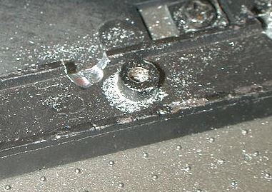 (editor's note) When you do the grinding, shield the engine
assembly and the trucks with paper towels so that the metal
shavings do not stick to the oil that's probably all over the
exposed moving parts. When this picture was taken, I had vacuumed
up all the big pieces. It took wiping with a cotton swap to pick up
all the little stuff.
(editor's note) When you do the grinding, shield the engine
assembly and the trucks with paper towels so that the metal
shavings do not stick to the oil that's probably all over the
exposed moving parts. When this picture was taken, I had vacuumed
up all the big pieces. It took wiping with a cotton swap to pick up
all the little stuff.
There are many production variations of clearance between the arm on the rear of the reverse shaft (that you pulled the pin from) and the cab support right next to it. On my unit (early), to clear the support, I only had to bend the arm slightly forward. Worse case on some is the arm must be removed from the shaft or the cab support must be trimmed or removed. Make sure the links move freely in and out with no interference to the support.
Once this is done, finish the installation by twisting the dogs of the lug 90 degrees, reinstall the firebox cover.
You may not get smooth engagement at first, and you may need to oil frequently for the first week or so, but the links should shift fully in about one actual foot of track movement. Visitors may not notice this at first, but you can point it out to them, and YOU know it works!
Dave Goodson-NWRCS
The Old Curmudgeon
Most Shays tend to make an annoying tap-tap sound as the engine runs. After a year and a half of listening to it and making marginally effective stabs at making it go away, I've at least figured out exactly what is happening.
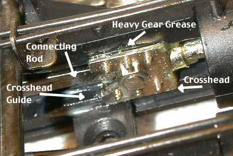 The tapping is caused by an
interaction between the connecting rod, the crosshead and the sound
switch. When the piston rod pushes all the way up into a cylinder,
it contacts a leaf switch which is used to trigger a chuff from a
sound system. The pressure caused by the switch is slight, but it
is enough to cause the crosshead to cock slightly in the crosshead
guides. The direction that it cocks is determined by the angle of
the connecting rod working against the crankpin. As the connecting
rod moves over top dead center, its angle changes to the other
direction, and the crosshead snaps to the other crosshead guide
causing an audible tap.
The tapping is caused by an
interaction between the connecting rod, the crosshead and the sound
switch. When the piston rod pushes all the way up into a cylinder,
it contacts a leaf switch which is used to trigger a chuff from a
sound system. The pressure caused by the switch is slight, but it
is enough to cause the crosshead to cock slightly in the crosshead
guides. The direction that it cocks is determined by the angle of
the connecting rod working against the crankpin. As the connecting
rod moves over top dead center, its angle changes to the other
direction, and the crosshead snaps to the other crosshead guide
causing an audible tap.
I found that covering the crosshead guide with heavy gear grease damps the movement of the crosshead and tends to prevent the tap sound. Since it is very difficult to get to both crosshead guides even with a grease bearing toothpick, this operation is more easily performed with the engine assembly removed from the locomotive. You can follow the directions in the section above for removing the engine. You also need to unsolder the two wires going to the sound switch and solder them back on when you reinstall the engine assembly.
A permanent fix for this problem is to entirely remove the sound switch assembly. The whole contact assembly comes off the back of the engine assembly with three screws. Your sound system will then need to use another method to set the chuff rate, perhaps by voltage controlled chuffing or with another sound contact switch installed somewhere else.
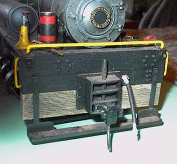
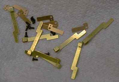
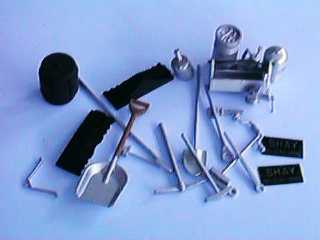 The Shay comes with an assortment of
tools and accessories that can be hung or placed anywhere a real
tool might be found.
The Shay comes with an assortment of
tools and accessories that can be hung or placed anywhere a real
tool might be found.
After some considerable discussion on the LSOL Workshop Rick Henderson offers that the item in the lower left is a clamp to hold down the two re-railers. It seems plausible.
 Silver Ridge Mining Co. in Mesa AZ
(602-854-0418) makes a cast resin oil bunker ($23 +$2 shipping) for
the Shay for those of you who would like to convert your Shay to
oil. This casting is highly detailed and takes about 2 minutes flat
to install. Coal and wood burners produced a lot of cinders and
tended to start fires. This was a special problem for loggers. Many
logging Shays were converted to burn oil to reduce the burning
cinder problem. In many locations, oil was easier to obtain than
coal and didn't require much in the way of fueling equipment except
a tank truck and a pump.
Silver Ridge Mining Co. in Mesa AZ
(602-854-0418) makes a cast resin oil bunker ($23 +$2 shipping) for
the Shay for those of you who would like to convert your Shay to
oil. This casting is highly detailed and takes about 2 minutes flat
to install. Coal and wood burners produced a lot of cinders and
tended to start fires. This was a special problem for loggers. Many
logging Shays were converted to burn oil to reduce the burning
cinder problem. In many locations, oil was easier to obtain than
coal and didn't require much in the way of fueling equipment except
a tank truck and a pump.
Daniel Daugherty writes: You should mention the Hillside Railways Flickering Firebox kit for the B-Shay. $99.00 replaces the complete wiring loom, all lights,(to LGB 5v), gives constant lighting, better and brighter firebox lights, and has provisions for either an 18v or 5v smoke unit. It's a wonderful upgrade, and well worth the price. If your interested, contact Dennis @ Hillside Railways, 25746 Po Ave., Mission Viejo, CA 92691. Phone (949) 586-6292.
[ Top ]Some Shays seem to be experiencing rapid failure of the bushings that hold the wheels in place. The exact cause of the failures is up for conjecture, however a bad batch of plastic is probably part of the problem. In any event, the symptom is unmistakable, the wheels almost fall off.
My two Shays came over on the first boatload and both have many hours on them Neither shows any sign of trouble. A friend of mine put his on the track and ran it for less than an hour before ALL of the bushings began to fail or completely crumbled.
An early symptom of the failure is a wobble or looseness in a wheel. If a wheel can be turned, even a little, with respect to the other wheel on the axle, there is a problem. This will get progressively worse until the wheel comes completely loose.
Since I've never had this problem, I don't have a fix for it. However, Dave Goodson had developed a Shay Fix it Kit which is now available through Bachmann. The kit contains 8 nylon washers, 12 steel washers, 4 larger steel washers and 8 longer screws plus instructions. The kit does NOT contain replacement bushings. If you need these, make sure that you ask Bachmann for them when you order the Fix it Kit.
[ Top ]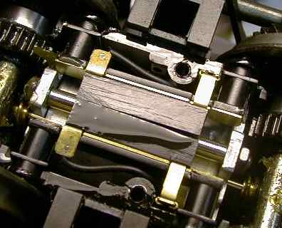 The Shay uses spring loaded
ball bearings to pick up power from the wheel backs. They work well
enough most of the time, but if the current load gets too high,
they tend to melt down because the contacts are enclosed in plastic
holders. This appears to be a special problem when the Phoenix Big
Boost is used on the Shay. At low voltages, the Big Boost draws a
lot of current trying to keep the sound system running at full
power and several Shay owners have experienced melt down.
The Shay uses spring loaded
ball bearings to pick up power from the wheel backs. They work well
enough most of the time, but if the current load gets too high,
they tend to melt down because the contacts are enclosed in plastic
holders. This appears to be a special problem when the Phoenix Big
Boost is used on the Shay. At low voltages, the Big Boost draws a
lot of current trying to keep the sound system running at full
power and several Shay owners have experienced melt down.
 Hillside Railways, (949) 586-6292, has released an upgrade kit for
the Shay contacts. The upgrade still uses ball bearings for
contacts, but the housings are made of brass and can take the heat
of high contact current. The kit provides new contact holders but
reuses the motor contact tabs and the jumper tabs to the truck
contacts. Hillside provides an extra set of ball bearings in case
you lose some. The instruction sheet is clear and complete. The kit
can be installed on both trucks in about 20 minutes with little
difficulty.
Hillside Railways, (949) 586-6292, has released an upgrade kit for
the Shay contacts. The upgrade still uses ball bearings for
contacts, but the housings are made of brass and can take the heat
of high contact current. The kit provides new contact holders but
reuses the motor contact tabs and the jumper tabs to the truck
contacts. Hillside provides an extra set of ball bearings in case
you lose some. The instruction sheet is clear and complete. The kit
can be installed on both trucks in about 20 minutes with little
difficulty.
After I had done the front truck, I checked it out with a Kadee contact brush. As I was testing for power pickup, I noticed that the motors seemed to run faster when the front wheels were used for pickup. I measured my power supply voltage when the motors just started to move. With the power applied to the front truck, the motors would just start to turn at 1.7 volts. When applying power to the rear unconverted truck, it took 3.9 volts to start the motors and the motor movement was much less steady. Upon conversion of the rear truck, the motors would start at 1.7 to 1.8 volts when power was applied to either truck.
The implication of the lower starting voltage is that the Hillside contacts have less resistance than the original contacts and should heat less. Because they are brass, they should be able to handle whatever heat is left even better.
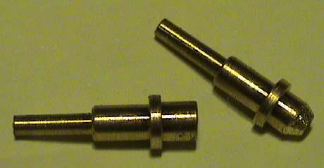
If you want to convert your Shay to battery power, it is a good idea to disable the power pickups so that the loco doesn't backfeed power to the track. This can be done easily.
The original Shay power
pickups are ball bearings held in plastic holders. The ball
bearings are pressed against the wheel back by a small brass piston
and a spring. The easiest way to disable them is to remove the
springs from the backside of the holders while leaving the ball
bearings and contact pistons in place. They will flop around inside
the pickup housing, but without the spring, neither of them are
long enough to reach the wheel and the backside contact strap at
the same time.
There is a straight brass strap that goes behind the two power pickups on each side. This connects the pickups together. Also contacting this strap is a brass jumper that connects to another brass strap that goes to the top of the truck. There is also a brass tab that the motor wire is soldered to. Pull the motor tab and the jumper out of the truck. Carefully pull out the strap that goes behind the pickups. The springs will come partially out. Use tweezers to remove the springs and then put the three brass parts back in place. Then do the other side and then the other truck. Save the springs in case you want to convert the loco back. You can now feed battery power down to the motor through the original wires.
If you want to convert the Shay to a track powered command control system like DCC, you will have to do some new wiring. Track powered command control systems require that the motor and power pickup wiring is isolated from one another. Bachmann claimed at one time that they would design their locos with separate power and motor wiring, but it hasn't happened yet.
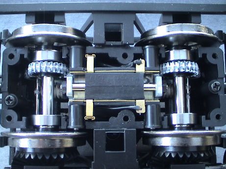
 The Shay
uses a spring finger contact system to connect the truck to the
loco frame. The power pickups and motor connections are brought to
the top of the truck on brass straps that hook over the top of the
truck. This system works quite well and has low voltage drop. It
also allows the truck to be easily removed from the loco for
service if needed. I wanted to retain this contact system for the
motor wires as well as the power pickup wires.
The Shay
uses a spring finger contact system to connect the truck to the
loco frame. The power pickups and motor connections are brought to
the top of the truck on brass straps that hook over the top of the
truck. This system works quite well and has low voltage drop. It
also allows the truck to be easily removed from the loco for
service if needed. I wanted to retain this contact system for the
motor wires as well as the power pickup wires.
 The contacts are pressed against spring fingers on the bottom of
the truck bolster to make the connection to the engine body. From
this photo, and the previous one, it can be seen that there are
features available to attach a second set of contacts that could be
used to feed motor power back down to the truck from the engine
body.
The contacts are pressed against spring fingers on the bottom of
the truck bolster to make the connection to the engine body. From
this photo, and the previous one, it can be seen that there are
features available to attach a second set of contacts that could be
used to feed motor power back down to the truck from the engine
body.
 I
could have made the parts to add the extra contacts, but I elected
to buy them from Bachmann instead. $7.20 bought me enough parts to
do two complete locos. The bolster contacts are all the same, four
are required for one loco. The truck contact straps come in a left
hand and right hand version, two of each are needed. I also got the
little screws to hold on the bolster contacts, four are needed for
one loco.
I
could have made the parts to add the extra contacts, but I elected
to buy them from Bachmann instead. $7.20 bought me enough parts to
do two complete locos. The bolster contacts are all the same, four
are required for one loco. The truck contact straps come in a left
hand and right hand version, two of each are needed. I also got the
little screws to hold on the bolster contacts, four are needed for
one loco.
 The contact straps fit just
a little too close the Hillside Railways contact kit that had been
previously installed in this Shay, so I trimmed them just a little
to make more clearance.
The contact straps fit just
a little too close the Hillside Railways contact kit that had been
previously installed in this Shay, so I trimmed them just a little
to make more clearance.
 Once the
contact is inserted in the truck, just unsolder the motor wire from
its tab and resolder it back to the end of the new strap.
Once the
contact is inserted in the truck, just unsolder the motor wire from
its tab and resolder it back to the end of the new strap.
 The
original contact is held in place by the brass jumper strap at the
bottom. Since there is nothing to hold the new contact in place, I
attached it at the top with a small drop of Zap-CA CA. It would be
really unfortunate if the strap should move and touch the adjacent
track power contact at the bottom. This would almost certainly
cause the untimely demise of a DCC decoder.
The
original contact is held in place by the brass jumper strap at the
bottom. Since there is nothing to hold the new contact in place, I
attached it at the top with a small drop of Zap-CA CA. It would be
really unfortunate if the strap should move and touch the adjacent
track power contact at the bottom. This would almost certainly
cause the untimely demise of a DCC decoder.
 The new truck contacts
connect to new bolster contacts which are simply screwed in place
in the provided holes in the bolster. New motor wires are run to
the new contacts and soldered.
The new truck contacts
connect to new bolster contacts which are simply screwed in place
in the provided holes in the bolster. New motor wires are run to
the new contacts and soldered.
To route the new wire to the front truck, remove the smokebox front and then remove the smoke unit. Remove the ashpan cover and then push the new wire pair down the hole in the top of the firebox along with the rest of the wires. A little fishing around will cause the new wire to head to the front. Insert the new wire pair into the truck bolster with the existing pair.
Depending on where you mount your DCC decoder will determine where the other end of the wire goes. I ran it back through the wire tunnel to the tender where a DCC decoder will eventually reside. The rear motor wires are simply run up into the tender.
I finally broke down and installed more computer power in a model Shay than ever existed in a real Shay. I installed DCC and digital sound. The systems I selected are the best currently available for the money, a Lenz LE230 DCC decoder and a Soundtraxx Sierra.
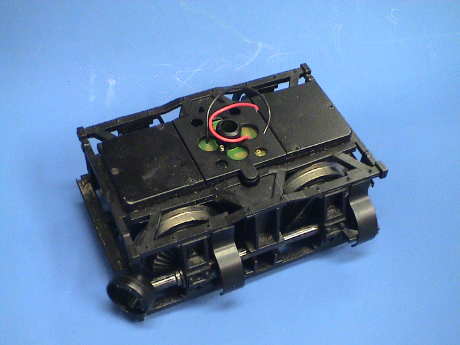
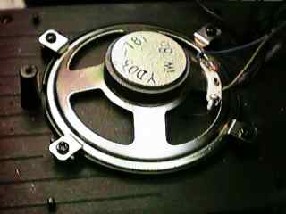 This Shay had an analog
sound system in it. I had hacked an old sound board out of an RC
Big Hauler and hung it in the Shay. I also took the speaker, which
was a surprisingly good one, from the RC Big Hauler. I determined
that this speaker sounded just as good as the best small speaker
that I had so I elected to use it.
This Shay had an analog
sound system in it. I had hacked an old sound board out of an RC
Big Hauler and hung it in the Shay. I also took the speaker, which
was a surprisingly good one, from the RC Big Hauler. I determined
that this speaker sounded just as good as the best small speaker
that I had so I elected to use it.
 Mounting the sound board and the decoder to the tender shell would
have been both easy and difficult. The mounting part would be easy,
the wiring would have been a bear. Since only two wires actually
need to go to the shell (the rear headlight) attaching the boards
to the shell would have resulted in a large bundle of wires going
from the frame to the tender shell, an undesirable condition. I did
the Climax that way and it was a pain. Not only is it difficult to
wire and maintain, the continual flexing of wires as the shell was
removed and installed will eventually result in broken wires and
possible electrical damage if the wrong wire touches the
uninsulated sound and DCC boards.
Mounting the sound board and the decoder to the tender shell would
have been both easy and difficult. The mounting part would be easy,
the wiring would have been a bear. Since only two wires actually
need to go to the shell (the rear headlight) attaching the boards
to the shell would have resulted in a large bundle of wires going
from the frame to the tender shell, an undesirable condition. I did
the Climax that way and it was a pain. Not only is it difficult to
wire and maintain, the continual flexing of wires as the shell was
removed and installed will eventually result in broken wires and
possible electrical damage if the wrong wire touches the
uninsulated sound and DCC boards.
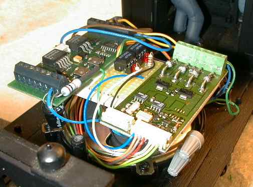
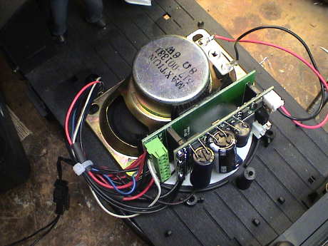
Instead, I elected to mount the boards on the back of the speaker. I attached a small piece of 0.062 styrene with foam tape to the speaker magnet and then attached the boards to the styrene with more foam tape. The boards were just short enough to clear the lead weight at the back and the SilverRidge Mining Co. oil bunker at the front. This way, all but two wires are permanently installed. The headlight wires are connected with a two pin connector so that I can remove the shell entirely for testing and maintenance. The small board in the middle holds two optoisolators used to transmit whistle and coupler clank sound triggers to the sound system from the DCC decoder. Later two more optoisolators were added to isolate the decoder motor connections from the sound system as well.
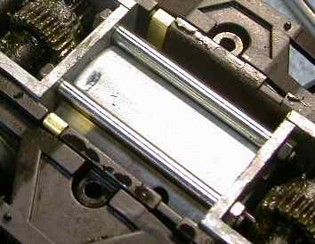
 There was one complication
however, the whole assembly was too tall to fit inside the stock
tender shell. I can't remember how the stock coal load fitted, but
with the oil bunker on top of the tender, the plastic ridges that
extended down into the tender were unnecessary so I hacked them
off. This allowed the boards to fit.
There was one complication
however, the whole assembly was too tall to fit inside the stock
tender shell. I can't remember how the stock coal load fitted, but
with the oil bunker on top of the tender, the plastic ridges that
extended down into the tender were unnecessary so I hacked them
off. This allowed the boards to fit.
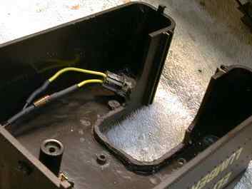
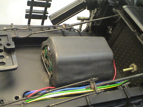
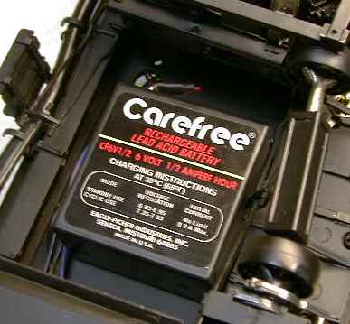 A standard hack
for Shay sound installations is to mount the battery under the
frame just in front of the rear truck. The battery won't fit well
unless the wiring tunnel is removed which is no problem as the
wiring can't be seen anyway. The battery can be seen, but since it
is black and nondescript, it isn't visually obtrusive. The bright
red and white lettering faces downward so it cannot be seen.
A standard hack
for Shay sound installations is to mount the battery under the
frame just in front of the rear truck. The battery won't fit well
unless the wiring tunnel is removed which is no problem as the
wiring can't be seen anyway. The battery can be seen, but since it
is black and nondescript, it isn't visually obtrusive. The bright
red and white lettering faces downward so it cannot be seen.
I wired the system two different ways. The first way was a little simpler, but it couldn't keep the battery charged. The second way keeps the battery charged but is slightly more complicated.
Running without any charge source at all, the Sierra sound system will discharge its battery in about 45 minutes. When the system is wired with connections 7 and 8 connected to an average motor, the battery will get some charge and the system will run for maybe 2 hours. Running from a DCC decoder which outputs PWM and charging from the motor as shown in the first schematic, the battery will last maybe 4 hours or so.
However, even this didn't satisfy me so I rearranged the wiring again so that the battery is continuously charged from the 9 volt regulator on the Shay flicker board and the battery will NEVER run down when run from DCC on the track. With Aristo PWC on the track the battery will get net charge as long as the engine is moving, even very slowly. With DCC on the track and the battery completely flattened by running with the flicker board turned off, the system will start to run again immediately when the flicker board is activated and it begins to charge the battery. With DCC, the battery will be trickle charged as long as the engine sits on DCC energized track, running or not.
 The first method that I chose is very simple wiring scheme.
Soundtraxx recommends a different approach in their Technical Note
#7. They recommend not using the battery and running the sound
system from DCC track power. Since I wanted this engine to run on
analog track power as well as DCC (my DCC conversion is going
slowly and analog conversion is important to me for the interim) I
elected to retain the battery and allow it to charge from the PWM
pulses generated by the DCC decoder. The disadvantage of this
approach is that optoisolators are necessary to isolate the DCC
decoder function outputs from the sound triggers. Installing
optoisolators is no big deal, see my Sound Tips page for
details.
The first method that I chose is very simple wiring scheme.
Soundtraxx recommends a different approach in their Technical Note
#7. They recommend not using the battery and running the sound
system from DCC track power. Since I wanted this engine to run on
analog track power as well as DCC (my DCC conversion is going
slowly and analog conversion is important to me for the interim) I
elected to retain the battery and allow it to charge from the PWM
pulses generated by the DCC decoder. The disadvantage of this
approach is that optoisolators are necessary to isolate the DCC
decoder function outputs from the sound triggers. Installing
optoisolators is no big deal, see my Sound Tips page for
details.
Even though the Sierra has its own flicker circuits that could drive firebox lights, the Sierra lighting circuits draws power from its battery so I elected to minimize the load on the Sierra's battery by retaining the Bachmann flicker board. I did hook the flicker board to track power through a switch so that I could disconnect it from the track during decoder programming.
I also replaced the stock Bachmann smoke element with an LGB 24 volt element. At my track voltage of 22 volts, the LGB element really cooked, quite literally. It smoked much too strongly. Adding a resistor in series with the smoke element decreased its dissipation to about 1.5 watts. This is the same dissipation as the 5 volt elements which smoke fine and also seem to have a very long life and are tolerant to running dry.
The Sierra is hooked up only to the motor leads of the Lenz DCC decoder and through optoisolators for function control. This is the safest approach and the least likely to cause any damage to the DCC decoder or to the Sierra. The Sierra then senses motor voltage and can operate its voltage controlled effects based on engine speed. However, there was a problem. The Sierra was being fooled by something coming out of the decoder. It would only play its starting or stopping effects when the DCC power was applied or removed from the track. Even though the chuff (wired to the Bachmann sound switch contacts) and bell worked fine, the automatic whistle signals did not.
I guessed that there had to be switching transients leaking out the decoder that were confusing the Sierra so I added a 0.1 uF capacitor across the Sierra's input (the decoder's output) and the effect changed. The forward startup (two toots) and the stopping sounds (hiss and one toot) worked OK, but the reverse signal played the forward signal instead. I consulted with Soundtraxx and they recommended adjusting the auto-exhaust startup voltage. While this did have some effect, it didn't fix the problem.
I found by experiment that a more substantial RC filter was necessary to clean off the switching transients that were confusing the Sierra. I settled on a 10uF NON POLARIZED capacitor and a 22 ohm 5 watt resistor as the filter. Smaller capacitors (1 uF) did not have sufficient filtering effect, and smaller series resistors allowed too much ripple current to flow to the capacitor which beat up on both on the resistor and the decoder.
With a fully charged battery, the Sierra draws about 60 mA at idle (above 9 volts which is necessary to wake up the unit), about 200 mA fast chuffing and up to 500 mA fast chuffing with the whistle blowing so there can be substantial dissipation in the resistor. Also, when charging the battery, the unit requires 10 volts and draws an input current of about 250 mA without the chuffs or whistle. At a 400 mA typical load (200 mA to run the system while chuffing and 200 mA to charge the battery), the resistor drops about 9 volts but still allows the Sierra to try to charge the battery from the DCC decoder motor pulses. It is important to charge the battery at the maximum rate possible as it will charge only when the motor pulses are actually on.
When the whistle is blowing, the resistor can get slightly overloaded but since the whistle doesn't last too long, this isn't a problem. The resistor also removes significant dissipation from the internal regulator in the Sierra which would get rather hot otherwise. Even with this filter, some adjustment of the auto-exhaust start voltage may be required.
There is dark side to using an external resistor. When the whistle blows, the voltage drop in the resistor increases and the voltage delivered to the Sierra decreases. When the whistle signal finishes, the current goes down, the voltage applied to the Sierra increases and the Sierra thinks that it got another whistle trigger and blows the whistle again. The thing turns into an oscillator, continually retriggering itself. You will need to set the whistle sensitivity and filter rate such that the automatic grade crossing whistle NEVER blows or it will NEVER STOP blowing. Try a sensitivity value of 10 and a filter rate of 1. That should kill it for good. If you really want a grade crossing signal, wire a decoder function to trigger the whistle through an optoisolator so that it will blow ONLY when you want it to. See my Sound Tips page for details on using an optoisolator.
Note that if you do trigger the whistle with a decoder function, you will get only the grade crossing signal unless you program the remotely controlled whistle mode where you have to blow all the whistles yourself, the automatic whistle signals are disabled. The Westside Shay version of the Sierra does not have particularly good remotely controlled short whistle signal control, actually it is pretty poor. You'll be more pleased with the automatic whistle signals.
This method worked pretty well, but after extended low speed running, 4 hours or more, the battery would still become discharged and the sound system would freak out. The symptom of a discharged battery is continual popping and whistle blowing as the system shuts down and resets. This doesn't hurt the system, but it sounds terrible.
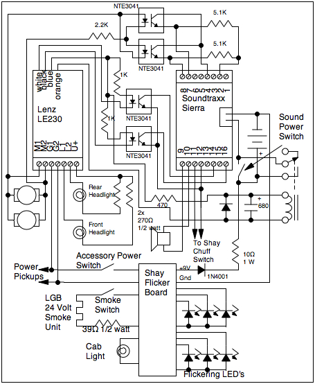 To fix the battery charging problem, I elected to rearrange the
wiring. Instead of trying to charge the battery from the motor
circuits through the Sierra, the battery is charged by an on board
charger derived from the 9 volt regulator on the Shay flicker
board. A diode and a resistor are added in series between the
regulator and the battery. The diode prevents the battery from
discharging back into the regulator when there is no track power.
The resistor limits the charging current so that the battery will
not be cooked and the regulator will not be overloaded. A 10 ohm
resistor allows the system to run from the regulator even if the
battery is flat. After the sound system takes it share, there is
still enough current left over to charge the battery at a low rate.
If the sound system is turned off with the battery flat, the charge
current is limited to about 200 mA which is the rating of the
battery. When the battery becomes charged and its voltage
increases, the charge current decreases to a 25 mA trickle which
the battery can handle continuously. Note that the battery is
always hooked up the charger circuit.
To fix the battery charging problem, I elected to rearrange the
wiring. Instead of trying to charge the battery from the motor
circuits through the Sierra, the battery is charged by an on board
charger derived from the 9 volt regulator on the Shay flicker
board. A diode and a resistor are added in series between the
regulator and the battery. The diode prevents the battery from
discharging back into the regulator when there is no track power.
The resistor limits the charging current so that the battery will
not be cooked and the regulator will not be overloaded. A 10 ohm
resistor allows the system to run from the regulator even if the
battery is flat. After the sound system takes it share, there is
still enough current left over to charge the battery at a low rate.
If the sound system is turned off with the battery flat, the charge
current is limited to about 200 mA which is the rating of the
battery. When the battery becomes charged and its voltage
increases, the charge current decreases to a 25 mA trickle which
the battery can handle continuously. Note that the battery is
always hooked up the charger circuit.
The connections on the flicker board to pick off the +9 volts and ground are not marked. +9 volts is most easily found on the center pin of the regulator. Ground is found on one lead of R2, a 1.5K resistor. On my unit, R2 was stuffed on the board such that the lead on top was the ground lead. Its the one nearest the center of the board. The resistor on your unit might be stuffed differently so you need to check to make sure that you are really using the ground lead.
Soundtraxx provides a circuit in their Technical Note #7 which shows that the Sierra can be connected to the track though a power supply circuit and still be connected to a motor on a DCC decoder. Maybe this works, but I have never trusted these "virtual ground" type connections. I elected to optoisolate the motor connections to the Sierra as shown in Technical Note #6 when the Sierra is connected to an Aristo 5490 mini-receiver. This approach requires two more optoisolators and three resistors, but it works very well and completely isolates the sound system from the DCC decoder. Optoisolators are cheap and reliable.
Depending on the polarity of the motor drive signal, one of the two optoisolators is activated and either pin 7 or pin 8 of the Sierra is pulled up. The Sierra can use this kind of signal to determine the motor voltage (based on pulse width) and polarity to operate its voltage controlled effects. This circuit gave me no troubles like I had with the direct connection and I recommend using it even if it doesn't seem to be absolutely necessary. It is cleaner and safer.
Later, a relay was added connected to F6 of the LE230 to allow the sound to be turned on remotely. It will also turn off automatically when DCC power is lost for more than a half a second or so. This prevents me from leaving the sound system on and flattening the battery when I put the loco away. In the Shay and Climax I used a different kind of relay because I ran out of the ones that I used for all the other Sierra installations. This relay required a larger series resistor and a much larger hold on capacitor.
 Eventually, the Sierra battery
gave up as they are likely to do. After 5 years of non-operation,
the battery was dead so it was replaced, like all the others, with
a 5 cell NiMH pack. The symptom of a dead battery in this
configuration is a series of pops. With the replaced battery, the
system came back to life after the new battery had charged for only
a few seconds.
Eventually, the Sierra battery
gave up as they are likely to do. After 5 years of non-operation,
the battery was dead so it was replaced, like all the others, with
a 5 cell NiMH pack. The symptom of a dead battery in this
configuration is a series of pops. With the replaced battery, the
system came back to life after the new battery had charged for only
a few seconds.
It's October 2008 and it has been 10 years since I did a DCC install in a Shay. I finally got around to installing DCC in the other one. I bought two of the first run Bachmann Shays. One stayed at the GIRR and was converted to DCC long ago. The other went to the GIRR Mountain Division, which was until a few days ago, analog track power. This time, I used a combination DCC decoder and sound system, the QSI Magnum. This is really a plug and play sound decoder configured to plug into an AristoCraft loco, but it came with an adapter board that has screw terminals. This is clearly the largest, volume wise, decoder that I have come across and it's size caused some problems. However, in the end it worked well.
Since I discussed the previous DCC installation in the Shay in detail above, I'll only comment on the things that were different in this installation. I used this page for instructions because I didn't actually remember much of what I did before.
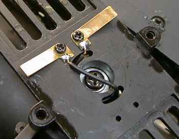
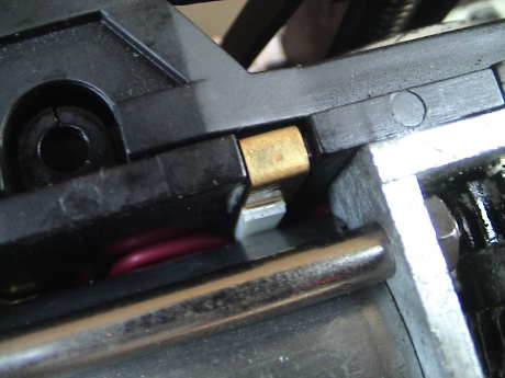
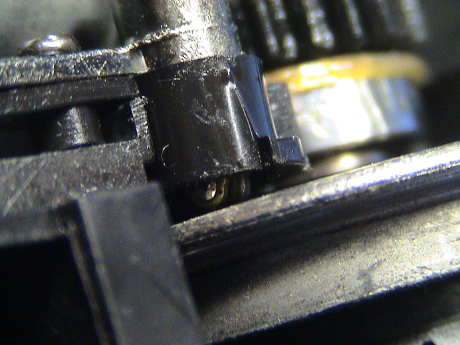
 The first task in any DCC installation is to isolate the motor. I
actually was able to find the rest of the contact parts that I
purchased from Bachmann so I used them as before EXCEPT I insulated
the motor contacts better. This photo shows a piece of 1/4" shrink
tube insulating the new motor contact. It is also glued to the
brick housing with Zap-A-Gap, but even if the glue joint breaks,
the contact cannot touch the adjacent piece of the power pickup
assembly. This loco still has the Hillside kit and it is working
fine.
The first task in any DCC installation is to isolate the motor. I
actually was able to find the rest of the contact parts that I
purchased from Bachmann so I used them as before EXCEPT I insulated
the motor contacts better. This photo shows a piece of 1/4" shrink
tube insulating the new motor contact. It is also glued to the
brick housing with Zap-A-Gap, but even if the glue joint breaks,
the contact cannot touch the adjacent piece of the power pickup
assembly. This loco still has the Hillside kit and it is working
fine.
 I also placed a piece of 0.030" styrene between the motor housing
and the motor contact. This is to prevent the possibility of the
motor contact touching the metal motor housing. This wouldn't
actually be a problem, but if the one on the other side did too, it
would short the decoder.
I also placed a piece of 0.030" styrene between the motor housing
and the motor contact. This is to prevent the possibility of the
motor contact touching the metal motor housing. This wouldn't
actually be a problem, but if the one on the other side did too, it
would short the decoder.
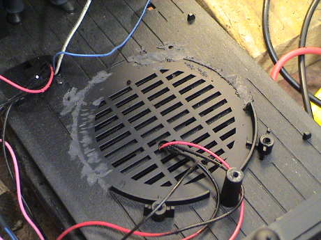 The
major difference in the installation is that I didn't use a round
3" speaker. The one that was in there wasn't a very good one. This
Shay had a Bachmann analog board that I recovered from a defunct RC
Big Hauler. The analog board doesn't have much bass sound at all
and it worked fine with a low performance speaker. I have a much
better 3" speaker that fits, but the QSI would not fit in the
tender with either speaker. The centrally mounted speaker was
consuming too much of the sweet spot in the middle of the tender.
The QSI decoder is much too tall to mount on top of the speaker as
the LE230 did.
The
major difference in the installation is that I didn't use a round
3" speaker. The one that was in there wasn't a very good one. This
Shay had a Bachmann analog board that I recovered from a defunct RC
Big Hauler. The analog board doesn't have much bass sound at all
and it worked fine with a low performance speaker. I have a much
better 3" speaker that fits, but the QSI would not fit in the
tender with either speaker. The centrally mounted speaker was
consuming too much of the sweet spot in the middle of the tender.
The QSI decoder is much too tall to mount on top of the speaker as
the LE230 did.
Instead, I used an oval speaker as I usually use with sound systems. This is actually a much larger speaker than the round ones, but it's shape allows it to be offset to the front leaving room for the decoder behind it. This meant that I had to grind off half of the mounting features for the round speaker. I also had to grind off the underside of the tender as in the previous installation. I also had to grind a relief on the inside of the aftermarket oil tank as it also interfered with the speaker.
The unused speaker slots were covered with a piece of sheet styrene held down with hot glue. The speaker itself is also mounted with hot glue.
 This is the completed installation. The QSI decoder board is
mounted to the speaker with adhesive backed Velcro. I didn't need
any funny interface circuits, all of the wiring is connected
directly to the decoder screw terminals except for the speaker
which plugs into the decoder board. As in the previous
installation, the motor wires were both routed to the tender. In
this case I abandoned the chuff wires as the QSI autochuffs very
well, it does not need a chuff trigger. The rear headlight wires
were disconnected from the flicker board and pulled back into the
tender. The front headlight wires were disconnected from the
flicker board and extended back to the tender. The power from one
side of the loco was disconnected from the flicker board and run
through a switch (installed in the rear wall of the firebox) to
allow the flicker board to be taken off-line during decoder service
mode programming. However, most of the programming for the decoder
is done in OPS mode and the decoder provides voice feedback of what
you do in OPS mode so that this switch will be rarely used. The
smoke unit and cab light still run directly from the flicker
board.
This is the completed installation. The QSI decoder board is
mounted to the speaker with adhesive backed Velcro. I didn't need
any funny interface circuits, all of the wiring is connected
directly to the decoder screw terminals except for the speaker
which plugs into the decoder board. As in the previous
installation, the motor wires were both routed to the tender. In
this case I abandoned the chuff wires as the QSI autochuffs very
well, it does not need a chuff trigger. The rear headlight wires
were disconnected from the flicker board and pulled back into the
tender. The front headlight wires were disconnected from the
flicker board and extended back to the tender. The power from one
side of the loco was disconnected from the flicker board and run
through a switch (installed in the rear wall of the firebox) to
allow the flicker board to be taken off-line during decoder service
mode programming. However, most of the programming for the decoder
is done in OPS mode and the decoder provides voice feedback of what
you do in OPS mode so that this switch will be rarely used. The
smoke unit and cab light still run directly from the flicker
board.
The QSI decoder has only two function outputs, these are preconfigured for the headlights so I wired the incandescent headlamps directly to the QSI. This was a little confusing because the stenciling on the board itself and the instructions were in conflict concerning the identification of the forward and rearward headlights. I went with the board stencil which turned out to be correct. I also forgot that the headlight bulbs are 9 volt bulbs. The decoder was providing about 14 volts so that they were REALLY bright. I had to install a 100 ohm 1/4 watt resistor in series with each one to bring them back to 9V where they draw 50 mA each.
When I changed out the bricks on this loco a couple of years later due to split gears, I noticed that the rear headlight was not working. When I cracked open the loco I found that the 100 ohm voltage dropping resistor had burned up. After a little trouble shooting, it turns out that the rear bulb was loose in the headlight assembly and the leads were intermittently shorting to the metalization on the inside of the reflector. This is what burned up the resistor and also why these resistors are a good deal. Without a current limiting resistor, the function output of the decoder would have failed. My track voltage on my test track is higher than what the GIRR Mtn Div was, 18 volts vs 16 volts. Since I did this install, I had bumped the track voltage on the GIRR Mtn Div so that the decoder was providing more output voltage, more like 16 volts so I increased the resistors to 150 ohms. The lights were too bright with the 100 ohm resistors and were overstressed. The lights are not quite as bright now, but at least the bulbs will last longer.
The QSI decoder deserves much more discussion, but I'll be doing that in my QSI Tips page sometime later when I've come to know this puppy a little better.
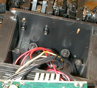
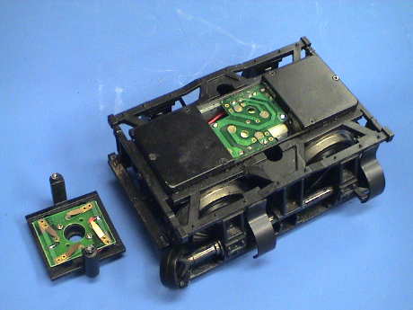
I finally had a wheel loosen up on one of the Shays. To tighten it requires that the brake beam and bearing assemblies be removed. This is not difficult, but a lot of screws have to be removed to tighten one lousy wheel mounting screw.
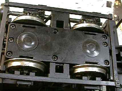 First, the
truck needs to be removed from the engine. On this older truck, the
two long screws on the bottom cover (the ones in the middle at each
end) need to be removed. On newer trucks, these are under the
bottom cover. Then two short screws need to be removed from way
down in those square black holes at both sides near the center.
Once these screws are removed the truck can simply be lifted off
the engine.
First, the
truck needs to be removed from the engine. On this older truck, the
two long screws on the bottom cover (the ones in the middle at each
end) need to be removed. On newer trucks, these are under the
bottom cover. Then two short screws need to be removed from way
down in those square black holes at both sides near the center.
Once these screws are removed the truck can simply be lifted off
the engine.
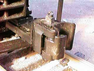
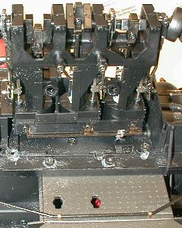
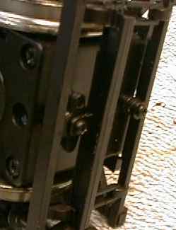
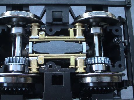
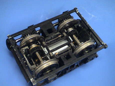
 The entire
brake beam and bearing assembly must be removed in one piece. It
slides off (with some difficulty) upward. To remove it, the drive
shaft has to come off. There are four screws that hold on the
shaft. When the screws are removed, the entire shaft assembly will
come off. The gear covers will simply pull off. There is also a
small screw on each side at the lower center of the sideframe which
must be removed. One of them can barely be seen in the upper right
of this photo.
The entire
brake beam and bearing assembly must be removed in one piece. It
slides off (with some difficulty) upward. To remove it, the drive
shaft has to come off. There are four screws that hold on the
shaft. When the screws are removed, the entire shaft assembly will
come off. The gear covers will simply pull off. There is also a
small screw on each side at the lower center of the sideframe which
must be removed. One of them can barely be seen in the upper right
of this photo.
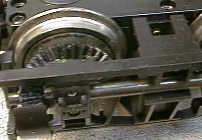
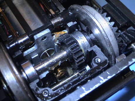
 There are four
more screws, two on each end of the brick that must be removed. To
get to one of them on the end with the coupler mount, the mount
must be removed also. The brake beams are still held in place by
four pins, two at each end of the truck. The ends of the brake
beams can be gently pried away from the brick to release the pins.
Then the whole brake beam and bearing assembly can be worked upward
and off of the truck. This exposes the wheel mounting screws that
get loose and infamous bushings that crumble.
There are four
more screws, two on each end of the brick that must be removed. To
get to one of them on the end with the coupler mount, the mount
must be removed also. The brake beams are still held in place by
four pins, two at each end of the truck. The ends of the brake
beams can be gently pried away from the brick to release the pins.
Then the whole brake beam and bearing assembly can be worked upward
and off of the truck. This exposes the wheel mounting screws that
get loose and infamous bushings that crumble.
At this point, the wheels can be removed and the brushes either serviced or removed during a battery R/C conversion. You might also want to check the nuts that hold the gear plates against the motor. They tend to get loose.
Reassembly is done in the reverse order.
My Shay basically sat on a shelf for about 3 years at one point while I was attending to other matters, such as an intensive work schedule. By the time I got back to it, it didn't run. 3 of the axles would free rotate. This was due to failure of the nylon drive gears on the axles. They had split from age. Since there were other problems with cracked plastic on this set, I contacted Bachmann and got them replaced. It cost $50, but I got two entirely new trucks and top covers.
Both trucks ran when placed on the track, but all was not right. Somewhere along the line, either I or Bachmann had reversed the position of the power pickups. They used to be in the "inboard" position, nearest the center of the loco. On the new ones, they are in the outboard position. This means that when I remove the old top covers (due to cracks) to replace them, I have to reverse the positions of the contacts mounted on them as well.
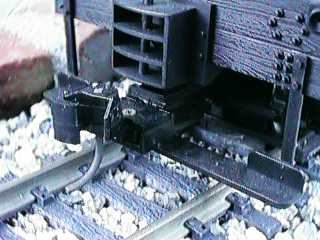
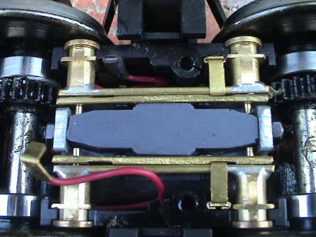
 This
is the stock front truck. The front of the loco would be to the
left, placing the power pickup points to the outboard position.
Further, the power pickups themselves are still the plastic sleeved
ones. They appear to be identical to the original design which
tended to fail at high loads.
This
is the stock front truck. The front of the loco would be to the
left, placing the power pickup points to the outboard position.
Further, the power pickups themselves are still the plastic sleeved
ones. They appear to be identical to the original design which
tended to fail at high loads.
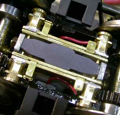
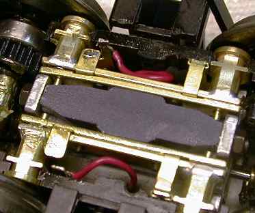
 This is the rear truck after I
reinstalled the Hillside power pickups and reinstalled the new
motor contacts to support the DCC equipped locomotive. The photo
has the same orientation as the other photo, the rear of the loco
is to the right. When I sent the trucks back to Bachmann, I took
out the Hillside contacts and reinstalled the original plastic ones
because I believe that Hillside may not still be in business. I
cannot find them on the net so that these contacts may not be
available.
This is the rear truck after I
reinstalled the Hillside power pickups and reinstalled the new
motor contacts to support the DCC equipped locomotive. The photo
has the same orientation as the other photo, the rear of the loco
is to the right. When I sent the trucks back to Bachmann, I took
out the Hillside contacts and reinstalled the original plastic ones
because I believe that Hillside may not still be in business. I
cannot find them on the net so that these contacts may not be
available.
It was a tedious job to reinstall the Hillside contacts, reinstall the separate motor contacts, reverse the wiring on the top covers and reinstall the trucks. However, it all worked.... for a while.
 After a few
minutes of running, the Shay started to sputter and then it stalled
completely with no power. After messing with it for awhile, it
became clear that the Hillside contacts were not working. The
plungers that press the ball bearing contacts against the wheel
backs were hanging up in a compressed state with the bearing nearly
fully retracted. If I touched them with a small screwdriver, the
contact would spring back into place, only to hang up again later.
This was happening to some extent on all 8 of them, some much worse
than others.
After a few
minutes of running, the Shay started to sputter and then it stalled
completely with no power. After messing with it for awhile, it
became clear that the Hillside contacts were not working. The
plungers that press the ball bearing contacts against the wheel
backs were hanging up in a compressed state with the bearing nearly
fully retracted. If I touched them with a small screwdriver, the
contact would spring back into place, only to hang up again later.
This was happening to some extent on all 8 of them, some much worse
than others.
I do not have a clue as to why this should start happening now as they had been very reliable before the truck change out. After examining the before photos and the current state, I couldn't detect a visual difference. In any event, I chucked up each contact in a drill bit and then ran it against a spinning grinding wheel chucked in a Dremel tool and tapered the end of the piston so that it could not hang up on the step inside the contact bore. This seemed to fix it and the Shay ran reliably for awhile, then it got flakey again.
This problem with the pistons hanging up in the contacts went away, but a problem still persisted. I pulled out the contacts once again and several of the ball bearings were stuck inside the contacts, NOT in a fully compressed state. The balls themselves were stuck. They would not even fall out when prodded. All the ball bearings are the same size, they are not too big and when reinserted, they seem to operate properly. Something is getting wedged in place.
I gave up and put the Bachmann contacts back in. These are of a newer design than the original ones. Instead of the ball and spring riding in a plastic bore in the contact housing, there is a brass sleeve that holds the ball and spring. I put the new ones back in the rear truck and it seemed to be fine using a Kadee contact brush. While installing the last front one, it broke and came apart in my hands. I recall that one of them was cracked when I pulled it out, this must have been the one. Anyway, a little patch with Zap-A-Gap fixed the plastic.
After all that, the Shay runs fine again, even on contaminated track. I had glued ballast yesterday and slopped glue mix all over the railheads. That didn't even slow the Shay down. It did develop a squeak sound after about a half hour of running. This was caused by the ball bearing contacts, a very small drop of conductive oil on each ball bearing stopped that and didn't impact the power pickup.
The last time a Shay busted gears, I send only the trucks back to Bachmann after removing my DCC specific wiring and returning it to the original configuration. They sent me new trucks of the same vintage that I had to modify again. Two years later, my other Shay broke the same gears. This time Bachmann insisted that I send them the whole locomotive. Since they would not understand the modifications that I made I was reluctant to do that. They wanted $50 to put new plastic trucks on it or $165 to replace them with new die cast trucks. However, I did not want them touching the loco. Just a new set of trucks purchased as parts would cost $265.
 Then I found a
used set of diecast trucks that had suffered some universal joint
damage for $45 for the set. I could use my old universals to
replace the broken ones. The coupler mounting bracket is similar
but the new one uses a very small machine screw instead of a much
larger self tapping screw. I'll either have to find some of the
metric screws or tap it out to a larger size machine screw.
Then I found a
used set of diecast trucks that had suffered some universal joint
damage for $45 for the set. I could use my old universals to
replace the broken ones. The coupler mounting bracket is similar
but the new one uses a very small machine screw instead of a much
larger self tapping screw. I'll either have to find some of the
metric screws or tap it out to a larger size machine screw.
 The die cast metal
truck wiring is different too. The truck has 4 contacts on top for
power pickups and motor leads so I won't have to rewire the
internals. However, I will have to cut some traces on the circuit
board in the truck cover and add two more wires as the motor and
track pickups are paralleled at this point.
The die cast metal
truck wiring is different too. The truck has 4 contacts on top for
power pickups and motor leads so I won't have to rewire the
internals. However, I will have to cut some traces on the circuit
board in the truck cover and add two more wires as the motor and
track pickups are paralleled at this point.
 There isn't much to do
in the bottom of the truck which is easily accessible. There are
lube plugs so that the gearing can be lubricated, with some
difficulty, without removing any screws. However, access is much
better with the bottom cover removed.
There isn't much to do
in the bottom of the truck which is easily accessible. There are
lube plugs so that the gearing can be lubricated, with some
difficulty, without removing any screws. However, access is much
better with the bottom cover removed.
 The gearing is
similar to the old truck too. This means that the plastic gears on
the axles will probably split some day too.
The gearing is
similar to the old truck too. This means that the plastic gears on
the axles will probably split some day too.
 The power contacts
are the little roller assemblies like I've seen on recent Bachmann
locos.
The power contacts
are the little roller assemblies like I've seen on recent Bachmann
locos.
One of them was flakey and tended to spit fire as I was testing the trucks by themselves. A little AeroCar "conductive" lubricant on the roller stopped that. I then lubricated everything in the trucks with more AeroCar lubes.
The instructions that Bachmann provided are clear, and replacement of the trucks with new ones would be pretty easy. My case will be a little more difficult because I have to deal with the parts that are missing from these used trucks and wiring it for DCC.
 This is the new
bolster after it has been modified to separate the motor and power
pickups. I drilled two small holes and cut two traces. The motor
wires that were already in the old bolster were fed through the
holes and soldered to the, now separated, motor contacts. The wires
that came on the bolster were spliced onto the original power
pickups wires, insulated with shrink tube and stuffed back into the
loco body. I did not have to actually open the loco body to make
this change.
This is the new
bolster after it has been modified to separate the motor and power
pickups. I drilled two small holes and cut two traces. The motor
wires that were already in the old bolster were fed through the
holes and soldered to the, now separated, motor contacts. The wires
that came on the bolster were spliced onto the original power
pickups wires, insulated with shrink tube and stuffed back into the
loco body. I did not have to actually open the loco body to make
this change.
The mechanical adaptation was actually pretty easy. These used bricks had been in an accident and both universal joints were broken. The U-joint itself is riveted together so instead of just replacing the missing square shafts with the ones from my old trucks, I replaced the whole shaft assemblies. They are the same. The gentleman that sold me the trucks is following up with the coupler brackets and the smaller screws. The old brackets would fit, but they are slightly wider than the newer ones and would need a washer under the screw head.
After the change out, I fired it up and it worked.
© 1997-2009 George Schreyer
Created Oct 10, 1997
Last Updated October 13, 2009