 This page is
dedicated to the details of one particular DCC/Sound decoder, the
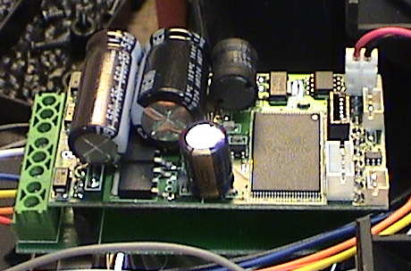
QSI Quantum Aristo. QSI
makes some HO sized decoders and just one model of a large scale
decoder, the Quantum Aristo. However it is a really good one that
seems to work just about anywhere. Nominally, it is "Plug-N-Play"
decoder intended to work in the DCC socket of AristoCraft
locomotives. However, it will also work in the sockets of some
Bachmann locomotives as well. It also has an adaptor board that
simulates the socket and converts the decoder to a screw connection
version. When the decoder is plugged into one of these adaptor
boards, it is called a "Quantum Magnum".
This page is
dedicated to the details of one particular DCC/Sound decoder, the
QSI Quantum Aristo. QSI
makes some HO sized decoders and just one model of a large scale
decoder, the Quantum Aristo. However it is a really good one that
seems to work just about anywhere. Nominally, it is "Plug-N-Play"
decoder intended to work in the DCC socket of AristoCraft
locomotives. However, it will also work in the sockets of some
Bachmann locomotives as well. It also has an adaptor board that
simulates the socket and converts the decoder to a screw connection
version. When the decoder is plugged into one of these adaptor
boards, it is called a "Quantum Magnum".
This is a full function DCC decoder with a 3 amp average motor
capability and an excellent integrated sound system. It has been
used on locos as large as an Aristo SD45 and many USA Trains locos
without blowing up. It will also work in much smaller locos where
it will physically fit. It will work on DC as well as DCC although
on track powered DC it will shut down when the track voltage gets
too low however there is a SuperCap kit for it that allows the
sound to continue for a few seconds after loss of track power. QSI
also makes a radio receiver that will plug into the decoder and
accept commands from an Airwire transmitter so that it can also
function under battery power.
There is just one model of this decoder used for both steam and
diesel. Depending on who you order it from, it may come with a
particular sound set pre-installed. The entire sound set and
decoder parameters can be reloaded into the decoder at any time
PROVIDED that the user has the Quantum programmer software and
interface. Firmware upgrades can also be installed via the
programmer. There is much more data in the sound set than just
sound. For SOME locomotives, QSI has determined an optimal set of
operational parameters that is included in the sound set so that
the user doesn't have to tweak these after the fact.
This page will be by nature limited in scope to straight up DCC
issues because I have no experience with it in DC or battery
powered modes. I will also not try to repeat information that is in
the manual except where I found it confusing. As of the creation
date of this page, I have three of these puppies, all steam, one in
a Bachmann Shay, one in a
recent Aristo Pacific and
one in an LGB 22232 0-4-0
switcher. A sample of the sound that the QSI makes can be found in this QuickTime video of the one in the Shay.
I felt that this decoder deserved it's own page just because it
is so different than a more standard DCC decoder. There are many
decoders that can just be described with a few specs, all the
details follow standards. This is good, with most other decoders,
an experienced DCC user doesn't even have to read the manual until
it comes time to tweak some manufacturer specific Configuration
Variable. The QSI decoder will work right out of the box as well
but to get the most out of it, it needs some tweaking.
The decoder comes with minimal instructions for programming. You
should download the ~250 page programming manual from the QSI web
site if you want to make any changes at all.
This decoder is not yet completely bug free, some things don't
seem to work quite right, but it can be made to work quite well
with some simple work arounds or programming adjustments.
Contents
Operational Characteristics
From a DCC throttle, the QSI works pretty much like any other
DCC decoder. It will respond to the throttle in a normal fashion
except that it comes programmed with an acceleration and
deceleration delay that comes along with it's default throttle
mode. It's functions also respond differently depending on if it
standing or moving. There are also some functions that change
depending on what it was doing previously. All this can be a bit
confusing at first blush, but you get used to it.
The 250
page instruction manual has the details of how the system works
and how to best take advantage of the features of the decoder. This link is to the Nov 2010 version, 4.6.1. If they update the manual the link will probably break. A revised link can be found at the QSI by following the Q2 link and looking on the right of the page for the new link.
Sound. The decoder's sound responds in synchronism to
throttle commands although the steam chuff can be controlled by a
cam as well. If the chuff rate doesn't match the loco speed very
well, it can be tweaked. The sound is fully digital and of very
high quality with lots of voices available. For example, the
cylinder cocks can be activated such that the cylinder blowdown
will play, in sync, for 16 chuffs or to 12 smph, whichever comes
first.
Lights. The lighting follows Rule 17 unless you change
it. The lights will be dim unless the loco is moving in the
direction of the light, when it will switch to bright. There are
parameters for changing how dim the lights are, but the bright
parameter seems to be set at max and does not appear to be user
changeable. The lights ramp from dim to bright slowly so that it
would not appear to be required to add resistors in series with
incandescent bulbs. The decoder gives them time to adjust. The
ramping is also a little easier on the bulbs than just being
slammed on or off. The "dim" setting defaults to 32 (range of 0 to
255). For an incandescent bulb, this can be roughly equal to "off"
but it works fine with LEDs.
BEMF. The decoder has back EMF capability that is enabled
by default. The mode that is active is called RTC, or Regulated
Throttle Control. This mode has loose BEMF coupling so that the
locos used in this mode will consist fairly well without serious
bucking. There are three other throttle modes as well but currently
two of them are disabled due to some patent issue with Mike's Train
House who claims a patent on some forms of BEMF control where there
is clearly prior art. I expect that this issue will be resolved
sometime, but it will take lawyers and courts to change it. The
other available throttle mode is STC, or Standard Throttle Control.
This essentially turns the BEMF off.
When in RTC, there are several BEMF parameters that can be
adjusted to change the performance of the BEMF system. There
appears to be a bug in the BEMF system so that in once case I had
to turn it off, see the Odd Behaviors section below.
Speed Control. The decoder has the capability, by reading
the BEMF signal, to determine the motor speed. If this is
calibrated by measuring the actual locomotive speed, the loco can
report its speed in miles per hour and it can use the actual speed
to trigger some sounds. The speed can also be matched to the
throttle setting such that 50% is also 50 smph.
Audio Feedback. Since this decoder has sound integrated,
it can report, via a recorded voice, what it is doing or the
results of programming. When you change a CV value in OPS mode, the
voice will report the CV being changed and the value that it
changed to. By entering a CV value into CV64, the voice will report
the current value without changing it. This makes programming on a
programming track unnecessary because the decoder can tell you what
it knows by audio feedback.
Function Outputs. The QSI has only two native function
outputs, F0f and F0r (white and yellow wire). These are all that
are implemented in the Aristo PnP interface. There is or will be an
accessory interface that adds more function outputs at extra cost.
Since most of the extra function outputs that I use on other
decoders go to controlling the sound system, the lack of these
extra outputs on the QSI is not all that important because the
sounds are already directly controlled by function keys. I
generally don't like to wire smoke through a decoder anyway and
things like the cab light and markers can be left on all the
time.
If you really need more function outputs, then for $17 you can
get a Digitrax or TCS function only decoder that provides 4
additional 250 mA functions with special effects.
Speed Matching. The QSI decoder has built in momentum, I
think to allow the sound and motion to better coordinate. This
complicates speed matching to other DCC equipped locos with other
kinds of decoders some, but not a lot. The standard speed matching
process applies. You can do this by programming on the main using
whatever OPS mode programming method your DCC system allows. This
method uses the "3 point" speed matching method which will work
just fine for the vast majority of cases. I've never had to use the
full 28 step table to speed match any locos well enough to consist
nicely. If you want to do 28 step speed matching, use Decoder Pro
in JMRI. Don't try to do it on a throttle.
- Place the locos on parallel tracks or one behind the other with
some space between them on the same, preferably level, track.
- Initially set CV's 2 through 6 to zero on both locos.
- CV2=0 sets the minimum starting voltage to zero
- CV3=0 sets the acceleration momentum to zero (on QSI to
minimum)
- CV4=0 does the same for deceleration
- CV5=0 sets the top speed to maximum
- CV6=0 sets the mid speed to the straight line mid point between
CV2 and CV5
- Set CV2 on both locos
- Increase the value of CV2 for each loco until the loco just
starts to move at speed step 1.
- Don't worry if the actual speed at speed step 1 matches unless
one loco is way off from the other one.
- Put the locos in a consist. This makes it easier to control
both their speeds at the same time.
- Run the throttle up to max and see which one is faster. If the
locos are on the same track and the faster one is the rearmost one,
run them in reverse so a gap opens between the locos.
- Set CV5 on the faster one to bring it down in speed to match
the slower one.
- Some decoders, especially Digitrax, behave oddly if BEMF is
enabled. CV5 may not be recognized unless CV6 is set too. In that
case, set CV6 to half of CV5.
- Keep adjusting the faster one to match the slower one at full
throttle
- Then set half throttle and adjust CV6 to match them at half
speed.
- You can either speed up the slower one or slow down the faster
one or both to your satisfaction
- Then set CV3 so that non-QSI equipped loco matches the speed up
characteristic of the QSI equipped loco
- Do the same with CV4 for the slow down characteristic
- At this point, the locos should be matched well enough to run
in a consist.
The QSI can be completely programmed from a full featured DCC
system like a Digitrax Super Chief but it takes the special
programming interface to change the sound file or update firmware.
I don't have the programming interface yet so that there is little
that I can say about it, BUT, there are some things I know.
Progrmming Interface and Software. The QSI software works
in conjunction with a hardware interface. The software can be
downloaded and some of it's functions used without the interface.
The major function is to preview sound files see what you will get
when you order it with a particular sound file. Sound files are
also downloadable free. When a computer is connected via the
programming interface to a decoder, all of the programming of CVs
can be done via the software interface. This makes massive changes
to the CVs much easier.
Macintosh Compatibly. The rub here is that the software
is released ONLY for Windows. This is a problem for me because I
don't have a Windows PC, my household is 100% Macintosh. However,
there are three ways around this issue.
-
Boot Camp is Apple's way of running PC software on an
Intel based Macintosh. Basically, Boot Camp facilitates setting up
a PC partition on the Mac disk. You have to BYO version of XP SP2
or Vista but Boot Camp allows a full up Windows install in a new
partition. Boot Camp creates the new partition (without having to
reformat the disk) and creates an installer CD with all the
necessary drivers to make the Apple hardware work under Windows.
You basically boot your Windows installer disk and do a regular
Windows install, then use the CD to install the drivers. Then you
have a full up PC. When the computer boots, the user gets to select
which OS to boot into. When booted as a Mac, the Windows system is
not accessible. When booted as a PC, Windows takes over and the Mac
partition is not accessible. At this point, you have a PC that
comes with all the liabilities that Windows brings with it. Some
have reported that a Macintosh booted into Windows makes a better
PC that most dedicated PCs. I don't have XP SP2 or Vista so I don't
use Boot Camp.
-
Parallels is a virtualization system that runs in Intel
based Macintoshes. Basically, you launch Parallels under the Mac OS
and it then creates a virtual machine in which to boot Windows or
some other OS. The other OS then runs in a window along side the
other Macintosh windows. Copy/Paste works between OS's. Parallels
will work with Linux, DOS or any version of Windows. I have a copy
of W2K that I use to run the QSI software and it works, at least
the part that allows sound file previews does. The Phoenix
programming interface, which I do have, works fine under Parallels.
There is also a product called VMWare Fusion which does much the
same thing as Parallels and would probably work too. Parallels
costs $80.
-
CrossOver is a entirely different beast. CrossOver is
basically a nice GUI on top of Wine. Wine is an open source project
that emulates Windows APIs (Application Program Interface) on Unix
based systems (which include Linux) such that a PC program can be
executed directly by the Unix system. The Macintosh OS is Unix
underneath a very good GUI. CrossOver intercepts the calls to
Windows services and translates them to Unix calls. Crossover will
not run with all PC applications, only ones that are "clean" and
make all of their calls for system resources through the published
APIs. The QSI software is in this class, and at least as far as the
sound previews go, it works.
I expect that eventually, I'll buy the programming interface
since I now have three of these puppies to support and I am
sufficiently impressed with the QSI decoder to be inclined to buy
more when I need both motor control and sound for a new
installation.
DCC Throttle Programming. DCC decoders are usually
programmed via CVs, or Configuration Variables. A CV is an 8 bit
memory location in the decoder which is non-volatile. Once a CV is
set, it stays that way until it is explicitly changed. The decoder
uses the data stored in the CVs to define many of it's operating
characteristics. Many of them are predefined in the NMRA standard
and the QSI follows the standard.
There is a small range of CVs, 49 through 64, which are defined
to be manufacturer specified. What these do is entirely dependent
on who made the decoder and these are the only ones I'll be dealing
with here.
There are only 16 of these CVs so that this tends to constrain
what custom things a decoder can do without some kind of special
tricks. QSI is REALLY tricky here, they have managed to expand
these 16 locations into hundreds of CVs by the definition of two
modifier CVs. CV49 is called the Primary Index or PI. It acts like
a shift key with up to 256 values. CV50 is the Secondary Index or
SI. It can also take on 256 values. With these two modifiers, the
remaining 14 CVs could be expanded into hundreds of thousands of
CVs but QSI has not applied these shift codes to the whole range.
Some of them are defined using only the PI, some are defined with
both the PI and SI, some are reserved for future use and some are
not modified at all by the PI and SI. Still, there are more CVs
available than you can shake a stick at although getting to some of
them may require setting the values of THREE CVs to enter just one
value.
When a CV is listed in the manual as CVxx.yy.zz this means that
to get to it, CV49 must contain the value yy, CV50 must have the
value of zz (if given) and the actual data to be entered goes into
CVxx. This may seem pretty convoluted, but it is necessary to
create spaces for all the data that is needed to customize the QSI
decoder within the constraints of the NMRA specification.
Fortunately, while in OPS programming mode, the address and
value of the CV that you THINK that you are programming is reported
by voice. By entering the address of another CV into CV64, the
decoder will report only the existing value of the CV with the
current PI and SI that are in effect.
If you try to program a CV with an illegal or unimplemented
value then the voice will report the CV number WITHOUT a value or
not report anything at all. Then you know that the programming
attempt didn't "take" and you need to figure out why it didn't
work. In my experience, this usually comes from trying to stuff a
value into the wrong CV or by using an illegal or unimplemented
value to the correct CV.
QSI's programming interface and software make programming these
special CV's much easier than doing it on a throttle. Also, JMRI is aware of the CV
structure of QSI decoders and also makes CV programming of the
manufacturer specific CV's much easier. JMRI will run on a PC, Mac
or Linux.
I've come across a few issues with the QSI, one I think is a
bug, one was just unexpected and one is a drawing error.
BEMF Issue. When I installed a QSI into the LGB 0-4-0, it
didn't work properly. Going forward, the loco would not stop when
commanded to zero speed. It was just crawling along making a mild
buzzing sound. If I interrupted the motion of the loco with my
finger, it would stop until started again. It didn't do the same
thing in reverse. It was clear that the BEMF system was bumping it
along but it SHOULD have been expecting zero back EMF. Maybe it
cannot detect the very low value of BEMF generated by this motor at
that speed and it THOUGHT that the loco was actually stopped. All
manner of playing with the BEMF parameters didn't help. I "fixed"
it by enabling the STC mode where BEMF is turned off. Then the loco
behaved fine. This loco doesn't need BEMF anyway. Someday there
will probably be a firmware update to deal with this.
Headlight Operation. The manual indicated that the
headlights should follow Rule 17 dimming. In this case, they were
programmed to be on bright when moving in the appropriate direction
and dim when standing or going in the other direction. My lights
were "off" when they should have been dim. I didn't think too much
of it until I changed the headlight on the LGB loco to an LED. THEN
it was dim. The rear headlight was still a bulb and it was off,
even in a very dark room, there was no visible light coming off the
"dimmed" bulb. It occurred to me that the "dim" setting was not
bright enough for the filament of the incandescent bulb to reach
about 900°C where it would be hot enough to radiate in the
visible spectrum. A quick check with an IR thermometer indicated
that the bulb was slightly warm, but just not visible. I bumped the
intensity of the rear headlight from the default of 32 to 64 and
now it runs dim, as described in the manual. This is probably why
the incandescent lights in the Pacific and Shay also appear to be
off when they should be dim. The front LED on the LGB loco was
actually brighter than I wanted in the "dim" mode so I turned it
down to half.
Screw Terminal Labels. The optional screw terminal
adaptor board has eight screw terminals that are identified by a
stencil pattern printed on the board. These appear to be correct.
However, as I read the diagram that comes with the decoder, the
location of the blue wire and the headlight identification is
incorrect. If you follow the documentation, the lights won't work
because they will be connected to ground instead of the +common or
blue wire.
Physical Size. This is physically a large decoder,
primarily in the thickness dimension when the adaptor board is
added. This is due to the length of the pins for the PnP socket and
to the size of some of the components on the board itself. While
the adaptor board can be cut off right next to the 12 pin header
row to make it a little smaller, it is still pretty big. It can be
a challenge to find room for this puppy in some constrained
spaces.
The QSI is a well featured decoder, but it still doesn't allow
some of the customization that other decoders and sound systems
do.
Bell Ring Rate. I'd like to be able to adjust the ring
rate of the bell, there doesn't seem to be a way to do that now.
The bell simulates a fairly fast automatic ringer. I'd like to slow
it down AND to optionally make the ring rate somewhat random as if
a bored fireman was pulling on the bell rope. With the aid of the
programmer, it is possible to upload different bell sounds with
different ring rates. Some sound profiles have multiple bell
sounds. However, if a bell provided isn't what you want and you
don't have a programmer, then you are SOL.
Automatic Start and Stop Signals. The Soundtraxx Sierra
sound system can be configured to make some automatic whistle, bell
and air release sounds when it starts and stops. The Phoenix P5
does similar automatic signals. The QSI has automatic modes for
many of it's sounds, but not these. I'd like the option of setting
it up similarly to the Sierra where it blows two toots when
starting forward, three toots when starting in reverse, plays the
bell up to a preset speed and then blows one toot at stop with an
air release.
Whistle Sounds. If F2 is pressed momentarily, the system
will play a short whistle toot. If F2 is held down longer, it will
play an extended blast for as long as the button is held down. This
works pretty well, but you have to be quick to get the short toot.
The problem is that in some sound sets, the short toot sounds like
it is coming from a different whistle than the longer ones, the 505
set is an example. In the 500 sound set, the short and long toots
at least sound the same except for duration. This should be
fixed.
RDC Sound files. The Budd RDC used a hydraulic torque
converter transmission and a 225 hp diesel engine driving each
truck. They sounded much different than a "regular" diesel
locomotive because they don't "notch" like most diesel electric
engines do. The engine speed ramps up, but not as fast at the RDC
speed changes.
Goose Sound files. There isn't a gas-mechanical sound
file available for the QSI, at least not yet.
This page has been accessed  times since 11 Nov 08.
© 2009 George Schreyer
Created 11 Nov 08
Last Updated October 14, 2009
 10 Oct 09