 I picked up an LGB loco at the
2008 SoCalGRS annual meeting. It
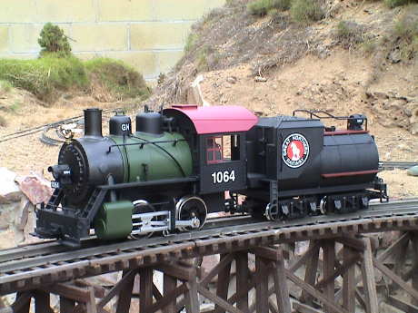
is an LGB 0-4-0 and Vanderbilt tender carrying an Great Northern logo.
This engine came equipped with sound, smoke, lights and is supposed to
be DCC ready. As soon as I got it home, it went on the track for a test
run. All seemed to be reasonably well. The rest of this page describes
the loco in some finer detail as well as the modifications that were
performed, some of them happened virtually immediately.
I picked up an LGB loco at the
2008 SoCalGRS annual meeting. It
is an LGB 0-4-0 and Vanderbilt tender carrying an Great Northern logo.
This engine came equipped with sound, smoke, lights and is supposed to
be DCC ready. As soon as I got it home, it went on the track for a test
run. All seemed to be reasonably well. The rest of this page describes
the loco in some finer detail as well as the modifications that were
performed, some of them happened virtually immediately.
The loco represents one of the many thousands of 0-4-0 switchers
built over a period of about 100 years. This one is modeled after a
loco made in the latter part of that period as it carries a dynamo. The
overall scale is debatable. To me, it looks kind of squished in the
length dimension.
The loco runs quite well, although there are always improvements
possible.
Contents
The engine and tender carry fair detail. The grabs are all metal but
the siderods are plastic and there is no valve gear. The backhead
detail is cast in place but there are some valve handles attached in a
few spots. The headlights are directional. There is one lonely valve on
the running board on each side, I don't know which of the dozens of
valves that might be found on a real loco that these two valves are
supposed to represent.
There is a 4 position switch on the backhead which can be used to
turn various combinations of motor, lights, smoke and sound on or off,
but if you want sound, you get everything else too. If you want the motor, you get the cab lights and smoke too.
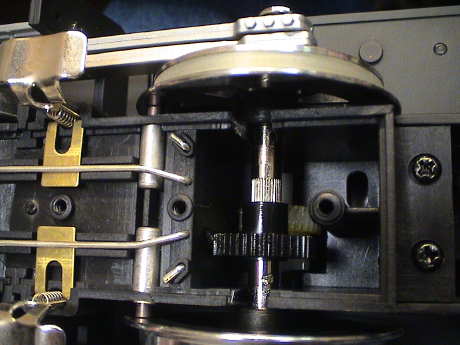 The motor brick has
a dual reduction gearing setup. There are also indications that the
power pickups and the motors are brought up to the inside of the loco
separately.
The motor brick has
a dual reduction gearing setup. There are also indications that the
power pickups and the motors are brought up to the inside of the loco
separately.
There is an electronic sound system built into the tender. It does a
good job at the chuff, bell and whistle. I heard no other sounds. The
bell and whistle are triggered via (supplied) track magnets interacting
with a magnetic pickup on the front truck of the tender. The
instructions indicate that the tender can accept a DCC decoder to
trigger the sounds as well.
The chuff rate control is electronic, at very low speeds, it
produces four chuffs/driver revolution but it doesn't follow changes in
speed very well. At the higher speeds, it's hard to tell if the chuff
rate is correct.
The engine has a standard LGB (Seuthe) smoke unit which is
essentially on all of the time. The instructions indicate that the
smoke unit can be run dry without damage.
The unit smokes stongly BUT if has just been filled, if probably won't smoke at all because the last drop of smoke fluid is plugging the exit hole on the stack. Poke a twig or toothpick in the hole in the top of the stack to break up the droplet so that the smoke can escape.
During the conversion to DCC, some of the functions of the switch have changed. Since the decoder controls most of the action, it doesn't matter what position the switch is in EXCEPT that the leftmost position turns off the cab light and smoke unit.
LGB cautions that the loco should be run ONLY from LGB power packs
or the manufacturer's warranty would be voided. Since LGB went out of
business, I suspect that the "warranty" has already expired. I ran it
from a Train Engineer set both to Linear and PWC modes. There didn't
seem to be a lot of difference, it ran fine on both.
As is typical for LGB locos, it runs very quietly. I detected no
unusual sounds and the mechanism noise is barely perceptible.
The tender had an unnerving tendency to wobble back and forth and
sometimes run "crabbed" across the track. This was due to a large
amount of slop in the tender axles. It took 2 nylon shims on each side
of each axle to control this tendency.
At 20 volts on the track, the loco goes a little faster than a real
0-4-0 would likely be run. I estimate the top speed at about 50 smph
depending on what scale the loco really is. This is not totally
unreasonable.
The loco is NOT a very strong puller, but that is expected of a such
a small loco. It will pull 5 large cars on my 1.6% ruling grade which
makes it one of the weaker pullers in my stable. However, it doesn't
slurp down a lot of juice doing it. Even at full slip, the loco draws
only slightly more than an amp, and that is WITH the smoke unit
running. Full hard stall is 3 amps.
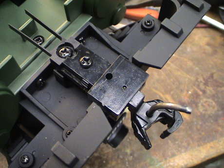 In order to run the
tractive effort and current consumption tests, I need to jettison the
supplied hook and loop couplers and install Kadee couplers. The Kadee
#831 is designed for truck mounting and it fits well at both ends. I
choose to cut the ends of the mounting tangs off both ends to get the
couplers to mount inward a bit. On the engine front coupler, the side
to side travel is about the same mounted either with the stock tang or
a shortened tang as the coupler box interferers with the front step
after only a little rotation in either case. This is now, in effect, a
body mount.
In order to run the
tractive effort and current consumption tests, I need to jettison the
supplied hook and loop couplers and install Kadee couplers. The Kadee
#831 is designed for truck mounting and it fits well at both ends. I
choose to cut the ends of the mounting tangs off both ends to get the
couplers to mount inward a bit. On the engine front coupler, the side
to side travel is about the same mounted either with the stock tang or
a shortened tang as the coupler box interferers with the front step
after only a little rotation in either case. This is now, in effect, a
body mount.
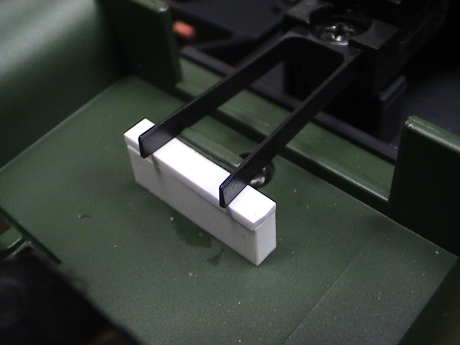 This
mount has a little vertical slop that is not acceptable for a Kadee
coupler. The coupler needs to be held at its highest position for
proper operation. This is easily accomplished with the addition of the
white shims under the ends of the centering springs. I used a total of
0.310" of shim, maybe a little less would do as well. This holds the
springs down and therefore the coupler is held up.
This
mount has a little vertical slop that is not acceptable for a Kadee
coupler. The coupler needs to be held at its highest position for
proper operation. This is easily accomplished with the addition of the
white shims under the ends of the centering springs. I used a total of
0.310" of shim, maybe a little less would do as well. This holds the
springs down and therefore the coupler is held up.
 On the tender, it
is a full truck mount. I also cut the tang back so that I could use the
original mounting hole for the original screw. There used to be a dummy
coupler mounted on the rear beam above the hook and loop. It came off
right away.
On the tender, it
is a full truck mount. I also cut the tang back so that I could use the
original mounting hole for the original screw. There used to be a dummy
coupler mounted on the rear beam above the hook and loop. It came off
right away.
Power is picked up on the loco only on 4 wheels and 2 sliders,
however one of the drivers has a traction tire so that limits it's
power pickup pretty significantly.
Although my track is pretty dirty as it has been raining a little
recently, the engine ran on it, but not all too well. It spit and
sputtered in spots and stalled a couple of times. This is about the
same performance as my LGB
2060 which has essentially the same pickup arrangement. Overall,
the limited power pickup is not adequate for use on pretty dirty track.
I ran my track cleaning car around three times to sweep off the loose
stuff and then the engine by itself ran pretty well but the headlight
still flickered in spots and the loco wanted to stall on switch frogs.
But I don't keep my track in pristine condition so that I'll be adding
power pickups to the tender shortly.
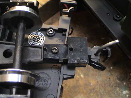
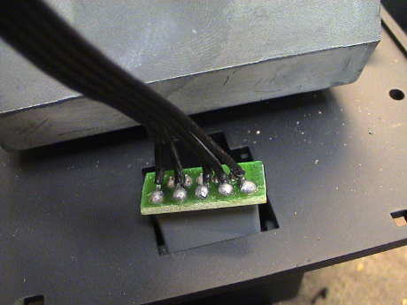
 I used
some extra LGB contacts that I had and attached them to the topside of
the reed switch assembly on the front tender truck. In this photo, I
have clamped a pair of contacts while the tack adhesive, Zap-A-Gap,
sets up. Later, I reinforced the joint with two-part filled epoxy.
I used
some extra LGB contacts that I had and attached them to the topside of
the reed switch assembly on the front tender truck. In this photo, I
have clamped a pair of contacts while the tack adhesive, Zap-A-Gap,
sets up. Later, I reinforced the joint with two-part filled epoxy.
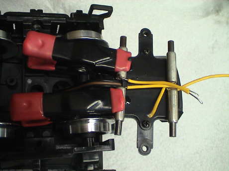
 After
the epoxy had set and the reed switch assembly was replaced, the
contacts are tucked up out of the way. The wires run up the hole in the
tender floor and run back to the connector at the rear of the tank. The
contact on this connector that is on the engineer's side is also the
one that eventually works it way to the loco, also on the engineer's
side.
After
the epoxy had set and the reed switch assembly was replaced, the
contacts are tucked up out of the way. The wires run up the hole in the
tender floor and run back to the connector at the rear of the tank. The
contact on this connector that is on the engineer's side is also the
one that eventually works it way to the loco, also on the engineer's
side.
A quick test on the layout showed that there was a major
improvement. The headlight flickering was completely gone and there was
no problem with switch frogs. I ran the engine on a section of track
that hadn't been cleaned in a month or so and it also ran well,
although there was a little headlight flickering in a few spots.
Overall, this is a good deal.
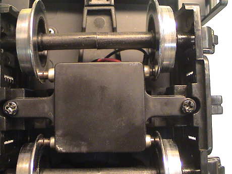
 After I bought some more LGB type contacts (from Massoth), I installed a set on the rear tender truck as well. The loco wasn't really hurting for power pickup, but more is better. These were attached to a 1.45" square piece of 0.060" stryene sheet with Zap-A-Gap CA to hold them in place and then reinforced with epoxy. Now the loco picks up power on 12 wheels and 2 sliders.
it is possible to get into both the loco and tender without a lot of
difficulty but there are several screws that have to be removed in
either case.
 To get
this far, remove the coal load (2 screws on top) and then two more
screws under the 9 volt battery. Then the coal bunker can be removed
exposing the front of the tender's PWB.
To get
this far, remove the coal load (2 screws on top) and then two more
screws under the 9 volt battery. Then the coal bunker can be removed
exposing the front of the tender's PWB.
 Removal of
6 more screws under the front part of the tender tank (two of them are
next to the electrical connector to the loco) will allow the coal
bunker and part of the water tank to be removed but this is not really
necessary to access the whole PWB. Just remove four screws under the
rear portion of the water tank to free it. Note that the front half of
the tank must be at least loose to get the back half off. This exposes
the full area of the PWB. The tender board contains the sound
system.
Removal of
6 more screws under the front part of the tender tank (two of them are
next to the electrical connector to the loco) will allow the coal
bunker and part of the water tank to be removed but this is not really
necessary to access the whole PWB. Just remove four screws under the
rear portion of the water tank to free it. Note that the front half of
the tank must be at least loose to get the back half off. This exposes
the full area of the PWB. The tender board contains the sound
system.
 The loco is a little
easier to get into. First, remove the handrails along the sides of the
boiler. Then remove 4 screws under the cab and pull it straight up.
Then remove two screws at the sides of the backhead and that will come
off. Then two more screws underneath the front part of the boiler will
free it. Then the whole of the PWB in the loco can be seen.
The loco is a little
easier to get into. First, remove the handrails along the sides of the
boiler. Then remove 4 screws under the cab and pull it straight up.
Then remove two screws at the sides of the backhead and that will come
off. Then two more screws underneath the front part of the boiler will
free it. Then the whole of the PWB in the loco can be seen.
The engine and tender are interconnected with a 5 wire harness.
There is a fairly complex PWB in both units, too complex to trace out
due to all the surface mounted parts and integrated circuits. I did
determine that the outer pins of the loco to tender harness are track
power. These lead all the way to the connector at the rear of the
tender. The loco can be powered via the connector on the back of the
tender.
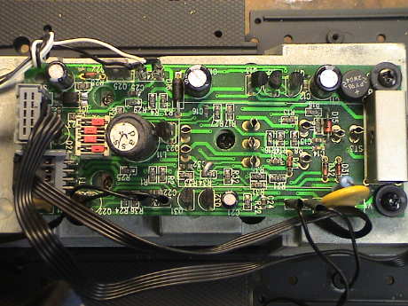
 Both PWBs
are supposed to contain connections for a DCC decoder, I assume that
these contacts are the ones but without some installation instructions,
it could be pretty hard to figure out which is which.
Both PWBs
are supposed to contain connections for a DCC decoder, I assume that
these contacts are the ones but without some installation instructions,
it could be pretty hard to figure out which is which.
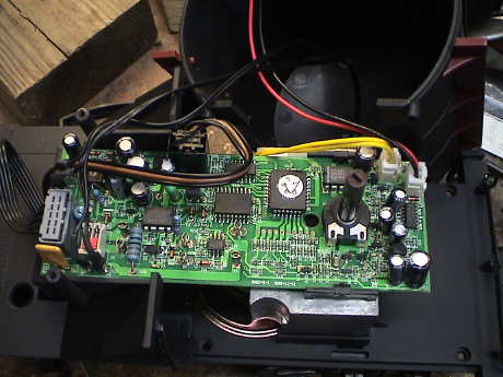
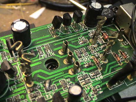
 This is a photo of the loco
board. There are 9 contacts on the board that are designed to accept
the mating pins of a DCC decoder designed for this kind of loco. I've
traced the function of the most important ones, but the other 5 have
eluded me.
This is a photo of the loco
board. There are 9 contacts on the board that are designed to accept
the mating pins of a DCC decoder designed for this kind of loco. I've
traced the function of the most important ones, but the other 5 have
eluded me.
At the lower left is the 4 pin connector to the motor block. The
outer pins are for the motor, the inner ones are for the track power
pickups.
The item in the left center is a 4 pole switch. This is there to
allow reconfiguration of the PWB for DCC. All of these switches should
be set to the right (rearward) for regular track power operation. I
think that they should all be set to the left (forward) for DCC. The
functions of these switches is as follows:
Switch 1 has something to do with the headlights
Switch 2 disconnects one motor lead from the rest of the board
Switch 3 disconnects the other motor lead
Switch 4 disconnects the lights
I have not yet determined what controls the lighting when switch 4
is set for DCC. Also, the headlight behavior is funny. If I turn switch
4 to the DCC side, none of the lights work. If I leave switch 4 to the
DC side and move switch 1 to the DCC side, I can make the headlights do
something, but it is odd. If the pin marked "Headlight ??" is grounded
(back to the track via a pair of diodes as a DCC decoder would do it)
then the front headlight comes on. With the pin ungrounded, the rear
headlight comes on. The direction that the motor is running doesn't
have any impact.
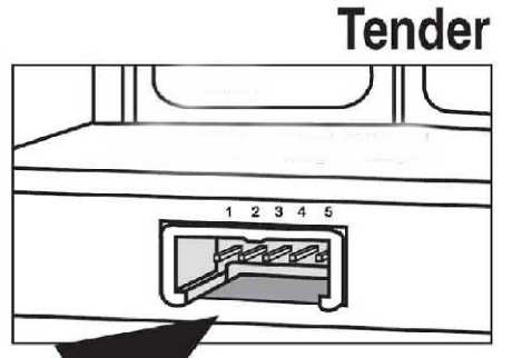 At the upper left is the connector
for the 5 pin harness that leads to the tender. The definition of these
pins, shown in the following paragraph, was drawn by Stan
Cederleaf.
At the upper left is the connector
for the 5 pin harness that leads to the tender. The definition of these
pins, shown in the following paragraph, was drawn by Stan
Cederleaf.
Pin 1 = Track Power Right (constant to rear outlet)
Pin 2 = Rear Light Common
Pin 3 = Rear Light
Pin 4 = Switched Track Power Right (for soundboard power only)
Pin 5 = Track Power left (to rear outlet and soundboard)
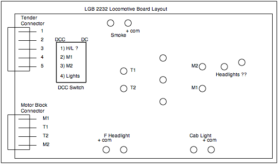 This is a
partial layout diagram for the connections to the board in the loco.
The motor and track connectors were easy to determine. I have not
determined the functions of the other 5 connections. Note that the
lighting and smoke unit are all joined with a + Common trace. The
weight under the board is ALSO + Common, be careful what touches it. +
Common on my loco is about 6.4 volts.
This is a
partial layout diagram for the connections to the board in the loco.
The motor and track connectors were easy to determine. I have not
determined the functions of the other 5 connections. Note that the
lighting and smoke unit are all joined with a + Common trace. The
weight under the board is ALSO + Common, be careful what touches it. +
Common on my loco is about 6.4 volts.
I did not find an obvious system ground (- Common) trace on the PWB
so I synthesized one from two diodes to the track contacts for testing
purposes. I find that if the non-common headlight lead is unplugged and
grounded, it will operate properly UNLESS the switch on the backhead is
set to OFF (position 0). Then the headlight voltage can INCREASE to
track voltage and it gets really bright. This is not good.
The instruction booklet that came with the set indicates that the
loco and tender are DCC ready. I would guess that it is intended to
install a function only decoder in the tender to drive the sound system
and a motor and lights only decoder in the loco body to drive the
motor. There is a 4 pole DIP switch on the board to reconfigure the
wiring to isolate the motor and accept a decoder. LGB made, and Massoth
still makes, a decoder that has pins on it that will plug right into
the sockets on the board. That is why the sockets are unlabeled. There
is no need to label connections that are made in masse by the
connection of a mating assembly.
The LGB and Massoth (and perhaps a Zimo) decoders also understand
the funny serial command string that was originally designed into the
MTS system. To activate functions, F1 was toggled some number of times
to activate a given function. Apparently, the decoders designed for
this loco interpret standard DCC function commands and translate these
into a series of pulses on the F1 pin to emulate "normal" DCC function
operation. I don't think that this loco can actually do anything with
functions past F0. On this loco, the F1 pin appears to just toggle the
direction of the headlight in a non-standard fashion. I don't want to
mess with this.
Some form of documentation would go a long way in making a DCC
installation easier for a DIY guy. LGB did not provide these
instructions because they wanted the user to send the loco in for the
installation of an LGB approved decoder. This is not possible now, but
a DIY installation of a Massoth decoder would be very easy, plug it in
and flip the four switches.
Alternately, I could just jettison the all the internal electronics
an use a QSI sound decoder, perhaps with LED's instead of the
incandescent bulbs. The 5 wire harness to the tender could bring
forward track power from tender pickups and send the speaker signals
back to the tender. The rear headlight could operate off the 5th wire
if a "blue" wire is synthesized in the tender with a couple of diodes.
Alternately, the decoder mounting position could be reversed by putting
it into the tender. Then two wires send track power forward, two more
would send motor power forward and the 5th one would be used for the
front headlight with the "blue" wire synthesized with two diodes in the
loco.
I could also retain the loco board to provide the power for the cab
light and smoke unit. I've found the track and motor terminals on the
board so that I could reassign the 3 center wires on the tender harness
and use wires 2 and 4 for the motor power forward to the loco and wire
3 for the headlight control going back to the tender. I would change
out the headlights to LEDs and wire them directly to the decoder. This
wiring change would be quite easy to do by simply unsoldering the
tender harness on the back of the connector inside the loco and then
tapping off those three wires. New wires would be soldered to those
points to go where they need to go.
Update, Nov 8, 2008. This is the route that I have elected to take.
I'll leave the loco pretty much intact with no changes to the PWB at
all. A QSI DCC sound decoder and screw terminal board that arrived
today will go into the tender and I'll sell the existing LGB sound
board.
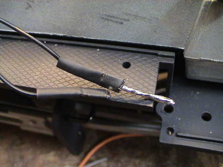
 The 5 wire connector
at the rear of the loco comes out of the frame easily. I'll lift the
center 3 wires and insulate them with shrink tube. Different wires will
be soldered to these three pins.
The 5 wire connector
at the rear of the loco comes out of the frame easily. I'll lift the
center 3 wires and insulate them with shrink tube. Different wires will
be soldered to these three pins.
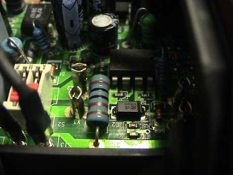
 The wires
from pins 2 and 4 will solder to these Molex Series 062 connector pins
that just happen to fit into the sockets on the loco's PWB. The two
pins to the right are the motor pins when switches 2 and 3 on the DIP
switch are pushed forward. DIP switches 1 and 4 will be left in the
rearward, or track power, position. This lets the loco board create
power for the cab light and smoke unit, yet also allows them to be
turned off with the slide switch on the backhead.
The wires
from pins 2 and 4 will solder to these Molex Series 062 connector pins
that just happen to fit into the sockets on the loco's PWB. The two
pins to the right are the motor pins when switches 2 and 3 on the DIP
switch are pushed forward. DIP switches 1 and 4 will be left in the
rearward, or track power, position. This lets the loco board create
power for the cab light and smoke unit, yet also allows them to be
turned off with the slide switch on the backhead.
The two Molex pins on the left are track power. One diode will be
soldered to each track power pin and then soldered together to make a
"blue" wire that carries full rectified track voltage.
 The two
headlight connectors used to fit over pins on the PWB. A 16 ga wire
emulates the pin well enough so that I don't even have to cut off the
connectors. One headlight wire goes to the "blue" wire, the other gets
wired back to the center pin on the loco connector through a 330 (or
maybe 390) ohm resistor. I'll check the headlight voltage when I am
done and adjust the resistor as needed. If I elect to change the
headlight to an LED, the resistor increases to 820 to 1000 ohms.
The two
headlight connectors used to fit over pins on the PWB. A 16 ga wire
emulates the pin well enough so that I don't even have to cut off the
connectors. One headlight wire goes to the "blue" wire, the other gets
wired back to the center pin on the loco connector through a 330 (or
maybe 390) ohm resistor. I'll check the headlight voltage when I am
done and adjust the resistor as needed. If I elect to change the
headlight to an LED, the resistor increases to 820 to 1000 ohms.
The tender will be gutted. I'll retain the rear headlight and treat
it the same as the one in the loco. I'll also change out the speaker
for a better one. I'll retain the 5 wire harness but cut off the end
that goes to the sound board and terminate the 5 wires to the decoder
as needed. Since I'm using the reed switch assembly to support power
pickups, I'll cut it's harness and send it off with the sound
board.
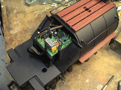
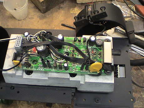
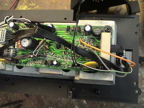 This is the converted loco
after a few minutes work. It is wired as described above and presented
no difficulties.
This is the converted loco
after a few minutes work. It is wired as described above and presented
no difficulties.
The two diodes that synthesize the decoder blue wire are visible in
the contacts plugged into the track power jacks. The orange and gray
wires are the motor wires.
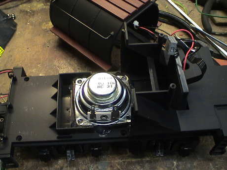 The QSI decoder would not
fit on top of the weight in the tender and my replacement speaker would
not fit under the weight so that weight went overboard. If I need
weight to keep the tender on the track, I'll glue some to the floor
behind the speaker. For the time being, it'll run light.
The QSI decoder would not
fit on top of the weight in the tender and my replacement speaker would
not fit under the weight so that weight went overboard. If I need
weight to keep the tender on the track, I'll glue some to the floor
behind the speaker. For the time being, it'll run light.
These speakers come with an adhesive backed foam seal. It is stuck
to the floor with it's own adhesive and the speaker is hot glued to the
foam seal.
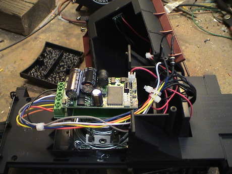 The QSI and it's screw
adaptor board are mounted on the back of the speaker with double backed
foam mounting tape. It clears the inside of the tender shell by about
half an inch. The rear headlight is wired directly to the decoder
through a 390 ohm resistor. The motor and front headlight leads go
forward to the loco.
The QSI and it's screw
adaptor board are mounted on the back of the speaker with double backed
foam mounting tape. It clears the inside of the tender shell by about
half an inch. The rear headlight is wired directly to the decoder
through a 390 ohm resistor. The motor and front headlight leads go
forward to the loco.
The QSI provided documentation and the stencils on the screw adaptor
board don't agree with one another. It could be that I am
misinterpreting the diagram, but I am trained to read engineering
drawings. I followed the stencil on the board and it worked
properly.
It all ran well except that I had a problem with the Regulated
Throttle Control (BEMF) mode. The loco did not want to stop going
forward until it stalled against something. It would stop going in
reverse. It would just creep along with the throttle set at zero. I
tried massaging the BEMF settings but I could not get it to stop
properly. I turned the BEMF off by changing the operating mode to
Standard Throttle Control (STC) and the problem went away.
I had to reset CV56.13 to get the chuff to beat at the correct rate,
it was going about twice too fast.
This QSI decoder has the "500" sound file with a peep-peep standard
whistle. There is also a lower note more standard whistle enabled by
F11. Both of these whistles play manually quite well with the short and
long toots having the same tone. This is unlike the program that came
in the QSI that went into the new Pacific.
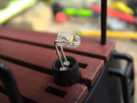
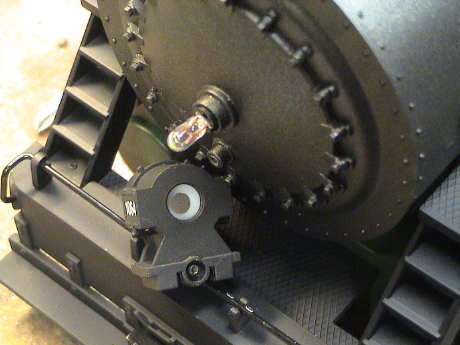 The stock headlight
is a 6 volt incandescent bulb. It fits in a small socket on the front
of the smokebox. The headlight housing simply fits over the bulb. It is
held on with one screw that can be accessed by removing the number
plate. The bulb is fairly bright as bulbs go and it spreads light
around well, it can be seen in daylight, but it doesn't cast much of a
beam.
The stock headlight
is a 6 volt incandescent bulb. It fits in a small socket on the front
of the smokebox. The headlight housing simply fits over the bulb. It is
held on with one screw that can be accessed by removing the number
plate. The bulb is fairly bright as bulbs go and it spreads light
around well, it can be seen in daylight, but it doesn't cast much of a
beam.
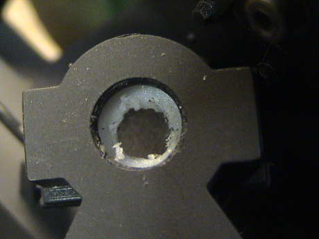 It turns out that a
5 mm LED will fit right in the socket if the leads are clipped short.
The white plastic cup inside the headlight housing is about 4.5 mm in
diameter so it needs to be enlarged just a little to allow the LED
housing to poke into the headlight housing. Since this cup is loose
inside the headlight housing, it a little difficult to drill it, but I
just worked with at an angle with a 0.200" drill bit by hand and
managed to gouge enough plastic off to allow the LED to fit.
It turns out that a
5 mm LED will fit right in the socket if the leads are clipped short.
The white plastic cup inside the headlight housing is about 4.5 mm in
diameter so it needs to be enlarged just a little to allow the LED
housing to poke into the headlight housing. Since this cup is loose
inside the headlight housing, it a little difficult to drill it, but I
just worked with at an angle with a 0.200" drill bit by hand and
managed to gouge enough plastic off to allow the LED to fit.
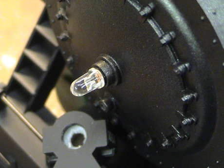 A white LED wants to
draw 20 mA or so which results in about a 3 volt drop, too small for
the stock loco lighting circuit. If the LED goes in to an unmodified
loco, one of the wires needs to be clipped and a 150 ohm resistor
installed in series with the LED. Normally, the longer lead on an LED
is the positive one, but if you've already clipped them, the positive
lead is the one with the smaller electrode as viewed through the side
of the LED housing.
A white LED wants to
draw 20 mA or so which results in about a 3 volt drop, too small for
the stock loco lighting circuit. If the LED goes in to an unmodified
loco, one of the wires needs to be clipped and a 150 ohm resistor
installed in series with the LED. Normally, the longer lead on an LED
is the positive one, but if you've already clipped them, the positive
lead is the one with the smaller electrode as viewed through the side
of the LED housing.
For a DCC installation where the source voltage is on the order of
18 to 20 volts, a 750 to 1000 ohm resistor is appropriate in series
with the LED.
This is a "warm white" 20 degree high intensity LED and it makes an
excellent headlight. It doesn't have a hint of the blue cast of the
more common "white" LEDs. Because the headlight lens is frosted, the
illumination from the LED can be seen more easily in daylight than the
stock bulb AND it casts much more light in front in the dark.
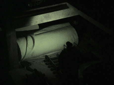
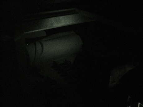 I had left the
rear headlight as the stock incandescent bulb because a narrow beam 5
mm LED would not easily fit due the geometry of the rear headlight
mounting. However, the beam that it case was pretty dismal. This is a
shot of the illumination to the rear on my test track in the garage
illuminating a roll of paper towels that is used as a bumper on the end
of the test track. I had to use the high sensitivity Night Shot mode of
my camera just to get a picture at all. The camera's IR illuminator is
turned off.
I had left the
rear headlight as the stock incandescent bulb because a narrow beam 5
mm LED would not easily fit due the geometry of the rear headlight
mounting. However, the beam that it case was pretty dismal. This is a
shot of the illumination to the rear on my test track in the garage
illuminating a roll of paper towels that is used as a bumper on the end
of the test track. I had to use the high sensitivity Night Shot mode of
my camera just to get a picture at all. The camera's IR illuminator is
turned off.
 The front headlight
conversion went so well that I elected to do the rear one too. However,
I used a 3 mm warm white LED because when the leads are bent
perpendicular to the body, it actually fits up inside the headlight
housing and the lead frame is a perfect fit for the existing
socket.
The front headlight
conversion went so well that I elected to do the rear one too. However,
I used a 3 mm warm white LED because when the leads are bent
perpendicular to the body, it actually fits up inside the headlight
housing and the lead frame is a perfect fit for the existing
socket.
I did have to change the current limiting resistor so I had to open
the tender and cut the old 390 ohm resistor out and add an 820 ohm one
back in. The socket is not polarized as the bulbs didn't need it, but
they way that I originally plugged the LED in was correct, 50/50
chance.
 This is the same
test configuration with the same camera with the same settings. The LED
draws half the current as the bulb but is MUCH brighter and because it
is a 60 degree illumination angle LED, it spreads light around pretty
well too, at least as well as the old bulb. It is now too bright in the
"dim" mode so I'll have to reprogram the decoder to tone it down.
This is the same
test configuration with the same camera with the same settings. The LED
draws half the current as the bulb but is MUCH brighter and because it
is a 60 degree illumination angle LED, it spreads light around pretty
well too, at least as well as the old bulb. It is now too bright in the
"dim" mode so I'll have to reprogram the decoder to tone it down.
This page has been accessed  times since 1 Nov 08.
© 2008-2009 George Schreyer
Created 1 Nov 08
Last Updated January 23, 2009