 This page deals with the second version of the Aristo 4-6-2
Pacific. Aristo had made and older
version for many years and I have one. The older engine, and the
heavyweight passenger cars that it pulled, were one of the driving forces
in the creation of the GIRR in the first place. However, the
older version has a weak drive train and it tends to lug down. I have
been tweaking on that engine for years to get it to pull harder, but it
just won't. This weakness was recognized and has been fixed through a
complete redesign of the drive train.
This page deals with the second version of the Aristo 4-6-2
Pacific. Aristo had made and older
version for many years and I have one. The older engine, and the
heavyweight passenger cars that it pulled, were one of the driving forces
in the creation of the GIRR in the first place. However, the
older version has a weak drive train and it tends to lug down. I have
been tweaking on that engine for years to get it to pull harder, but it
just won't. This weakness was recognized and has been fixed through a
complete redesign of the drive train.
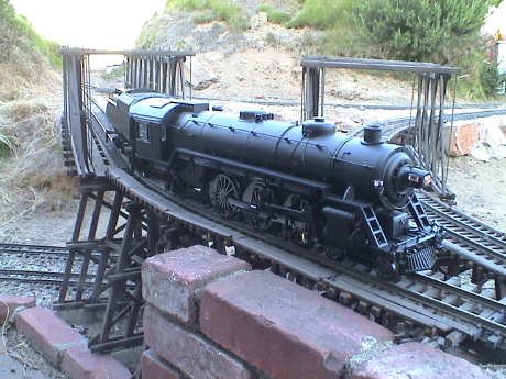
The Aristo Pacific is apparently modeled after the B&O President
Class. The model matches the size, overall appearance and some of the
detail locations of that class (pops, whistle and dynamo). Pacific's
were predominantly passenger engines, however they could be pressed
into freight service when necessary.
The model is nominally 1:29 scale and scales out pretty close. The
model has fair detail and runs very smoothly and quietly except for a
few nits.
The second version of the Pacific was delivered to the GIRR property on
Oct 20, 2008 but it may have been available since 2003.
The new Pacific and the Mikado are essentially the same loco with
changes in the gearbox and running gear. Much of the information
presented here may apply to the Mikado as well.
Contents
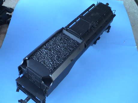 This Pacific is an
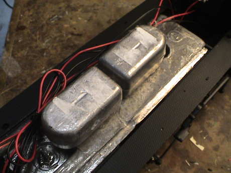
undecorated version that came with a Vanderbilt tender. The tender
itself is very long, 18" over the end sills vs 14.5" on the standard
tender. However, it is mostly empty. The coal load is removable
revealing a small PWB and a speaker near the front. The water tank
portion is empty except for a couple of small weights over the rear
truck.
This Pacific is an
undecorated version that came with a Vanderbilt tender. The tender
itself is very long, 18" over the end sills vs 14.5" on the standard
tender. However, it is mostly empty. The coal load is removable
revealing a small PWB and a speaker near the front. The water tank
portion is empty except for a couple of small weights over the rear
truck.
The tender picks up power, but only on two wheels of the rear truck.
I'll probably add pickups to two wheels of the front truck as well.
The drawbar on the tender is different from the old one. The
original drawbar had a twisted tab connection to the locomotive. This
was secure and would NEVER disconnect on it's own. However, it was a
real bear to connect and disconnect. The new version is a simple pin
and much easier to deal with. In the limited testing that I've done so
far, it has not disconnected by itself while pulling but it will
disconnect at times when pushing a very heavy load.
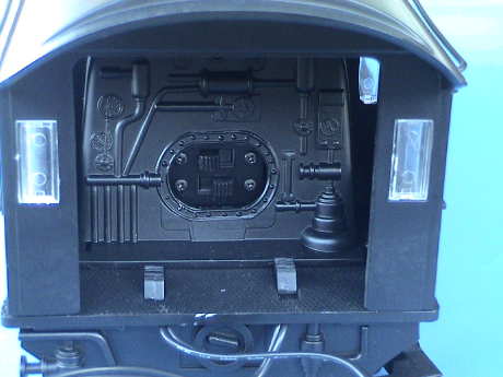 The cab has less detail
than the original Pacific. There is no firebox light. Instead, in the
firebox are the motor and track power switches. The ones on the floor
control the lights and smoke unit.
The cab has less detail
than the original Pacific. There is no firebox light. Instead, in the
firebox are the motor and track power switches. The ones on the floor
control the lights and smoke unit.
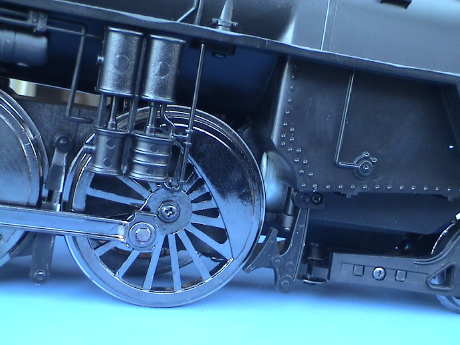
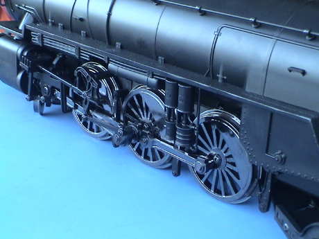 The running gear
externally looks much the same as the original Pacific but there are
significant differences. The wheels are a different material than the
copper based alloy of the old Pacific. The gearing is completely
different. The front axle is more or less fixed and rocks only slightly
on elastic pads within the gear block. The other two axles are allowed
to rock quite a bit to follow uneven track.
The running gear
externally looks much the same as the original Pacific but there are
significant differences. The wheels are a different material than the
copper based alloy of the old Pacific. The gearing is completely
different. The front axle is more or less fixed and rocks only slightly
on elastic pads within the gear block. The other two axles are allowed
to rock quite a bit to follow uneven track.
The connecting rods and valve gear are all metal on the new version
as opposed to plastic on the previous version. The holes in the rods
are slightly oversized so that the rods can slop a little. There
doesn't seem to be any rod bind on any rod at any wheel rotation.
The drivers do not appear to be keyed. They are mounted on a tapered
shaft per the recent Aristo practice. Therefore if a wheel slips, there
could be a serious rod bind which might result in broken parts or
stripped gears. Pay close attention to the running smoothness of this
loco. Any abrupt change is an indicator that the loco should be taken
out of service immediately for inspection.
Greg Elmassian has had some difficulty with the wheel attachment
method. See his
website for more details.
 The motor mount is very
different. This motor mounts coaxially to the drive shaft that runs
above the driven axles. All the driving axles are driven via individual
rocking gearboxes. The old Pacific mounted the motor at an angle and
used a universal joint to transfer torque to the drive shaft. This
universal joint was a weak point of the original design. The drive
shaft on the old Pacific drove the first and 3rd drivers, the center
driver was driven through the rods.
The motor mount is very
different. This motor mounts coaxially to the drive shaft that runs
above the driven axles. All the driving axles are driven via individual
rocking gearboxes. The old Pacific mounted the motor at an angle and
used a universal joint to transfer torque to the drive shaft. This
universal joint was a weak point of the original design. The drive
shaft on the old Pacific drove the first and 3rd drivers, the center
driver was driven through the rods.
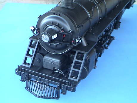 The front detail is
much the same as the original Pacific. An optional front coupler is
supplied, but the pilot must be removed to use it. There is a harness
at the front that carries track power. The headlight is
non-directional. The control box below the smoke box is now just a
visual detail. On the old Pacific, this box is where smoke fluid was
inserted.
The front detail is
much the same as the original Pacific. An optional front coupler is
supplied, but the pilot must be removed to use it. There is a harness
at the front that carries track power. The headlight is
non-directional. The control box below the smoke box is now just a
visual detail. On the old Pacific, this box is where smoke fluid was
inserted.
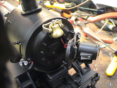
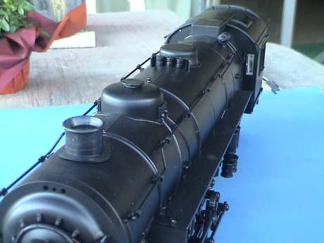 The boiler has the
same detail as the original Pacific. I noticed that there was no bell
or whistle either, although the holes to mount them were present.
The boiler has the
same detail as the original Pacific. I noticed that there was no bell
or whistle either, although the holes to mount them were present.
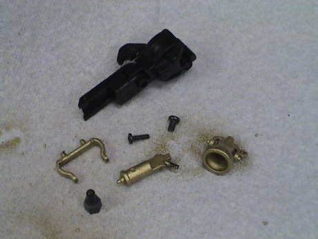 My unit was
undecorated, and so were the bell and whistle. I found them molded in
black plastic in a bag with the front coupler. I have painted them with
brass paint. There is a small metal object (lower left) that is
intended go somewhere, but I can't figure out what it is.
My unit was
undecorated, and so were the bell and whistle. I found them molded in
black plastic in a bag with the front coupler. I have painted them with
brass paint. There is a small metal object (lower left) that is
intended go somewhere, but I can't figure out what it is.
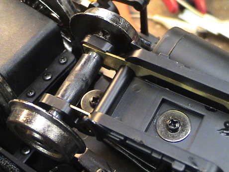 The pilot truck is
similar to the original Pacific truck, but it is not wired to pick up
power. This could easily be changed as the contacts are there.
The pilot truck is
similar to the original Pacific truck, but it is not wired to pick up
power. This could easily be changed as the contacts are there.
 I had a bit of a
problem with the smokebox door. I noticed that a wire was pinched in
the door. When I opened the door to free the wire, I found that the
door would not stay closed. The pinched wire was actually holding the
door closed. This wasn't at all good.
I had a bit of a
problem with the smokebox door. I noticed that a wire was pinched in
the door. When I opened the door to free the wire, I found that the
door would not stay closed. The pinched wire was actually holding the
door closed. This wasn't at all good.
Since there is no door latch, something has to hold it closed. There
are small ridges at the top, side and bottom of the door to allow it to
wedge closed. However, the hinge has been modified so that the door
cannot press into the smokebox front and engage these ridges. A small
screw has been added as a door stop to keep the door straight, but
there was not no way to keep the door closed.
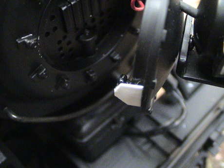 I glued a small
0.015" thick styrene ship to the side of the door. This piece is long
enough to reach back into the smokebox front and the door will wedge
shut.
I glued a small
0.015" thick styrene ship to the side of the door. This piece is long
enough to reach back into the smokebox front and the door will wedge
shut.
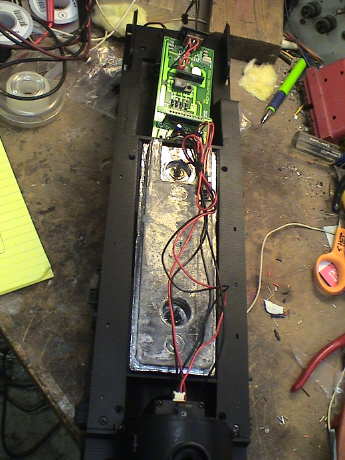 With the boiler
removed (4 screws under the cab, 4 under the boiler and a 5th screw on
top at the junction of the boiler and smokebox), the inside is revealed
to have some serious internal volume available for weight or batteries.
The PWB for the loco is mounted back in the firebox. From there forward
to the smokebox, the boiler is clear.
With the boiler
removed (4 screws under the cab, 4 under the boiler and a 5th screw on
top at the junction of the boiler and smokebox), the inside is revealed
to have some serious internal volume available for weight or batteries.
The PWB for the loco is mounted back in the firebox. From there forward
to the smokebox, the boiler is clear.
The PWB can be freed by removing the backhead (two screws
underneath) and the rear sill (one screw) to free up the wires leading
to the tender. Then the circuit board will lift after the removal of
four screws.
Differences Between the New and Old
Pacific
The new Pacific is an upgrade from the older version that dated from
the early 90's. There are quite a few differences, some major and some
minor. Some differences could be considered to be worse than on the
original design.
-
Major Differences
-
Missing U-Joint. The biggest difference is the removal of the
U-joint between the motor and the drive shaft. The loco was, and to
some extent, still is, undermotored and the U-Joint in the older
version was just too much. U-Joints run off axis add serious motor
loads which this loco can ill afford.
-
Motor Fan. The older Pacific was undermotored so that the
motor tended to overheat. The new one is still undermotored, but at
least the motor fan helps keep the motor from melting out of the bottom
of the loco.
-
Driver Material. The older Pacific used some sort of bronze
casting alloy for all of the wheels. These tended to oxidize readily.
The new Pacific uses a different material that appears to resist
oxidation much better.
-
Minor Differences
-
Gearing. Aristo makes a big deal of the new gearbox designs
in the new Pacific. These are an improvement, mostly in logistics and
probably reliability, but the old gearing wasn't bad. The gear ratio of
both versions is similar, neither has gearing that is too "tall" as the
top speeds of both are reasonable.
-
Modular Gearboxes. All the driven axles in the new Pacific
are driven via gears. The method used is a good one and works well, but
it is not clear that this actually results in a performance
improvement. Many electric model locos, some of them are very high
quality, use the siderods to power some of the drivers. It is not clear
that 100% gear drive is a significant improvement.
-
Metal Drive Rods. The newer one has metal connecting and
drive rods. These look better and are probably stronger, but it is not
clear to me that they are a performance improvement.
-
Drawbar. The drawbar on the older Pacific was a major pain to
connect and disconnect but it never disconnected by itself. The newer
one is easier to deal with but does tend to disconnect in some backing
moves.
-
Flywheels. The newer Pacific incorporates two brass flywheels
into the gearbox assembly. These cannot hurt, but they do not appear to
be big enough to really have an impact.
-
Smoke Unit. The newer Pacific uses an electronic smoke unit.
It smokes well and ejects a strong smoke stream, but it does not chuff
in time with the drivers nor does it issue smoke from near the
cylinders. The newer one is protected from running dry.
-
DCC Socket. The older Pacific was not difficult to convert to
DCC because the wiring was easy to interpret and access. The newer one
has a PWB inside which accepts a "plug-n-play" DCC decoder or RC RX.
This is good for easy installs, but the board has some wiring issues
where things do not work quite "right." The headlight is
non-directional and the "track/battery" switch does not work right
(easily fixed). For those that don't want to install a compatible
decoder or receiver, the board actually gets in the way.
-
Constant Intensity Lighting. The newer Pacific has a low
voltage constant intensity lighting circuit. It provides better
lighting than the old one on DC track power, and is a little better yet
with PWC on the track. However, ALL the lights run from this circuit so
that the headlight does not reverse or dim.
-
Sound. The new Pacific does not come with sound. The original Pacific came with a marginal analog sound system, at least it was there already. The optional PH
Hobbies system in the older Pacific was not the best one available, but
it was competent.
-
Tender Power Pickup. The old Pacific's tender did not
contribute to power pickup. The newer one does but only on one truck.
Further, there were some problems with wiring differences between the
Vanderbilt and standard tender.
-
Firebox. The old Pacific had a firebox light. This could be
run from a random flicker function of a DCC decoder. The newer one has
switches in the firebox door and no light.
-
Battery Wiring. The newer Pacific has a wiring bus and
connectors at both ends to make a battery installation in the tender
easier. This is somewhat complicated by the wiring "error" in the
"track/battery" switch.
-
Steps Backward?
-
Driver Attachment. The older Pacific used screws to attach
the drivers to a keyed axle. This prevented the wheels from drifting
"out of quarter" as long as the screws remained in place, which they
often did not. The newer Pacific uses tapered axles which can allow a
driver to shift on the axle causing the side rods to bind. Side rod
breakage has been reported as a result of this design.
 There are two harnesses
between the loco and tender. One pair is to bring track or battery
power forward to the loco. The wires leading to the rear truck have
polyfuse type devices in series with them. Since track power and
battery power are brought forward on the same pair, if battery power is
desired, then the wires to the rear truck must be cut. The loco has a
switch to disconnect the power pickups, the tender does not. However,
note that the pickup disconnect switch is MISWIRED. It needs some
simple changes, see below.
There are two harnesses
between the loco and tender. One pair is to bring track or battery
power forward to the loco. The wires leading to the rear truck have
polyfuse type devices in series with them. Since track power and
battery power are brought forward on the same pair, if battery power is
desired, then the wires to the rear truck must be cut. The loco has a
switch to disconnect the power pickups, the tender does not. However,
note that the pickup disconnect switch is MISWIRED. It needs some
simple changes, see below.
The other pair is wired to the rear headlight, it also provides
power to the the sound system power connector. This is a little
confusing to me because if the rear headlight is properly controlled
via DCC, then the sound power will be cut off when running forward.
This mystery was solved later when I determined that NONE of the lights
are "properly" wired for DCC.
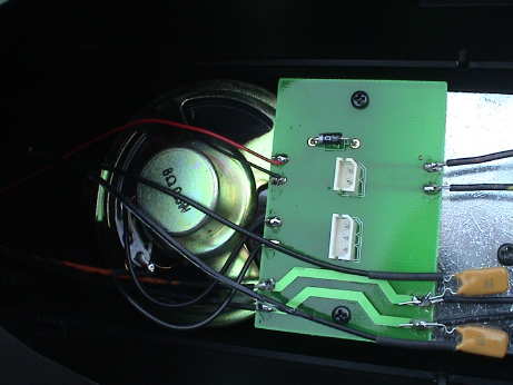
 There is a PWB mounted
to the back of the motor which brings track power out of the motor
block and sends motor power in to the motor.
There is a PWB mounted
to the back of the motor which brings track power out of the motor
block and sends motor power in to the motor.
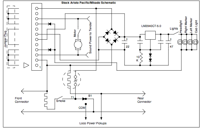
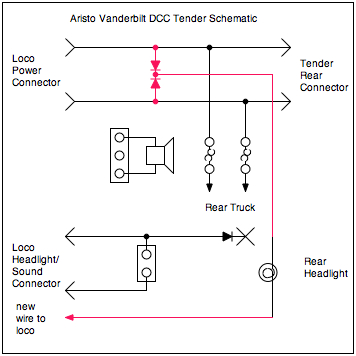
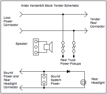 This is a schematic of
the tender in it's stock form. Power is bussed through the tender from
front to back. The connectors at the back are intended to be used for a
battery car but I use them to share track power down the length of a
train. The one tender truck is also connected to this bus through some
polyswitches for short circuit protection. The rear headlight and the
sound system power connector run from the motor circuit so that the
diode allows the rear headlight to be directional. The connector would
be used to provide power to a conventional large scale sound system
such as a Soundtraxx Sierra or a Phoenix 2K2. I have more to say about
the speaker in the section on sound below.
This is a schematic of
the tender in it's stock form. Power is bussed through the tender from
front to back. The connectors at the back are intended to be used for a
battery car but I use them to share track power down the length of a
train. The one tender truck is also connected to this bus through some
polyswitches for short circuit protection. The rear headlight and the
sound system power connector run from the motor circuit so that the
diode allows the rear headlight to be directional. The connector would
be used to provide power to a conventional large scale sound system
such as a Soundtraxx Sierra or a Phoenix 2K2. I have more to say about
the speaker in the section on sound below.
If you use a battery power no matter where the batteries are
mounted, then you should CUT the wires leading to the tender pickups to
prevent power from being backfed to the track OR don't connect the
harness on the engineer's side to the tender if you have installed
batteries directly into the loco.
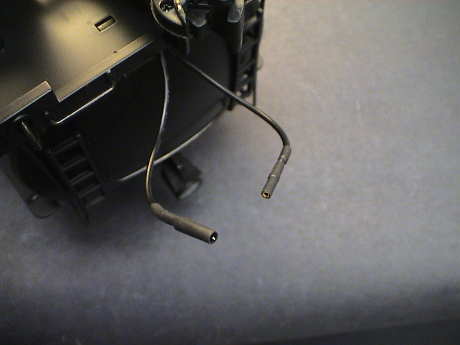 I did cut
off the power connector at the rear of the tender and put on my
standard contacts instead.
I did cut
off the power connector at the rear of the tender and put on my
standard contacts instead.
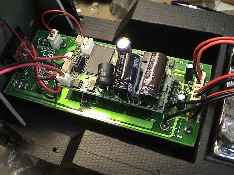
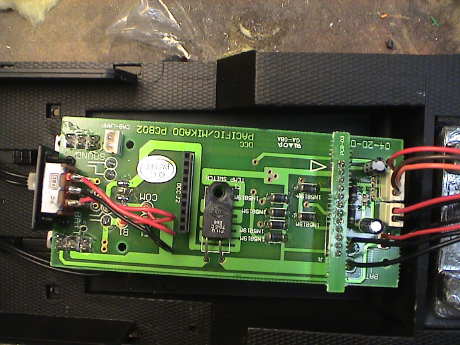 The PWB in the loco
contains the DCC socket, the four switches for controlling the motor,
lights, smoke and power pickups, a thermal switch and a 5 volt
regulator. The thermal switch senses the temperature of a meander line
printed on the PWB. This line carries current from the power pickups
and the rear connector to the DCC decoder socket and then on to the
motor. If there is too much average current in the strip, it will heat
and trip the thermal switch and cut power to the loco.
The PWB in the loco
contains the DCC socket, the four switches for controlling the motor,
lights, smoke and power pickups, a thermal switch and a 5 volt
regulator. The thermal switch senses the temperature of a meander line
printed on the PWB. This line carries current from the power pickups
and the rear connector to the DCC decoder socket and then on to the
motor. If there is too much average current in the strip, it will heat
and trip the thermal switch and cut power to the loco.
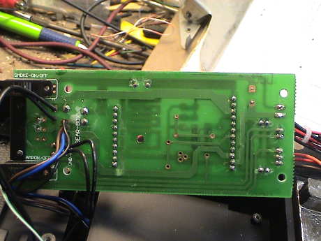 This is the
backside of the main board. It a simple two layer board and between the
two photos, much of the wiring detail can be worked out.
This is the
backside of the main board. It a simple two layer board and between the
two photos, much of the wiring detail can be worked out.
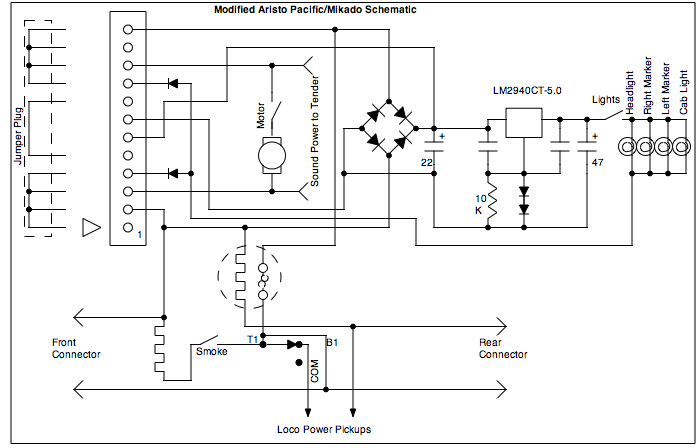
 When I went
to draw this schematic of the Pacific as delivered, something didn't
make any sense. I rechecked and I believe that there is either a design
or manufacturing error in the wiring of the Battery/Track switch.
First, the way that it is wired, the switch works backwards from the
manual. Second, when the switch is in the "track" position, the battery
lead from the tender is disconnected. This also disconnects the power
pickups in the tender. This should NEVER happen. The "battery" wiring
going to the front and rear connectors SHOULD NEVER be disconnected.
Also, the power leading to the loco via the front connector bypasses
the thermal cutout heater circuit.
When I went
to draw this schematic of the Pacific as delivered, something didn't
make any sense. I rechecked and I believe that there is either a design
or manufacturing error in the wiring of the Battery/Track switch.
First, the way that it is wired, the switch works backwards from the
manual. Second, when the switch is in the "track" position, the battery
lead from the tender is disconnected. This also disconnects the power
pickups in the tender. This should NEVER happen. The "battery" wiring
going to the front and rear connectors SHOULD NEVER be disconnected.
Also, the power leading to the loco via the front connector bypasses
the thermal cutout heater circuit.
Otherwise the circuit is pretty straight forward. All the lighting
runs from a 5 volt low overhead regulator IC that has been fudged to
6.2 volts via the addition of two diodes in the ground lead. The
lighting is controlled in an odd way by a DCC decoder installed in the
DCC socket. If either F0f or F0r is on, the lights are grounded and all the
lights come on.
The sound power heading to the tender is not switched so that, if a
conventional track powered sound system like a Sierra or 2K2 is used,
the loco can sit on powered track and allow the sound system to charge.
The rear headlight runs from this circuit also so that it is
directional via a diode in the tender.
 I
rewired the switch by moving two wires on the switch. Now, the battery
bus is always active AND the position of the switch matches the manual.
The labels "B1", "T1" and "COM" are the labels on the PWB for the three
wires leading to this switch. Since I don't intend to use the front
power connector, I left it alone.
I
rewired the switch by moving two wires on the switch. Now, the battery
bus is always active AND the position of the switch matches the manual.
The labels "B1", "T1" and "COM" are the labels on the PWB for the three
wires leading to this switch. Since I don't intend to use the front
power connector, I left it alone.
This problem gave me quite a bit of trouble during the DCC install
(described below) as the loco was getting power from only 2 wheels in
the tender as I had flipped the switch to the "Track" side which was
really the "Battery" side.
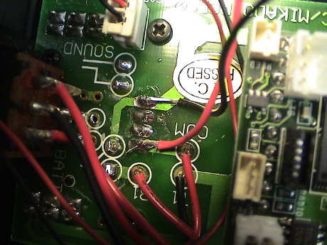
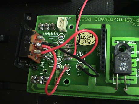 This is a photo of
the rewired switch. Since others have reported the same kind of
problems, the wiring of my particular loco may not be unique.
Basically, on the top row of contacts on the top switch behind the
firebox, move the wire on the engineer's side to the center contact
along with the wire that is already there. Then move the wire on the
fireman's side to the engineer's side. Then the switch will work as
shown in the manual AND the tender wheels will contribute to power
pickup.
This is a photo of
the rewired switch. Since others have reported the same kind of
problems, the wiring of my particular loco may not be unique.
Basically, on the top row of contacts on the top switch behind the
firebox, move the wire on the engineer's side to the center contact
along with the wire that is already there. Then move the wire on the
fireman's side to the engineer's side. Then the switch will work as
shown in the manual AND the tender wheels will contribute to power
pickup.
The smoke unit has been changed out too. It is now one of the Aristo
self contained fan driven units that is described on my SD45 Tips page. The unit operates from
track power via a switch in the cab. Unlike the older Pacific, smoke is
NOT ejected from the cylinder assembly nor does it puff.
 I had some problems with the new smoke unit, it not only wants a big fluid load, 1 mL or greater, it also does not like high track voltages, above 20 volts or so. If either condition occurs, it'll shut down after about 2 minutes. I put about 15 ohms in series with the one in the Pacific and it behaved much better.
The smoke unit can be easily accessed. Loosen two screws at the sides of the smokebox cover and pull off the cover. Pull out the smoke stack and then you can just pull the smoke unit out of the front. The wires should pull out far enough for you to disconnect the smoke unit. It goes back in the same way, but be sure that the tabs on the sides of the smoke unit fit into the slots inside the smokebox.
The loco runs pretty well. It does not lug as much as the original
Pacific although I do detect some lugging at the highest loads, just
before the loco slips. On my layout, with a load of 5 heavyweights, the
loco lugs and then slips at one spot where the load is the highest due
to the fact that the whole train is on a 1.6% grade AND much of the
train is on 180° worth of 8' diameter curved track. I draped a
baggie with a pound of lead over the boiler and the slipping went away
so I'll probably install that weight inside the loco when I have it
open.
The Pacific pulls about the same load (12 freight cars on my worst
grade) as the original one before the wheels slip and draws a little
more current, 2.5 amps at full slip. The stall current is about the
same as the old loco, less than 5 amps. I didn't measure the current
running light on the old one, but the new one draws about 1 amp.
However, after extended running at all the load it can handle, the
motor doesn't get smoking hot like the old one. The air temperature
during the test was about 60°F and the motor case temperature
stabilized at about 80°F. On the old one, the temperature of the
motor would climb to dangerous levels in about a half hour of running
and I'd have to give it a rest as it was obviously losing torque.
The loco tracks steadily and didn't show any obvious tendency to
derail. Power pickup is consistent and reasonably stable, even on
obviously dirty track even with only 8 wheels collecting power between
the loco and tender. I have added power pickup to two wheels on the
tender and four on the loco just for redundancy.
 I did notice the
tendency for the loco to slip under certain loads that I wanted it to
handle better so I added some weight. One pound would have been enough,
but I added two. This can be dangerous as wheel slippage is a load
limiter that prevents the motor load from getting too high, but
temperature measurements on the loco loaded up show that the fan is
doing a good job of cooling the motor and it doesn't heat much even
with the weight added.
I did notice the
tendency for the loco to slip under certain loads that I wanted it to
handle better so I added some weight. One pound would have been enough,
but I added two. This can be dangerous as wheel slippage is a load
limiter that prevents the motor load from getting too high, but
temperature measurements on the loco loaded up show that the fan is
doing a good job of cooling the motor and it doesn't heat much even
with the weight added.
Even with 2 lbs added, the loco tended to slip some at the worst
spots so I added yet another pound of lead in the form of smaller
pieces. This allowed the loco to barely retain traction.
 My Pacific has a
tendency to flop from side to side occasionally by up to 3° each
way. None of the driver sets are firmly prevented from rocking as I
would have expected. I took the brick cover off to look around, and the
plastic pads that are used on some other Aristo locos to prevent one
axle from rocking are not in evidence here. I am going to do a little
research to determine if this is a generic issue or just a peculiarity
of this one loco. One of the axles should be constrained to keep the
body from rocking.
My Pacific has a
tendency to flop from side to side occasionally by up to 3° each
way. None of the driver sets are firmly prevented from rocking as I
would have expected. I took the brick cover off to look around, and the
plastic pads that are used on some other Aristo locos to prevent one
axle from rocking are not in evidence here. I am going to do a little
research to determine if this is a generic issue or just a peculiarity
of this one loco. One of the axles should be constrained to keep the
body from rocking.
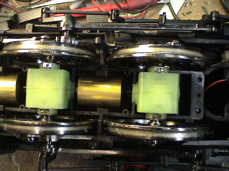
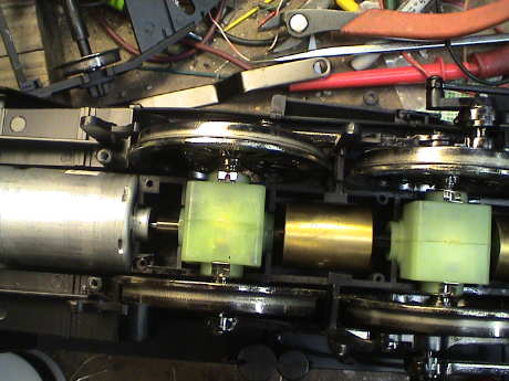 The single large motor
at the rear drives the individual gearboxes via a jointed shaft. The
shafts between the gearboxes have a small brass flywheel integrated
within them. The gearboxes themselves are similar to the ones in the SD45.
The single large motor
at the rear drives the individual gearboxes via a jointed shaft. The
shafts between the gearboxes have a small brass flywheel integrated
within them. The gearboxes themselves are similar to the ones in the SD45.
All is not well though. The running gear makes a variety of squeaks
at the rate of one squeak of each type per driver revolution. The
squeaks appear to originate at the connecting rods. If I press on a rod
while the engine is running, I can feel a vibration related to the
squeak in the rods. Each rod to wheel connection seems to make it's own
squeak at various times. Lubricating the rods didn't seem to help
much.
After an hour or so of running, I noticed that the paint was being
rubbed off the brake shoe assemblies. I applied a little oil to the
worn surface of each shoe and the squeak vanished.
I assume that with sufficient running, the plastic brake shoes will
wear enough by themselves so that the squeak would stop. With the oil
on there, that wear will be substantially reduced, but at least it
doesn't squeak in the meantime.
 I
added power pickup to the front truck of the tender by soldering wires
to the wheel bushing on one side. I pulled the bushings out of the
tender truck frame to do this, I didn't want to melt the truck.
I
added power pickup to the front truck of the tender by soldering wires
to the wheel bushing on one side. I pulled the bushings out of the
tender truck frame to do this, I didn't want to melt the truck.
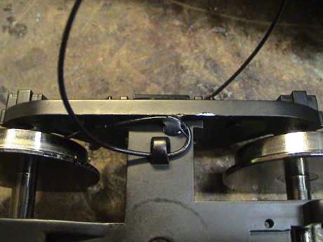 The wires
are routed across the top of the truck the same way that Aristo did the
rear truck.
The wires
are routed across the top of the truck the same way that Aristo did the
rear truck.
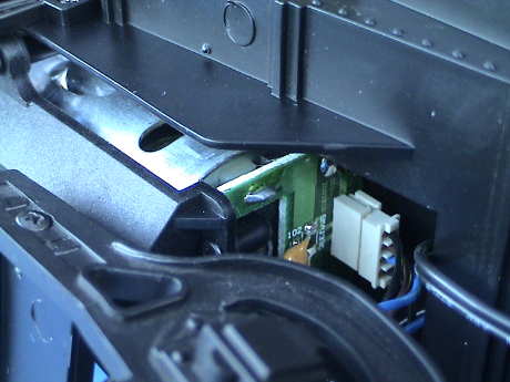
 The
connection point inside the tender is at the polyswitches. The black
wires leading back into the tender go to the rear truck.
The
connection point inside the tender is at the polyswitches. The black
wires leading back into the tender go to the rear truck.
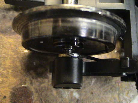
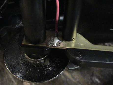 The leading
truck on the loco can also pick up power but Aristo chose not to wire
it. I soldered a wire to the brass strap inside the truck on each side
and then routed the wire back up through a large hole into the
loco.
The leading
truck on the loco can also pick up power but Aristo chose not to wire
it. I soldered a wire to the brass strap inside the truck on each side
and then routed the wire back up through a large hole into the
loco.
 The other
end of the wires are attached to the top of the PWB where the power
pickups from the gearbox go. Note that the pad on the left side of the
loco services the right side wheels.
The other
end of the wires are attached to the top of the PWB where the power
pickups from the gearbox go. Note that the pad on the left side of the
loco services the right side wheels.
Installing Kadee Couplers
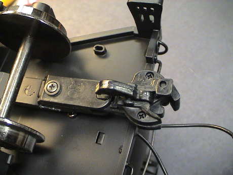 The rear
of the tender has a standard Aristo knuckle coupler. These work pretty
well when used with other Aristo couplers but they don't work so well
with Kadee couplers. While I was doing the tractive effort tests I had
to tie wrap the couplers together to get the test data.
The rear
of the tender has a standard Aristo knuckle coupler. These work pretty
well when used with other Aristo couplers but they don't work so well
with Kadee couplers. While I was doing the tractive effort tests I had
to tie wrap the couplers together to get the test data.
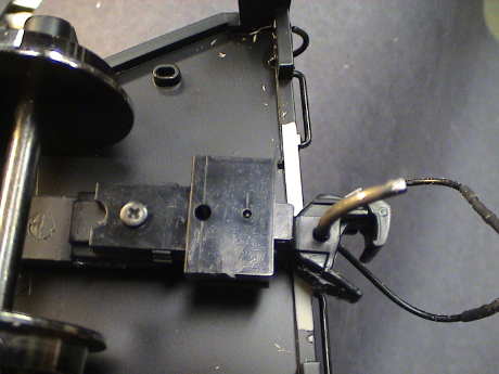 A Kadee 831 goes
on quite easily. Mount the connector on the outer hole on the tang. The
coupler will slightly interfere with the rear sill of the tender so I
ground off a little of the sill to provide some real clearance. The
coupler comes out at exactly the right height.
A Kadee 831 goes
on quite easily. Mount the connector on the outer hole on the tang. The
coupler will slightly interfere with the rear sill of the tender so I
ground off a little of the sill to provide some real clearance. The
coupler comes out at exactly the right height.
The new Pacific is a piece of cake to convert to DCC with a plug and
play style decoder such as QSI sound decoder or a Digitrax DG583AR.
After watching how much current the loco can pull, a smaller DG383AR
might handle it, but the larger one is probably a better bet.
 I used a QSI decoder
to take advantage of the excellent sound that this decoder provides as
well.
I used a QSI decoder
to take advantage of the excellent sound that this decoder provides as
well.
The headlights are an issue. Aristo choose to wire them such that
the plug and play decoder activates ALL of the lighting at once, but it
cannot control the directionality. The headlights, markers and cab
light all run from the same circuit and are on all the time that F0f or
F0r is enabled. The QSI nominally dims the headlights when the loco is
standing. In effect, this turns off all the lights when the loco stops.
With a different kind of decoder, the lights would be on all the time.
The rear headlight on the tender runs via a diode from the motor
circuit so that it is directional but it is on only when the motor
power is available.
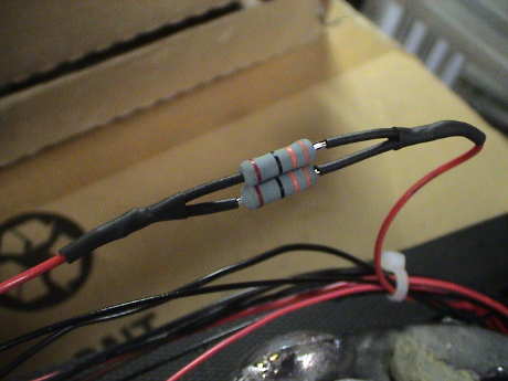
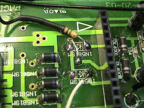 Modifying the
Pacific to provide legitimate front headlight control is fairly easy.
All the work is in the harnesses and the top side of the PWB. No cuts
are required but two surface mounted diodes, now missing in this photo
but marked with silkscreen, need to be removed. This frees up the
headlight function pins on the decoder. A jumper, as seen in the photo,
then permanently grounds the other lights and turns them on. The resistor in
the photo is for current limiting of the LED I installed to replace the
stock headlight, it is 150 ohms. It is soldered to the pad that
connects to the front headlight pin of the decoder. The white wire is
connected to the reverse headlight and runs off to the tender.
Modifying the
Pacific to provide legitimate front headlight control is fairly easy.
All the work is in the harnesses and the top side of the PWB. No cuts
are required but two surface mounted diodes, now missing in this photo
but marked with silkscreen, need to be removed. This frees up the
headlight function pins on the decoder. A jumper, as seen in the photo,
then permanently grounds the other lights and turns them on. The resistor in
the photo is for current limiting of the LED I installed to replace the
stock headlight, it is 150 ohms. It is soldered to the pad that
connects to the front headlight pin of the decoder. The white wire is
connected to the reverse headlight and runs off to the tender.
The headlight itself is broken out of the light harness inside the
smokebox and the black wire brought back to one of the pads vacated by
the diodes. The two decoder pads are the ones nearest the DCC
connector. There is a 50% chance of getting it wrong the first time,
but if the headlight comes on in the wrong direction, switch to the
other pad.
 All the stock
lighting power is brought forward to the smokebox via a red and black
wire pair. This pair terminates on a little distribution board inside
the smokebox. The smokebox cover is easily removed by loosening, not
removing, one screw on each side of the smokebox front cover. The
headlight and markers are wired in parallel. The black wire that leads
to the headlight is lifted and routed back to the PWB on a new wire. If
the stock headlight 6 volt bulb is retained, then this wire will
connect directly to a pad vacated by one of the two surface mounted
diodes that were removed.
All the stock
lighting power is brought forward to the smokebox via a red and black
wire pair. This pair terminates on a little distribution board inside
the smokebox. The smokebox cover is easily removed by loosening, not
removing, one screw on each side of the smokebox front cover. The
headlight and markers are wired in parallel. The black wire that leads
to the headlight is lifted and routed back to the PWB on a new wire. If
the stock headlight 6 volt bulb is retained, then this wire will
connect directly to a pad vacated by one of the two surface mounted
diodes that were removed.
 The stock headlight
can be accessed by removing the headlight housing from it's bracket by
removing one screw underneath the headlight housing. I managed to push
the headlight lens out of the housing by pushing on the headlight
wires. The lens is held in with adhesive but mine yielded easily. If
yours is attached more securely, you might have to squeeze the assembly
gently to try to break the bond.
The stock headlight
can be accessed by removing the headlight housing from it's bracket by
removing one screw underneath the headlight housing. I managed to push
the headlight lens out of the housing by pushing on the headlight
wires. The lens is held in with adhesive but mine yielded easily. If
yours is attached more securely, you might have to squeeze the assembly
gently to try to break the bond.
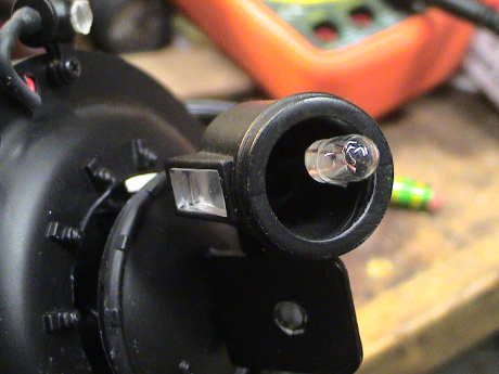
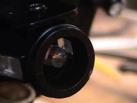 A 5 mm white
LED fits in the lens perfectly. This view is just before I pushed the
lens back in. Simply cut the wires from the bulb as close as you can
get and clean up the ends. Then attach the red wire to the LED positive
terminal. This one is easy to identify because it is usually the
smaller of the two electrodes as seen through the side of the LED
housing. The black wire solders to the other terminal. Insulate the
joints with short pieces of shrink tube and push the whole works back
together. My lens stuck in place so I didn't have to rebond it.
A 5 mm white
LED fits in the lens perfectly. This view is just before I pushed the
lens back in. Simply cut the wires from the bulb as close as you can
get and clean up the ends. Then attach the red wire to the LED positive
terminal. This one is easy to identify because it is usually the
smaller of the two electrodes as seen through the side of the LED
housing. The black wire solders to the other terminal. Insulate the
joints with short pieces of shrink tube and push the whole works back
together. My lens stuck in place so I didn't have to rebond it.
 I brought one lead
of the rear headlight forward to the decoder and soldered to the one of
the pads vacated by the diodes as shown in an earlier photo. The other
rear headlight lead is connected to a synthetic "blue wire" in the
tender. The blue wire is synthesized by a couple of diodes as shown in
the diagram.
I brought one lead
of the rear headlight forward to the decoder and soldered to the one of
the pads vacated by the diodes as shown in an earlier photo. The other
rear headlight lead is connected to a synthetic "blue wire" in the
tender. The blue wire is synthesized by a couple of diodes as shown in
the diagram.
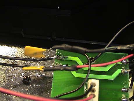
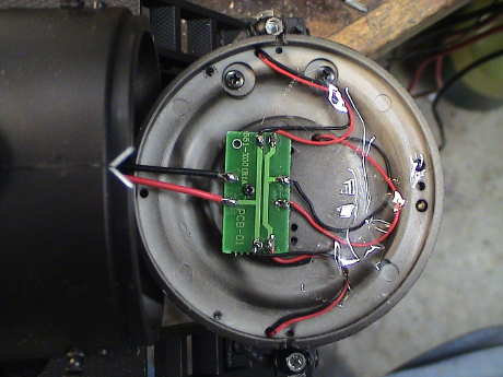
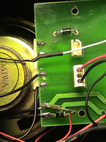 This wiring is
shown in this photo. The red and black wires that used to be connected
to the pads in the upper left are now connected to the diode pair
(lower left) that makes + common for the light. The black wire is
connected to the rear headlight function of the decoder. I already had
a spare wire in my speaker harness so this was the easiest approach for
my situation. I left the stock incandescent 18 volt bulb in place.
This wiring is
shown in this photo. The red and black wires that used to be connected
to the pads in the upper left are now connected to the diode pair
(lower left) that makes + common for the light. The black wire is
connected to the rear headlight function of the decoder. I already had
a spare wire in my speaker harness so this was the easiest approach for
my situation. I left the stock incandescent 18 volt bulb in place.
Alternately, if the sound power connector in the tender is NOT being
used, then the "sound power" wires that already exist can be reassigned
into "rear headlight" wires. Then these two wires that lead to the loco
PWB (labeled "sound" on the PWB) would be lifted from the pads that
they are soldered to and reconnected between the "+" terminal of the
on-board bridge rectifier and the other function pad on the PWB (where
the diodes were removed). Polarity matters here unless you short out
the diode in the tender.
There is a 2.5" round speaker in the tender, but it looks pretty
wimpy. It is rated at only 0.5 watts and has a completely plastic cone.
The QSI sound system will produce up to 5 watts and could easily burn
this speaker up so it will get a better one before long. The only
connection for the speaker is in the tender. There is a power socket
and a speaker socket. However, the QSI sound decoder mounts in the loco
so I'll add a new wire set to provide a connection to the speaker in
the tender.
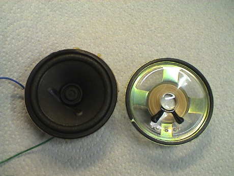 These are two 2.5"
round speakers. The one that comes in the Pacific is the one on the
right with the clear plastic cone. The one on the left is a speaker
that I recovered from a defunct clock radio/CD player. This one has a
more conventional paper cone but the cone mounting is much softer and
the cone has much better movement capability. This is an indicator that
the paper cone speaker will have a lower resonant frequency and better
bass response.
These are two 2.5"
round speakers. The one that comes in the Pacific is the one on the
right with the clear plastic cone. The one on the left is a speaker
that I recovered from a defunct clock radio/CD player. This one has a
more conventional paper cone but the cone mounting is much softer and
the cone has much better movement capability. This is an indicator that
the paper cone speaker will have a lower resonant frequency and better
bass response.
Comparison testing of both speakers actually mounted in the tender
produced results that are pretty clear. The paper cone speaker works
much better, especially at the low end.
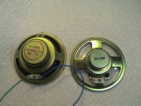 The old clock radio
speaker also has a larger magnet. It is rated at 1 watt, still a little
light for the QSI at max volume, but I usually turn the things down
quite a bit anyway.
The old clock radio
speaker also has a larger magnet. It is rated at 1 watt, still a little
light for the QSI at max volume, but I usually turn the things down
quite a bit anyway.
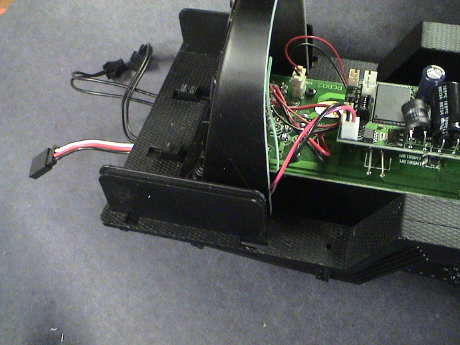 I
added a 3 conductor cable between the engine and the tender. I buy
these things at a local swap meet so I cannot provide a part number,
but they have heavy flexible wire and a mating connector on each end.
Therefore, when I cut them in the middle, I can use the two halves to
make a good loco/tender connection. The extra wire is currently unused.
I might eventually use it for a legitimate rear headlight control from
the DCC decoder. I also cut the jumper provided by QSI in the middle. I
spliced the 2 pin end to the end of my jumper cable and plugged it into
the QSI speaker socket.
I
added a 3 conductor cable between the engine and the tender. I buy
these things at a local swap meet so I cannot provide a part number,
but they have heavy flexible wire and a mating connector on each end.
Therefore, when I cut them in the middle, I can use the two halves to
make a good loco/tender connection. The extra wire is currently unused.
I might eventually use it for a legitimate rear headlight control from
the DCC decoder. I also cut the jumper provided by QSI in the middle. I
spliced the 2 pin end to the end of my jumper cable and plugged it into
the QSI speaker socket.
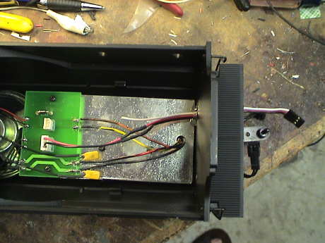 The
other end of the wire is connected to the 3 pin end of the QSI speaker
jumper and then plugged into the speaker socket on the PWB in the
tender.
The
other end of the wire is connected to the 3 pin end of the QSI speaker
jumper and then plugged into the speaker socket on the PWB in the
tender.
This photo was taken before I swapped out the speakers. The new
speaker is taller than the old one and the PWB will not mount back on
it's original posts. Instead, I attached it to the edge of the new
speaker with foam mounting tape.
Overall, the new Pacific and it's DCC and sound conversion was a
success. The new engine runs stronger than the old and it sounds pretty
good. A comparison of the two can be seen in this 6 minute movie. Note the pronounced
squeak in the new Pacific that went away (due to some lubrication) in
the post-DCC tests (the images without the shell).
This page has been accessed  times since 20 Oct 08.
© 2008-2010 George Schreyer
Created 20 Oct 08
Last Updated March 8, 2010
 15 Dec 08
 19 Nov 08