 25 Sep 08 25 Sep 08 14 May 09
[ Home ] [ Up ] [ Previous Page ] [ Next Page ]
25 Sep 08 25 Sep 08 14 May 09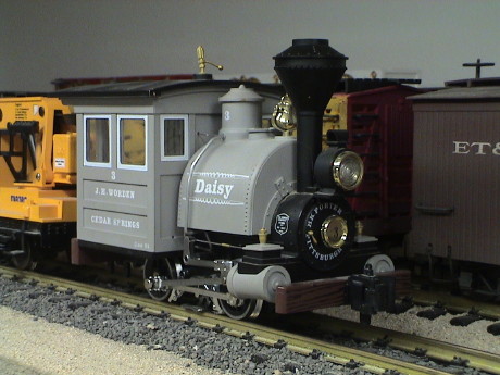 The
Lehmann Porter is a model of an 8 or 10 ton 0-4-0 steam locomotive
manufactured by the H.K. Porter company. This loco, and many like it,
came in a staggering array of configurations built to meet the needs of
industrial, mining and logging companies.
The
Lehmann Porter is a model of an 8 or 10 ton 0-4-0 steam locomotive
manufactured by the H.K. Porter company. This loco, and many like it,
came in a staggering array of configurations built to meet the needs of
industrial, mining and logging companies.
This loco is branded Lehmann, the parent company of LGB. The Lehmann brand was used on locos that were partially or fully manufactured outside of Germany or used substantial non-German parts. It appears that the motor in this unit may be a Mabuchi part. These locos were offered at lower prices than the LGB brand but typically ran just as well.
 The
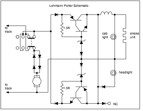
Porter is a pretty simple loco, but it does have a moderately
complicated electronic heart. All the electronics are on a PWB inside
the boiler. There are two 5 volt regulators, one operates in when the
loco is running in one direction and the other operate when the loco is
running in the other direction. It appears that the -5 volt regulator
is the one running forward based on the polarity of the headlight
diode. The headlight, cab light and smoke unit are all 5 volts. The two
jacks on the backhead are also 5 volts, NOT track power as is common
for LGB locos.
The
Porter is a pretty simple loco, but it does have a moderately
complicated electronic heart. All the electronics are on a PWB inside
the boiler. There are two 5 volt regulators, one operates in when the
loco is running in one direction and the other operate when the loco is
running in the other direction. It appears that the -5 volt regulator
is the one running forward based on the polarity of the headlight
diode. The headlight, cab light and smoke unit are all 5 volts. The two
jacks on the backhead are also 5 volts, NOT track power as is common
for LGB locos.
The switch on the backhead has three positions, off, lights only, lights and motor. The smoke unit is on whenever the lights are.
The motor has two standoff diodes for each polarity in series to create a condition where the lighting power gets a chance to come up to speed before the loco will start to move.
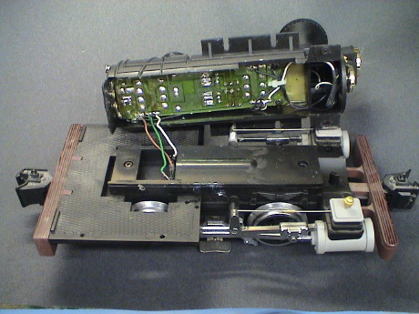
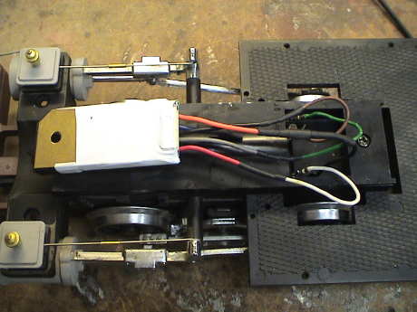
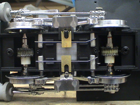 Getting to
the bottom of the Porter to lubricate the gearing is pretty easy, only
4 screws on the bottom cover need to be removed to get this far, but
this is about as far as one gets working from the bottom. The contact
arrangement is very similar to the LGB 2060 and the LGB Powered Tender.
Getting to
the bottom of the Porter to lubricate the gearing is pretty easy, only
4 screws on the bottom cover need to be removed to get this far, but
this is about as far as one gets working from the bottom. The contact
arrangement is very similar to the LGB 2060 and the LGB Powered Tender.
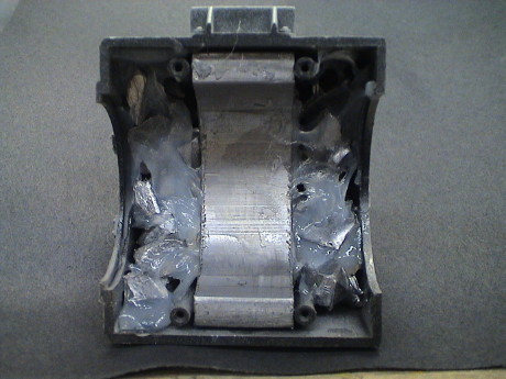 I had been into this
loco before but I don't remember doing it. There is a lead weight in
the saddle tank, I filled the rest of the tank with more lead held in
with silicone sealer.
I had been into this
loco before but I don't remember doing it. There is a lead weight in
the saddle tank, I filled the rest of the tank with more lead held in
with silicone sealer.
There are 4 screws under the saddle tank that must be removed to remove the tank. A handrail on the fireman's side must also be removed to release a wire that simulates a pipe. Then the saddle tank can be rolled off to the side although it is easier to get if off with the cab removed.
The cab is held on with 6 screws. it comes off easily. The cab light simply pulls out of the capture feature in the roof and dangles by it's wires.
This loco is common fodder for battery/RC conversions. A AA battery pack is often form fitted into the saddle tank after the stock weight is removed.
 Once the saddle and
cab are taken off, the boiler will lift off after two more screws under
the smokebox are removed.
Once the saddle and
cab are taken off, the boiler will lift off after two more screws under
the smokebox are removed.
The printed wiring board is held in with two screws at the front and the handle of the backhead switch at the rear. There is also some hot glue. The regulator transistors contact a metal weight for heat sinking. There is heat sink compound in there to provide a thermal path from the transistor packages to the heat sink.
The smoke unit, headlight, and cab light wires are accessible at this point.
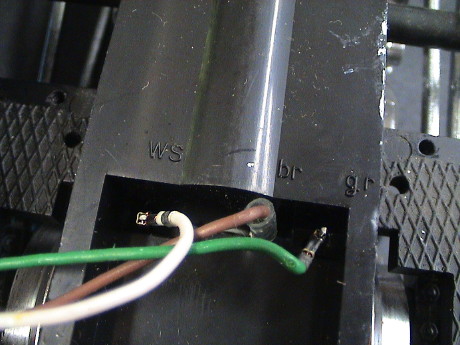 The three wires
leading from the brick are colored white (ws), brown (br) and green
(gr). The green wire is the power lead leading back to the motor. The
brown wire is track power leading up to the shell. The white wire is
the other rail and one motor lead.
The three wires
leading from the brick are colored white (ws), brown (br) and green
(gr). The green wire is the power lead leading back to the motor. The
brown wire is track power leading up to the shell. The white wire is
the other rail and one motor lead.
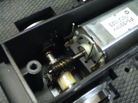 The connection
wires come up from the bottom and run through the holes in the motor
tabs. The motor will pull straight out at this point so that it is easy
to solder new wires to the motor tabs and bend them a little so that
they clear the existing stiff wires. This is shown in some detail in my
LGB 2060 Tips page.
The connection
wires come up from the bottom and run through the holes in the motor
tabs. The motor will pull straight out at this point so that it is easy
to solder new wires to the motor tabs and bend them a little so that
they clear the existing stiff wires. This is shown in some detail in my
LGB 2060 Tips page.
I normally try to keep the existing electronics during a DCC install. There are often useful circuits like a 9 or 12 volt regulator or firebox flicker circuits. However, the board in the Porter has no useful stuff left so I junked it during the DCC installation. There isn't a lot of room inside the loco, except in the cab, for electronics so junking the board makes some room where it is needed. The 5 volt electronics are not needed for DCC operation. The smoke unit is already burnt out, if I replace it at all, it will be with a 16 volt unit. The headlight has already been converted to a white LED and the cab light will be changed out to a warm white LED. All this stuff can run directly from the decoder so that the board is no longer necessary. The loco draws too much current to run from an HO sized decoder, 1.5 amps pulling and about 5 amps stalled. Room must be found for a much larger unit and the space consumed by that PWB is prime real estate.
Electronics such as a DCC decoder and/or a sound system could be installed on the walls of the cab below the windows but I don't feel the need to do this now. Further, I don't like to install decoders on removable bit and pieces. That is a wiring nightmare.
My first choice for a decoder was the Digitrax DG583S but it didn't fit. It is too wide to get into the boiler by just a little bit. I made some measurements and found that if I removed the weight at the top of the boiler, it would make a little more room, but not enough. It was time for Plan B. An NCE D408SR would fit in there, but that is a pretty expensive decoder. I did have one, and it did fit, but I have plans for that decoder in a more demanding application than the Porter. Since I put a surplus DG580L in the Lionel handcar and it didn't seem to grumble much in that lightly loaded application at my intended track voltage of 16 volts (HO standard) I figured that it might work in the Porter. Further, I had it and it fit so I used it. The DG580L has a total of 8 function outputs, one of them, F3, is good for 1 amp. I ordered a Seuthe #7 16 volt smoke unit, when it arrives I will wire it to F3.
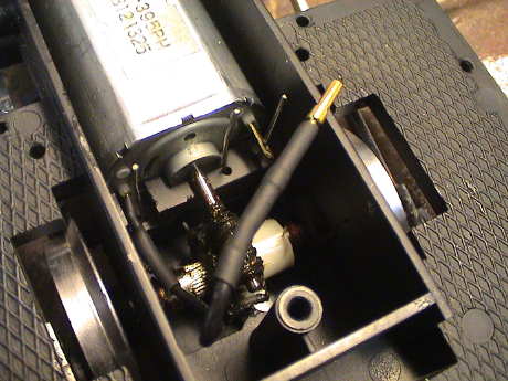 The first task during
any DCC installation is to isolate the motor leads. In the Porter's
case, one lead, the rightmost one in the photo, was already isolated
within the brick. The other one, however, is also the fireman's side
track pickup. I pulled out the motor and bent the motor tab a little so
that it would clear the post. Then I bent the post over a little to
make even more room. I soldered a wire to the motor tab and then double
insulated it with shrink tube. The wire was terminated at the other end
in a female D contact pin, see my Power Connector Tips page for more
info on these inexpensive and versatile connectors. I drilled a new
hole in the brick cover to allow this wire to escape the brick so that
the decoder can be unplugged from the brick using the 3 original
connections and the one new connection. A quick check with an ohmmeter
confirmed that the motor leads were indeed isolated.
The first task during
any DCC installation is to isolate the motor leads. In the Porter's
case, one lead, the rightmost one in the photo, was already isolated
within the brick. The other one, however, is also the fireman's side
track pickup. I pulled out the motor and bent the motor tab a little so
that it would clear the post. Then I bent the post over a little to
make even more room. I soldered a wire to the motor tab and then double
insulated it with shrink tube. The wire was terminated at the other end
in a female D contact pin, see my Power Connector Tips page for more
info on these inexpensive and versatile connectors. I drilled a new
hole in the brick cover to allow this wire to escape the brick so that
the decoder can be unplugged from the brick using the 3 original
connections and the one new connection. A quick check with an ohmmeter
confirmed that the motor leads were indeed isolated.
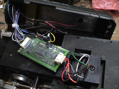
 The decoder was then
wired to the four leads. I reversed the red and black decoder leads
because the large scale track polarity convention is opposite the NMRA
standard HO convention. I connected the orange and gray leads to the
motor, not paying much attention to polarity knowing that I might have
to reverse them after I tested the loco if it ran backwards, which it
did.
The decoder was then
wired to the four leads. I reversed the red and black decoder leads
because the large scale track polarity convention is opposite the NMRA
standard HO convention. I connected the orange and gray leads to the
motor, not paying much attention to polarity knowing that I might have
to reverse them after I tested the loco if it ran backwards, which it
did.
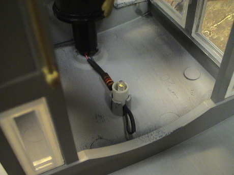 I used a warm white 3
mm LED for the cab light. The original cab light nestled into a cast
feature on the underside of the roof, the LED was much smaller than
that. However, the inner diameter of the capture feature was just
slightly over 1/4" so I grabbed a piece of 1/4" styrene tubing and
hacked off a short piece of it. I notched one end of the tube slightly
and hung the LED in the tube and glued the bent leads to the tube.
After soldering wires and a 3.3K current limiting resistor to the LED,
I fed the wires back down the steam dome where the original wires had
come from. The resistor sets the LED current at about 3 mA on the 14
VDC I expect to get from the decoder when run from 16 volts on the
track.
I used a warm white 3
mm LED for the cab light. The original cab light nestled into a cast
feature on the underside of the roof, the LED was much smaller than
that. However, the inner diameter of the capture feature was just
slightly over 1/4" so I grabbed a piece of 1/4" styrene tubing and
hacked off a short piece of it. I notched one end of the tube slightly
and hung the LED in the tube and glued the bent leads to the tube.
After soldering wires and a 3.3K current limiting resistor to the LED,
I fed the wires back down the steam dome where the original wires had
come from. The resistor sets the LED current at about 3 mA on the 14
VDC I expect to get from the decoder when run from 16 volts on the
track.
The front headlight LED had been set to run at 10 mA from 5 volts. I added another 390 ohm resistor in series with it so that it would run at about 18 mA at 14 VDC and wired it from the decoder blue wire and F0(f), the forward headlight function. I also wired connected a 10K resistor between the F0(f) and F0(r) functions so that the headlight would be significantly dimmed in reverse.
It all worked. However, the motor noise caused by the low switching speed of the DG580L decoder is somewhat of a bother. It is not as bad as I remember it when this decoder was in locos with bigger motors and running from higher track voltage, but it is still loud enough to be objectionable. I'm going to look around and see if I can find an inexpensive basic 4 function decoder that is less than 1.25" wide but will still be able to drive a 1.5 amp average and 5 amp stalled load. I don't know of one so I may end up with a D408SR anyway.
After running Daisy at the GIRR Mtn Div with DCC, it is very clear that the DG580L isn't going to last long as shown by this movie clip. At low speeds, the grinding and grumbling produced by this decoder is just not acceptable.
 Even
though I had an NCE D408SR decoder with me at the mountains, I didn't
have the instruction sheet with the pinouts and programming
information. I brought Daisy home to the GIRR and swapped the decoders.
This clip shows a rather
significant difference in the noise level that Daisy produces.
Even
though I had an NCE D408SR decoder with me at the mountains, I didn't
have the instruction sheet with the pinouts and programming
information. I brought Daisy home to the GIRR and swapped the decoders.
This clip shows a rather
significant difference in the noise level that Daisy produces.
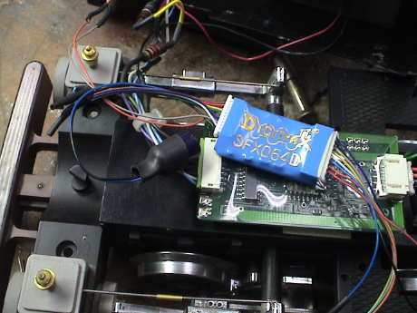
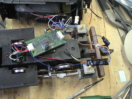 The Porter is a pretty small
loco but I managed to install sound in it as well as DCC. I used a
Digitrax SFX0416 sound and function decoder, the black blob in the
lower right. It comes with an external energy storage capacitor, the
round blob next to the coupler, to allow it to ride over minor power
pickup problems without glitching. This seems to work.
The Porter is a pretty small
loco but I managed to install sound in it as well as DCC. I used a
Digitrax SFX0416 sound and function decoder, the black blob in the
lower right. It comes with an external energy storage capacitor, the
round blob next to the coupler, to allow it to ride over minor power
pickup problems without glitching. This seems to work.
The decoder a generic steam and diesel program built in or, with a programmer, different sound files can be added. It also provides a good collection of sounds, playable with the function buttons on the decoder. What it does not provide is a lot of volume. This decoder is suitable for indoor use at max volume. Outdoors, it would hardly be heard. However, it only costs about $50 and what sound it does have is pretty good.
Since the engine is at DCC address 3, I left the SFX0416 at that address as well. The decoder provides 4 additional function outputs, but since I already had the headlight and cab light wired to the NCE D408 decoder, I didn't use any of them.
Chuff synchronization is either via a chuff cam or via DCC speed setting. Since there is little place to mount a chuff switch on this loco, I chose the speed sync method. There are a couple of CV's that allow the chuff rate vs DCC throttle setting to be adjusted. I got it acceptably close to 4 chuffs/turn without much difficulty and it seems to track well over a wide range of speed, at least as well as I can count chuffs at moderate speeds anyway.
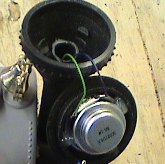 To get any hope of usable sound
volume the speaker needs to be unobscured. There is also little room to
mount a speaker. I chose to mount a "high bass" 1.06" speaker in the
smokestack. It is hot glued to the top of the stack and projects
directly upward. I had to grind off about 0.1" from the top of the
smoke unit sleeve so that the smokestack top would fit all the way on.
Even this mounting leaves a little to be desired in the volume department. It's turned all
the way up but it would be better if at least the chuff was a little
louder. This little 1" speaker as pretty good bass considering it's
size. It is far better than the 1.1" speaker that came with the
decoder.
To get any hope of usable sound
volume the speaker needs to be unobscured. There is also little room to
mount a speaker. I chose to mount a "high bass" 1.06" speaker in the
smokestack. It is hot glued to the top of the stack and projects
directly upward. I had to grind off about 0.1" from the top of the
smoke unit sleeve so that the smokestack top would fit all the way on.
Even this mounting leaves a little to be desired in the volume department. It's turned all
the way up but it would be better if at least the chuff was a little
louder. This little 1" speaker as pretty good bass considering it's
size. It is far better than the 1.1" speaker that came with the
decoder.
Even with the better speaker, the sound never met my expectations. I went through quite an exercise in trying to modify and upload a new sound project into the SFX0416. All I managed to do was to blow away the old project and fail to replace it with anything. I concluded that the decoder itself was locked up and sent it back to Digitrax for repair or replacement. In the meantime, I purchased an older Digitrax sound decoder, the SFX064D because the general consensus on the Internet was that the newer decoder had quite a bit less volume. This turned out to be true.
 The decoder itself is
similar to the SFX046 except that it is a little smaller and has a 2nd
set of function wires. It also has the 330µF charge storage
capacitor wired externally.
The decoder itself is
similar to the SFX046 except that it is a little smaller and has a 2nd
set of function wires. It also has the 330µF charge storage
capacitor wired externally.
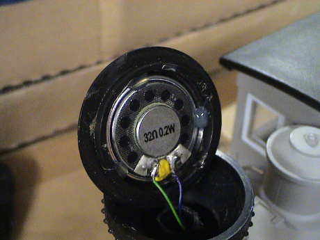 The
speaker is mounted in the same way. This one has an all plastic
diaphragm, but it seems to work well enough. Even though it is rated at
0.2 watts, it seems to be able to handle the decoder fine. This might
be a hint as to what the actual audio power of the decoder really
is.
The
speaker is mounted in the same way. This one has an all plastic
diaphragm, but it seems to work well enough. Even though it is rated at
0.2 watts, it seems to be able to handle the decoder fine. This might
be a hint as to what the actual audio power of the decoder really
is.
However, the improvement in sound volume is real as demonstrated in this clip. This decoder also has a "playable" whistle when used with the Digitrax DT400 throttle with OPsw#3=x081. The playable part doesn't amount to much. If I press the F2 button harder, the volume of the whistle changes.
I took Daisy back to the GIRR Mtn Division and taped a new video of Daisy at the same spot as it was before for comparison.
Daisy with the SFX0416 decoder installed
Daisy with the SFX064D decoder installed
There is a difference. These decoders use the same sound project so they sound the same. The "newer" SFX0416 decoder just makes less audio power than the older SFX064D.
[ Home ] [ Up ] [ Previous Page ] [ Next Page ]
This page has been accessed times since 22 Sep 08.
© 2008-2011 George Schreyer
Created 22 Sep 08
Last Updated September 5, 2011