 10 Oct 09 3 Oct 08 4 Oct 08
[ Home ] [ Up ] [ Previous Page ] [ Next Page ]
10 Oct 09 3 Oct 08 4 Oct 08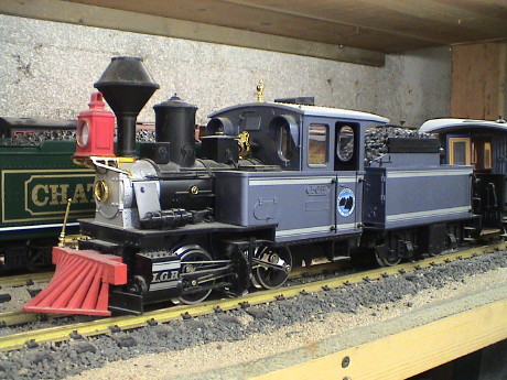 This
LGB 2017 is a starter set locomotive that I got in about 1990. This is
NOT the "D" version that been wired with DCC in mind. This one needs
some work to be able to convert it to DCC or battery power.
This
LGB 2017 is a starter set locomotive that I got in about 1990. This is
NOT the "D" version that been wired with DCC in mind. This one needs
some work to be able to convert it to DCC or battery power.
I belive that the 2017 is a variation of the LGB "Stainz" which was the loco used many of the LGB starter sets. The information presented here is probably applicable to that loco as well.
The loco itself is fine for pulling the two coaches that came in the set, but it had a tendency to slip under heavier loads even though it has a traction tire. It clearly needed some help in the form of a powered tender.
Powered tenders are popular as they can convert a fairly weak pulling 0-4-0 starter set locomotive into a very good puller at relatively low cost. The set also handles tight radius curves well. When the cross jumper cables are used, power pickup of the set is also materially improved.
The pair of them pull about as well as any small 4 axle diesel locomotive. They have also been quite reliable as I hadn't been into the mechanisms of either one in over 18 years. I did add some weight into the side tanks of the loco and I added sound and weight to the tender. Even later, I converted the engine and tender to DCC with a decoder installed in the tender.
 The
tender is pretty easy to get apart. The bottom cover of the brick comes
off with 4 screws to allow lubrication or changing the power pickup
contacts, but that's about all you do from the bottom side.
The
tender is pretty easy to get apart. The bottom cover of the brick comes
off with 4 screws to allow lubrication or changing the power pickup
contacts, but that's about all you do from the bottom side.
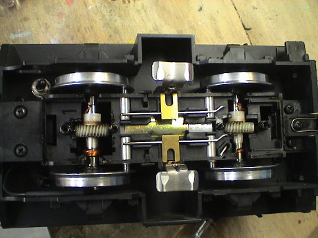
Note the metal rods running across both contacts and the skates.
These vanish up into the brick. One goes right through the brick, the
other goes through AND contacts one of the tabs on the motor. Also note
the short stub rod. This is the path downward from the shell back to
the other tab on the motor.
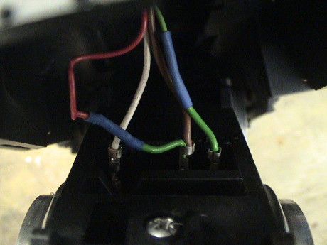 The
brick is held in by tabs molded onto the coupler mounts at both ends.
Removal of 4 screws releases the couplers and the brick. However, there
is still wiring to contend with. The contacts slip on the ends of the
rods seen in the previous photo. Note the wire colors, your's might be
different. Simple pull them off with a pair of needle nose pliers to
fully release the brick.
The
brick is held in by tabs molded onto the coupler mounts at both ends.
Removal of 4 screws releases the couplers and the brick. However, there
is still wiring to contend with. The contacts slip on the ends of the
rods seen in the previous photo. Note the wire colors, your's might be
different. Simple pull them off with a pair of needle nose pliers to
fully release the brick.
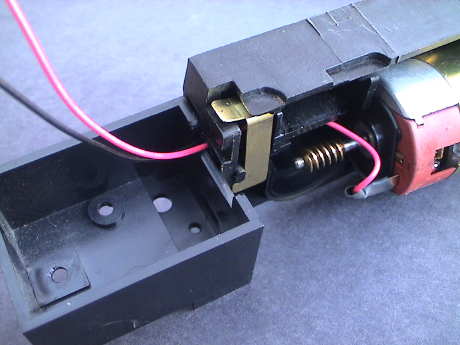
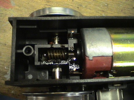 Two
more screws restrain the top cover of the brick. Once the cover is
removed, you can see the motor and it's connections. Isolating the
motor is not hard at this point, see my LGB 2060 Tips or Lehmann Porter Tips pages for a method
to isolate the motor for a battery power or DCC installation.
Two
more screws restrain the top cover of the brick. Once the cover is
removed, you can see the motor and it's connections. Isolating the
motor is not hard at this point, see my LGB 2060 Tips or Lehmann Porter Tips pages for a method
to isolate the motor for a battery power or DCC installation.
The loco itself is much more challenging to get into. The problem is that the brick is split vertically so that the whole thing has to come apart to access the motor leads to isolate them or even to lubricate the loco.
This is the step by step process that used to get the brick out. Reassembly is just in the reverse order.
Remove the smoke stack assembly by unscrewing it from the top. The nut is captive in the frame and cannot be turned by itself. If your loco has a active smoke unit, remove the screw on the rotating lug that is used to turn the smoke unit on or off.
Remove the front steps. These are residual from other models of the same loco.
Pull out the pilot.
The cab can be removed but this is not required to access the brick. It is helpful, though, to have the cab removed to facilitate rewiring.
Remove three screws under the cab. This releases the rear coupler and the rear end of the brick.
Unclip the valve gear supports from the frame on both sides.
Remove one screw that secures the valve gear assembly. The valve gear will have to be loose to access the screws that hold on the front drivers later.
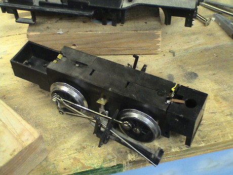
Pull the steam chest (cylinder assembly) out from the bottom of the loco.
The brick can now be pulled downward and released from the loco. Electrical connections to the shell are via tabs at the rear of the brick so no wires need be disconnected.
When I actually do the DCC installation, I'll add to these steps for disassembly of the brick itself but it is pretty clear that the drivers and running gear will have to be removed from at least one side to be able to split the brick housing. There may be other gotcha's as well, but it went together so it has to be possible to take it apart.
 I
didn't disassemble the loco any further than this point because I
didn't want to have to take it fully apart twice. This was an
investigative disassembly so that I could see what I was in for when it
came time to install DCC. It went back together again without any
serious difficulty.
I
didn't disassemble the loco any further than this point because I
didn't want to have to take it fully apart twice. This was an
investigative disassembly so that I could see what I was in for when it
came time to install DCC. It went back together again without any
serious difficulty.
A couple of weeks later, it came time to isolate the motors in preparation of a DCC installation. Therefore the brick had to come apart. This is the sequence for disassembly of the brick from the state shown in the last photo. It appears to be a good idea to keep the brick parts separate from the shell parts. This way, when you get the brick back together, you'll be able to see if you have any left over parts to make sure that it is complete before you assemble the loco any further.
Pull the rear assembly out of the brick, it will just pull out
Remove the entire connecting rod assembly by unscrewing the four hex head screws at the crankpins. Be careful not to lose these screws, they are very oddly cut and won't easily be replaceable. Work over a tray or plastic box so that anything that drops out will be captured.
Remove the two drivers on the side with the straight blade screws (the other side from the photo above). The power contacts will pop out, provided that their springs are still good, don't loose them. There are two more screws hidden behind the drivers so that these drivers have to come off. There is one phillips screw also on that side that needs to come out.
Gently pull the case halves apart, the adhesive label on the bottom may hold them together.
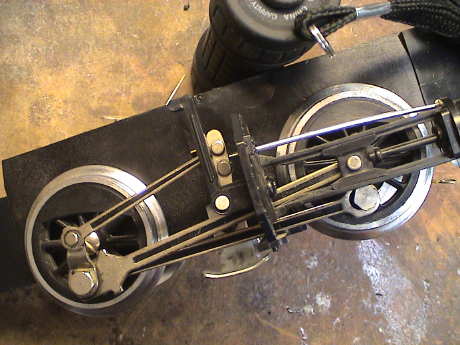 For
reference, this is the way that the connecting rods look before
disassembly. I include this photo to aid in reassembly.
For
reference, this is the way that the connecting rods look before
disassembly. I include this photo to aid in reassembly.
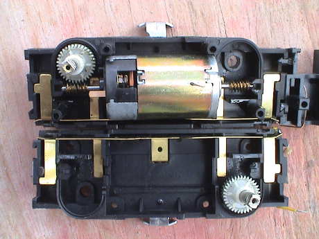 With
the case halves separated, the motor will just fall out. The motor tabs
contact two brass strips that form the internal wiring of the
brick.
With
the case halves separated, the motor will just fall out. The motor tabs
contact two brass strips that form the internal wiring of the
brick.
THIS IS IMPORTANT. When comes time to reassemble the brick, the two axles MUST be correctly oriented with respect each other or the connecting rods will not fit. The axles are keyed on each end. Make sure that the keys are parallel to each other. If not, pull an axle out of the case half and reinsert it. I can be helpful to rotate the worm by hand to make them parallel to the brick case edge so that it is easier to see when they are parallel. The keys on the other side will then be vertical. If you get the case halves back together and find that the keys are not parallel, you will be taking the brick apart again to fix it.
Before you put the wheels back on, this is a good time to inspect the brushes and brush springs. The springs should be resilient and nearly push the brush out of the brush holder. If not, the spring has been overheated and is shot. I had two obviously dead ones which I replaced with Aristo freight car truck springs. Note that the Aristo springs are colored black with some kind of non-conductive coating so that you must clean this coating off the ends of the springs or they will not provide conductivity. The Aristo springs are also just little too long. Thread them over a jewelers screwdriver and fully compress them. They will shorten by a little bit and fit better.
Installation of DCC requires that the motors be completely isolated from all other wiring. This is why I have to get all the way into the bricks.
Once the motors are isolated, the rest of the wiring can be left alone if the headlights, front and rear, are run from the decoder. Actually, other than the smoke unit and the sound system that I installed, there isn't any other wiring.
A single decoder is used for both the loco and tender. It mounts in the tender where there is more room. Also the sound system is there as well so access to the sound triggers is much easier.
I retained the existing jumper cables to connect track power between the loco and tender. I added three more wires, two for the motor and one for the headlight. The "blue" wire going to the front headlight is synthesized in the loco with two diodes so that I don't have to run a 4th wire.
It would be possible to run the loco and tender each on their own decoder and consist them so that they run together. This would eliminate the need for any further wires between the tender and loco at the expense of another $50 for a 2nd decoder. Then the tender and loco could then be converted and operated separately. However, separate operation is not really practical as the coupler between the tender and loco is somewhat custom and not much else would couple to them. A single 3 to 5 amp decoder can easily handle both motors which have a total stall current of less than 6 amps and a running current of less than 2 amps.
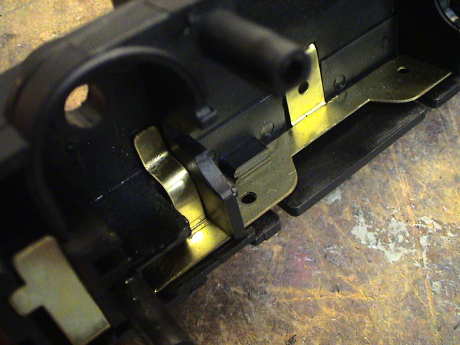 Once
the brick has been splayed open, it is fairly easy to modify the power
contact tabs so that they don't touch the motor tabs. I used two
screwdrivers, one supporting the portion of the tab that isn't bent and
another to press down near the end of the tab to form it out of the
way. I pressed it down until it is nearly in contact with the brick
housing. The hard part is getting the new wires from the motor tabs to
the outside of the brick. There isn't a lot of room.
Once
the brick has been splayed open, it is fairly easy to modify the power
contact tabs so that they don't touch the motor tabs. I used two
screwdrivers, one supporting the portion of the tab that isn't bent and
another to press down near the end of the tab to form it out of the
way. I pressed it down until it is nearly in contact with the brick
housing. The hard part is getting the new wires from the motor tabs to
the outside of the brick. There isn't a lot of room.
 There
is a path in though. I drilled a 3/32" hole directly through the back
of one half of the brick, just above the cutout in the piece that fits
on the back of the brick. I routed two 24 ga wires through this hole.
This pretty much dedicates the rear frame piece to one half of the
motor brick but this is ok because the other half of the brick will
still slide on.
There
is a path in though. I drilled a 3/32" hole directly through the back
of one half of the brick, just above the cutout in the piece that fits
on the back of the brick. I routed two 24 ga wires through this hole.
This pretty much dedicates the rear frame piece to one half of the
motor brick but this is ok because the other half of the brick will
still slide on.
 These
wires were then spliced into a 3 conductor flexible harness (swap meet
special) which was routed out the back through a drilled hole. The very
back of the shell was also notched to allow these wires to poke through
it as well. The white wire will go to one of the headlight wires. It is
connected inside with a couple of D connector pins so that the white
wire can be disconnected to allow the shell and brick to part again
should it ever be necessary.
These
wires were then spliced into a 3 conductor flexible harness (swap meet
special) which was routed out the back through a drilled hole. The very
back of the shell was also notched to allow these wires to poke through
it as well. The white wire will go to one of the headlight wires. It is
connected inside with a couple of D connector pins so that the white
wire can be disconnected to allow the shell and brick to part again
should it ever be necessary.
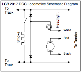 The
remaining wiring in the loco is pretty simple. The only addition is the
two diodes that synthesize the blue wire of the decoder so that it
doesn't have to be brought forward to the loco.
The
remaining wiring in the loco is pretty simple. The only addition is the
two diodes that synthesize the blue wire of the decoder so that it
doesn't have to be brought forward to the loco.
Note that in the brown wire leading to the stock headlight there is a diode to provide the directional headlight function on regular track power. The diode is wrapped in electrical tape up inside the boiler. The polarity is such that the brown wire could be connected to the F0f function of the decoder and it won't cause any problem. The black wire leading to the headlight would then be connected to the real or synthetic "blue" (+ common) wire.
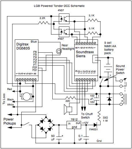 The tender is quite a bit more
complicated. It already has a Sierra in it and that has been retained.
All the rest of this stuff results from several years of experience
with the Sierra and DCC. Without the optical isolators and external
battery charging circuit, the Sierra won't keep it's battery charged
nor reliably blow the forward, backward and stop whistle signals.
The tender is quite a bit more
complicated. It already has a Sierra in it and that has been retained.
All the rest of this stuff results from several years of experience
with the Sierra and DCC. Without the optical isolators and external
battery charging circuit, the Sierra won't keep it's battery charged
nor reliably blow the forward, backward and stop whistle signals.
I've added a relay to allow the DCC decoder to enable the sound system. The system will also disable when commanded off or upon loss of track power. This allows the system to gracefully shutdown when I turn the layout off so that the Sierra battery doesn't discharge in case I forget to turn it off with the manual switch.
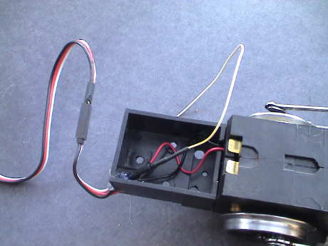
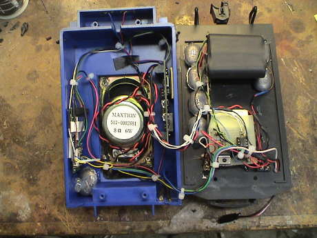 After the
interface circuit (little board in the lower right) and the DCC decoder
(left) were installed the tender is pretty full. I had to move a couple
of weights to make room for the decoder. The interface board just fits
forward of the speaker magnet. The battery just fits behind the speaker
magnet. All the wiring wraps around the speaker when the thing is
closed up. The relay doesn't show in this photo, but it's tucked into
the lower right corner of the tender shell. It all fits and it
works.
After the
interface circuit (little board in the lower right) and the DCC decoder
(left) were installed the tender is pretty full. I had to move a couple
of weights to make room for the decoder. The interface board just fits
forward of the speaker magnet. The battery just fits behind the speaker
magnet. All the wiring wraps around the speaker when the thing is
closed up. The relay doesn't show in this photo, but it's tucked into
the lower right corner of the tender shell. It all fits and it
works.
[ Home ] [ Up ] [ Previous Page ] [ Next Page ]
This page has been accessed times since 21 Sep 08.
© 2008-2010 George Schreyer
Created 21 Sep 08
Last Updated December 12, 2010