 3 Apr 11
 24 Apr 1119 Aug 116 Nov 11
[ Home ] [ Up ] [ Previous Page ] [ Next Page ]
3 Apr 1124 Apr 1119 Aug 116 Nov 11For a period of time, LGB had manufactured some air powered fantasy cars. The first was called the Fortuna Flyer. That one went over pretty well so they made a Mars Flyer, a Snoopy Flyer and a Santa Flyer. The Fortuna Flyer and Mars Flyer show up on evilBay fairly often, but they usually get bid into the stratosphere. I found a used one as a "Buy It Now" item for $110 and bit just to play with it.
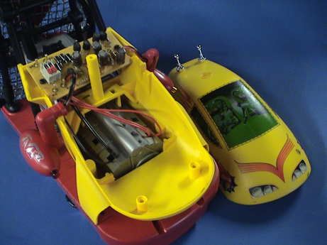
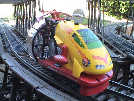 The Mars Flyer is a 4 wheel railcar with a fantasy shell and a motor powered fan drive. The wheels on this one had clearly seen some miles as they were pitted and there were some minor scratches on the fan housing, but otherwise it was in good shape. I didn't much care about the resale value as I planned on hacking on it anyway so the cosmetic problems were no big deal.
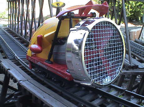 There is a three bladed fan in a fan housing at the rear. The wheels all use ball bearings to allow them to free roll and still pick up power. The instructions indicate that it is wired to accept a DCC decoder.
I did a quick check of the resistance of the motor and it is pretty low, 3Ω or a little less so it will required fairly hefty decoder. An HO sized one will not do.
I initially tested it on DC on dirty track and it didn't do very well. I had to clean the wheels and the track to get it to run very far at all. After that, I found that it would climb my 1.6% grades but it would run away going downgrade. It will take some skill to drive this thing. I shot a video of it running full out. I crashed it several times, the last crash was fatal. Two of the fan blades broke off.
I'll have more to say about this puppy once I get it running again.
 In in order to fix the fan, I had to disassemble the fan cage. Four screws need to be removed from around the outside of the cage to remove it. Two of them are blocked by the chassis. However, a small #1 Phillips screwdriver can be used to access them by flexing the fan cage just a little. The other two are not obscured.
The fan blades were first tacked back on with CA. After the CA had set, I used a filled epoxy to reinforce the joints. I applied epoxy to the unbroken joint as well just to help with the balance. I was concerned that the fan would be out of balance and tear itself apart again. It got to 16 volts before the blades tore off again while I was testing the operating current.
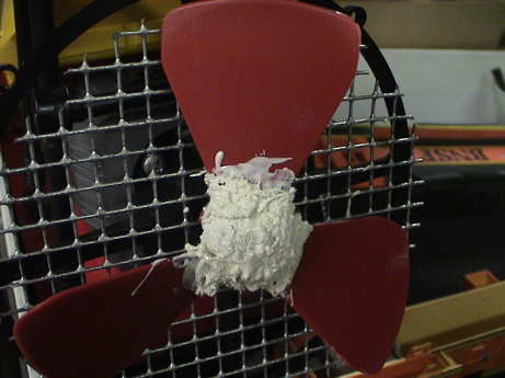 Apart it came again and this time I used a different epoxy reinforced with gauze. It looks pretty ugly and I don't yet know if it will hold together. Axel Tillman at Train-Li indicates that I can order a new fan. I might just get two.
The patch more or less works. The fan is a little out of balance, but it doesn't come apart at full voltage. If I can get a new fan, I will but I can probably get by without it.
 To get to the motor, the body must be removed. There are four larger screws and two small ones that need to be removed to loosen the shell enough to reach the motor terminals. A bar across the top of the framing at the top of the fan cage also has to be removed to allow the shell to be lifted.
This is as far as it needs to go to install a decoder. The flashing LEDs on the side pods still work with DCC on the track (tested with the DCC system in analog mode) so they can be left in place. They MIGHT cause problems with decoder programming on a programming track, we'll see about that later. However since they will run on 24VDC, I can hook them up to a decoder function and that would solve the programming issues.
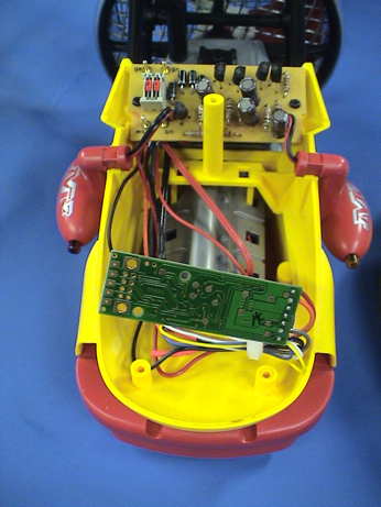
 There is an easier way to get the hood off. Remove two small screws from the front to take off the "bumper." This allows access to two more screws under the shell right at the front. Remove them. Then pull off the "antenna" on the top and remove one more screw. Then the PWB and wiring are easily accessible and there is enough room to install pretty much any large scale DCC decoder.
While I had the thing apart, I tested the unit for current draw. This is where I tore up the fan the second time. It drew 1.3 amps at 16 VDC, a little much for an HO DCC decoder. I measured the stall current by jamming a screwdriver in the screens to block the fan and ran it up to 6 volts. It drew 1.7 amps stalled. The stall resistance calculates to 3.5 ohms, about what I measured with an ohmmeter. This means that at 20 volts, the stall current will be about 6 amps, way too much for an HO decoder. Once I get the fan fixed properly, I'll try a Digitrax DH465 decoder in this unit. This decoder is physically sized to fit an HO loco but it has the current capability of a large scale capable decoder. The decoder will fit easily under the frame right behind the front bumper or inside the shell.
LGB recommends that the Mars Flyer be speed controlled by reversing the fan. This can be hard on electronic motor controllers. Slamming a regular loco into reverse is typically not a good plan. It's rough on the gearing and tends to cause derailments. The unseen issue is that when a motor is turning in one direction it is generating BEMF to buck the applied voltage. If the applied voltage is suddenly reversed, the BEMF of the still spinning motor will ADD to the applied voltage and the motor current can exceed the stall current until the motor actually stops and reverses. This is bad. The prudent thing to do is to add some small amount of acceleration momentum to the controller to allow the polarity to change in a controlled fashion so that the motor is stopped or nearly stopped by the time that the controller ramps up the motor voltage in the other direction. This will reduce possibly damaging current transients.
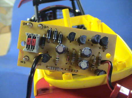 The LGB manual indicates that the unit is DCC ready. LGB describes it as a difficult install, suitable only for an authorized service station. I call it a piece of cake. After the shell is off (5 screws), the connections for the decoder are accessible. The two at the bottom left in this view are the track pickups. The two at the top left are for the motor. The two switches (shown in the DCC position) simply disconnect the motor from the track. The flasher circuit for the lamps in the side pods is permanently connected to the motor so there is no programming issue when these terminals are used. The flashers come on at the lowest throttle settings.
 The decoder install was easy. After flipping the switches as shown in the photo above, the red and black decoder wires go to the red and black wires leading to the track (one pair of wires each). The orange and gray decoder wires go to the other posts, orange on the red side, gray on the black side. I soldered the decoder wires to the back of the circuit board as I didn't have any suitable push on contacts.
I set the acceleration, CV3, to 3 and left CV4 (deceleration) at zero. This allows the fan to spin down rapidly on a reversal of power but delays the onset of power until the fan is going pretty slowly.
The flashing lights work fine and run at full intensity even at very low throttle settings when driven by the motor control signal.
With reasonably clean track, it gets enough power so that it will climb my 1.6% grades at about 55% throttle. Curves seem to bother it more than grades. This is probably because the fan is blowing at an angle relative to the motion so that the net thrust is reduced. The twisting moment caused by the off angle fan also results in more flange drag.
This puppy requires a lot of attention to control. One must be mindful of the speed and what track conditions are coming up. With speed adjustments and reversal of power for braking, it is much easier to keep it on the track than in the video above. I didn't even try to control the speed then because my TE transmitter buttons (which I was using for DC testing) were flakey and didn't work most of the time.
With a UT4 (big knob) DCC throttle, I find that on my layout I run it at full speed climbing the grades, half throttle on the flat and zero throttle coasting downhill. The thing really does scoot and if the operator is not paying complete attention, it will still roll right off the track. I now have two replacement fans in case my patch job with the white epoxy doesn't hold up.
After 6 months of working on and playing with the Mars Flyer, I realized that I hadn't done a video of the thing in action without all the crashes. DCC made the device MUCH more controllable, primarily because my DCC throttles work much better than the old TE transmitters with the flakey buttons. Any good throttle could have done as well as I only need three power settings, zero, half and full. The patched fan is holding together well so it is still in use.
The video is here. The thing does have the power to make it up my grades and as long as I keep the speed under control and the track is clear of leaves and sticks, the LGB Mars Flyer runs well and is fun to play with.
[ Home ] [ Up ] [ Previous Page ] [ Next Page ]
This page has been accessed times since 3 Apr 11.
© 2011 George Schreyer
Created 3 Apr 11
Last Updated November 6, 2011