 17 Oct 11
 15 Oct 1119 Oct 1128 Oct 1120 Oct 1118 Oct 1118 Oct 111 Dec 1117 Oct 1117 Oct 1118 Oct 11
[ Home ] [ Up ] [ Previous Page ] [ Next Page ]
17 Oct 1115 Oct 1119 Oct 1128 Oct 1120 Oct 1118 Oct 1118 Oct 111 Dec 1117 Oct 1117 Oct 1118 Oct 11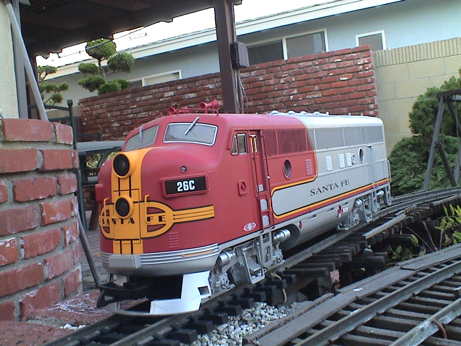 A used USAT F3A found it's way into my possession today. I wasn't planning on this, it just sort of happened. However, now I have another loco for the GIRR.
The model is of an EMD F3A which was a 1500 horsepower diesel electric loco. 1807 units produced between 1945 and 1949.
The road number of the model is 26C. By the ATSF numbering scheme used at the time, this would be the trailing cab unit of an AA, ABA or ABBA set. The lead loco would be designated 26L. After ATSF stopped running them in matched sets, each loco would receive a unique number. Some of the locos in this class were eventually rebuilt as CF-7's.
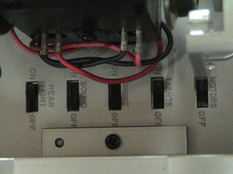 This particular model is similar to the USA Trains GP-7/9 that I purchased in 1998 but it is of somewhat newer construction. I do not know the date of manufacture, but the switch board is dated 12 Aug 1999. This one has a bank of 5 slide switches underneath as opposed to the 4 switch configuration of my GP-9. However, other than some wiring issues, it appears to be pretty much the same.
The model is well detailed and heavily built. It still has wheels with traction tires and sliders. Since my investment in this loco is really small right now, I'm not going to go far out of pocket to upgrade it so the existing wheels and sliders will stay on this one.
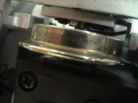 The wheels are somewhat worn indicating that this one has some miles on it. However, they are not seriously pitted now and I intend to keep them that way. My GP-9 had serious wheel problems due to a combination of conditions that I now know how to mitigate. My layout has a really beefy DCC booster which can provide very high peak currents, in excess of 20 amps. The decoder I used in the GP-9 is also a very high current decoder to match the high current motors, which the F3A still has. The combination of high available current, motors with nearly zero stall impedance and no current limiting results in burned up wheels. I'll not let that happen again.
I put the loco on my dirty track that hadn't been cleaned in more than a month and it sputtered badly. When I cleaned one section, it ran fine on that section.
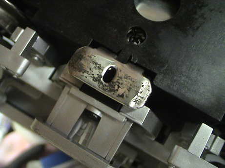 The sliders are also not in good condition, I will clean them up as they will be needed to offset the loss of 4 wheels worth of power pickup due to the traction tires.
I did some initial current draw tests on this loco. Running light on DC it drew 1.8 amps with the headlight on and smoke off. At full slip, it draws 3.4 amps. I did not try to test the stall current as I knew it would be very high and I didn't want to stress the thing by physically trying to stall it. Instead, I measured the stall resistance. At the wheels, the stall resistance is about 1 ohm. Measured at the power pickup connectors on both trucks, the stall resistance is 0.6 ohms. This results in a stall current of over 30 amps at 20 volts. This is in line with my measurements on the GP-9.
Without some current limiting as described in my Wheel Pitting Tips page, these wheels will not last long on my DCC layout.
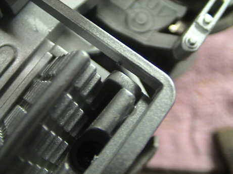
 The F3A is reasonably easy to get into if you have the right tools. It takes a long slender #1 Phillips screwdriver to reach down into the 9 places where there is a fastener. The tall posts are the locations of the screws. There are four along each side. The fuel tank has to be removed to access the center two on each side. It's the one in the front that is difficult. It is centered right in front of, and partially obscured by, the front truck. This is where the long slender screwdriver comes in handy. The front truck has to be rotated so that the screwdriver can fit between a wheel back and the brick. Then the 9th screw can be removed. The frame will then pull out but it might hang up on each side at the rear on a pin that holds the rear brake lines on. Push those details partially out so that the frame will clear.
 The strap hangers on the Blomberg type B trucks have a tendency to fall off. Over the years, I've lost two from the GP-9. I've found that a very small drop of gel CA (I use Loktite brand) placed at the bottom of the hanger will prevent the lower part of the hanger from being pushed outward which promotes the tab at the top coming loose. This very small bond will keep the hanger on but is easily broken when it is necessary to removed the hanger to access two screws that hold on the truck sideframe.
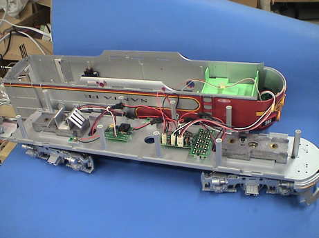
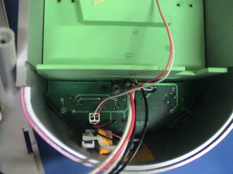
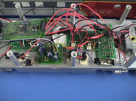
 The wiring in the F3A is pretty straight forward. In the front half of the locomotive is the forward lighting board (in the shell) and the main switch board. There is a voltage regulator for the lighting bolted to a weight in the front. Note that this regulator is not insulated from the weight so that the weight is energized at the output voltage of the regulator. Don't let other conductive objects touch the weight.
 The rear section contains the smoke regulator board with it's external regulator transistor bolted to a heat sink at the rear. This regulator is also not insulated from it's heat sink or the weight. It is energized to about the same level as track power. Do not let other conductive objects touch this assembly either. The smoke system is identical to the one in my older GP-9.
There are two spots, one on each side, with a little contact PWB to connect the back up light and the smoke units in the shell.
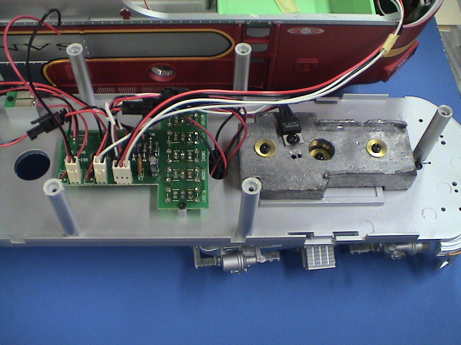
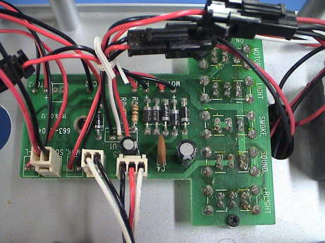 The main switch board is where most of the wiring action is. There isn't a lot on this board except for the 5 slide switches and a bunch of connectors to reach other parts of the loco.
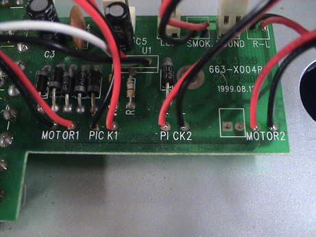 Connecting a DCC decoder for motor control is easy, all the required connections are right here. Both sets of motor wires should be unsoldered from the board and then connected in parallel, black to red, and then connected to the motor output of the decoder. The reversal is necessary as the bricks are mounted reversed from one another. Then one of the sets of pads that went to the motor wires is wired to the decoder track input and the motor part is done. The motor switch then shuts off power to the DCC decoder and therefore the motors. I have added 1.5Ω of sandstone power resistors in series with the motors to limit their peak current capability. This resistor could dissipate 15 watts under high motor load conditions so that it should be rated for 20 watts or better and physically isolated from anything that might be damaged by heat. It will get VERY hot.
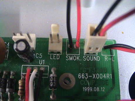 The row of connections on the other side of the board are well identified or keyed. The 3 pin connector drives the front lighting board exclusive of the LED marker lights. The one marked LED drives the bicolor marker lights. The SMOK pads power the smoke regulator. The SOUND connector provides track power to a sound system via the sound switch. The R-L terminals go to the rear headlight.
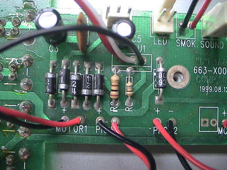 There are some parts on the topside of the board, nothing but traces on the backside. An LM317 regulator is mounted off board. There are 6 diodes. Numbered from the left of the photo, the 1st, 3rd, 4th and 5th ones are part of the bridge rectifier that converts track voltage to DC for use by the regulator. The 2nd diode provides directional lighting for the front headlights, the 6th one does the same for the rear headlight. The two resistors set the regulator output voltage to a measured 3 volts. The three capacitors are filter and stabilization capacitors for the regulator.
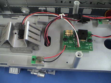
After the loco was all buttoned up, I installed track power connectors at both ends using my standard method. I was able to do this without opening up the loco. I soldered the wires leading forward and backward to the connectors on the trucks. The inner set is track power, the outer set is for the motors. Power can travel from one end of the loco to the other via the internal wiring. It is not interrupted by any of the loco's switches. This photo was taken before the new wiring was added. Note that if the new wire that you add manages to contact the motor contact, there will likely be a problem in a DCC equipped loco. Connecting a motor wire to the track will surely result in a toasty decoder. I cut some small 0.062" thick styrene shims and attached them between the motor and track contacts on each side to provide insulation so that the contacts can never touch.
 All of the lighting is in the shell and most of it is incandescent. There are two headlights, two marker lights, two numberboard lights and a cab light wired to this board. There is also another incandescent lamp on the rear of the shell.
Lighting changes in USA locos to adapt to DCC require considerable thought and planning with some potentially severe wiring changes. A DCC conversion requires changes to separate out the headlights and MARS light from this board so that they can be directly driven from a DCC decoder. The cab and numberboard lights can be left connected to the track. Since the lighting circuit is switched, those lights can be turned off to allow decoder programming.
The rear backup light is a 5 volt 56 mA bulb, it'll need a 270 ohm 1 watt resistor in series or a change out to an LED.
The headlight circuit board has virtually the same circuit as in the GP-9 EXCEPT that the bicolor LED marker lights are wired to their own isolated circuit in the F3A.
The headlights are incandescent and not very bright so they were changed to LEDs and driven by the NCE D808 DCC decoder.
The markers are bi-color LEDs that requires some work. They are wired to light green going forward and red in reverse. This may look pretty but has little prototypical function. Green going forward indicates a following section. For a single train, the forward markers should be dark.
After planning it out, this is what I did. I used the existing marker LEDs but wired to light red only in reverse. This is easy to do as, unlike the GP9, the markers are wired up to the board with their own pair of wires and are isolated from the all other circuits. The 300 ohm current limiting resistor is in the F3A, as was in the GP-9 is really too low a value for the continuous high voltage that the DCC decoder will supply. The LEDs have about the right brightness at 30 mA total (15 mA each) so I installed another 330Ω 1/2 watt resistor in series with them and then I connected the wires to the decoder function outputs instead of back to the switchboard. The black headlight wire is positive to light the red LED so that it went to the decoder blue wire.
The two headlight bulbs are wired in parallel now, they will be changed out to hard white 5 mm LEDs. The little plastic plug that holds the bulbs now can be drilled out a little to accommodate the LED lens with some minor grinding on the LED.
I used another connecterized wiring harness (All Electronics p/n CON-640) going from the shell from the frame for all the lights wired to the decoder. The cab and number board lights use their existing wiring. This makes four new wires leading to the front, the blue decoder wire and three loads (headlight, MARS light and markers). The rear headlight uses use it's existing wiring but I pulled the wires off the switch board and wired them to the DCC decoder. The lamp itself was changed to a 3 mm white LED with a 1KΩ series dropping resistor wired in series with one of the wires in the shell.
The front lighting board can be removed by removing two small screws and then gently prying the rear end of the board upward to clear a post, then outwards. The marker LEDs will fit back in the plastic diffusers in the shell.
The holder for the headlight and MARS light are a different length but in both cases, the plastic flange at the base of a 5mm LED must be ground off to fit. Further the MARS light holder needs to be drilled out with a 0.200" drill bit by hand a little deeper to allow the LED housing to settle in deep enough.
The backup light used a 3 mm LED. It gets taped back in similar to the bulb that came out. Insulating tape is required over the leads before reapplying the reflective plastic foil with more tape or the foil will short out the LED leads.
I used a 1KΩ resistor in series with each LED to provide adequate current limiting. I usually add the resistor in the blue wire side to prevent any shorts downstream from burning up the decoder or melting insulation. A typical decoder has no current limiting on the blue wire. I also added a 330Ω 1/2 watt resistor in series with the markers.
I had some difficulty getting the lower headlight to act as a MARS light. The decoder simply wasn't responding as the instructions indicated that it would. However, I was able to program the upper headlight as a MARS light so I'll use the lower one as the regular headlight. Other than that, it all worked as intended.
 The smoke system in the F3A appears to be identical to the smoke system in the GP-9 so it will need the same modifications to reduce the current and increase the reliability as the GP-9 did. See the GP-9 page for details on that conversion.
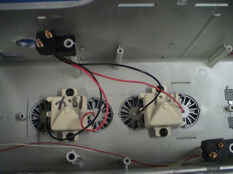 The smoke units themselves are wired in parallel. This helps them create more smoke at lower track voltage, but with DCC, there is high voltage all the time. The constant high voltage and high current stresses the regulator. It is better to wire them in series so that the current is cut in half and the regulator overhead voltage is reduced by 6 volts, the voltage drop of one smoke unit. The reliability issue is that both smoke units are driven from the current regulator. When one of them fails and opens up, the regulator will try to force the current for both of them through the one that is left and it will fail spectacularly. When they are wired in series, when one fails, the other just stops working too. The reduced current load helps prevent the regulator from getting quite as hot as well.
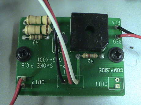
It turns out that the smoke regulator board in the F3A is labeled for the GP-9. It's the same exact board, so I did the same thing except that I didn't add the filter capacitor as it is unnecessary with DCC. It only provided an advantage with PWC which I am not using anymore. I clipped one lead on one of the large paralleled sense resistors. This increases the voltage drop of the sense resistor by 2x and the regulator output current drops by 2x to compensate.
To rewire the smoke units in series, cut the red wire going to the forward unit and the black wire going to the rear unit. Then insulate the ends that lead back to the connector. Then splice the remaining red and black wires (the ones going to the smoke units) together and insulate that joint.
This loco was converted to DCC using an NCE D808 decoder that has been in stock for more than 10 years waiting for a loco that needed it. Like the GP-9, I added resistance in series with the motors to limit the stall current that the motors can draw. At startup, when the decoder first starts making pulses, the motors are stopped and therefore simulate a stall condition until they spool up. USAT motors spool up and down fairly slowly so that these very high currents can last for a good part of a second. This is why the wheels burn. The finite contact resistance at the track, especially when other wheels are not making good contact results in high local dissipation at the very high peak currents that this loco can draw. Even an ohm of wheel to rail contact resistance can produce up to 30 watts of instant heat in a very small spot. These conditions can produce visible sparks of incandescent material being ejected from the joint.
I put 1 ohm of resistance in series with the GP-9 motors. I used 1.5 ohms in series with the F3A motors. This reduces the peak motor current to less just less than 10 amps, hopefully enough to allow the wheels to survive.
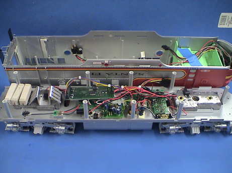
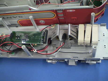 The NCE D808 decoder went in easily enough, its the long green board at the left of the photo. Three 0.5Ω resistors are wired in series and installed on top of the rear weight. They are held down by their leads which are attached to the floor by a couple of globs of gel CA. Their heat is mitigated by the length of the lead so that the CA should hold up. I overcoated the CA with a glob of epoxy and allowed it to set up overnight just to make a stronger joint.
The loco got sound. I took the cheap and dirty route on this one. I had just pulled an SFX0416 Digitrax sound only decoder out of an HO loco because it's sound volume was just too low. On the GP-9, I used another HO sound decoder, a Soundtraxx DSX which also had low sound volume. However, I added a 5 watt audio amplifier after it. This time I used an audio amp kit that I bought on the internet to boost the audio to acceptable volume levels.
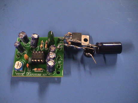
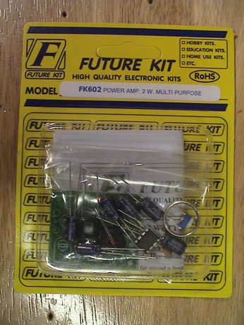 This is the audio amp kit I used. I bought it from FutureKit.com. It is their part number FK602. It costs $6 but the shipping was $10 so I bought 3 just to amortize the shipping cost a little. The amp is rated at 2 watts, but as will be described below, it doesn't quite make that spec.
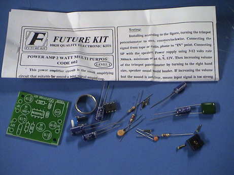 The kit is just a small single sided PWB, a handful of parts and a one sided instruction sheet. The PWB is well stenciled so that it is easy to determine where each part goes and how to orientate it. I spent less than 10 minutes actually assembling the kit.
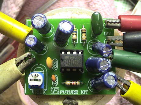 I hooked the assembled board up to a bench power supply, an audio oscillator and an 8Ω speaker. It worked right off.
 The circuit is a simple integrated circuit amplifier chip and some supporting components. It runs from 3 to 12 volts DC.
A 12 volt single ended amplifier could never make 2 watts into an 8 ohm load. In fact, it clips at 8 volts peak to peak which results in a shade over 1 watt. A full honest RMS watt is sufficient for my purposes. It does well enough. I may have to turn it down just a little with the SFX0416 remote volume control CV but for now, I am running it at full volume.
The amp I built for the GP-9 used a different, much more capable IC which runs from nearly full track voltage so it is able to generate 5 watts. It also heat sunk much better that this little part. 5 watts is WAY too much to use at full volume so I have that one turned way down so that I don't disturb my neighbors too much.
The input and output of this amp kit are single ended. This is no problem at the speaker end. However, the output of the SFX0416 is not single ended so that there the same ground reference problem that I experienced with the 5 watt amp in the GP-9. I solved that issue in the same way with a small audio transformer. This also provides a step down of the output voltage of the SFX0416 so that the decoder output voltage can get down to the 60 mV RMS that this amp wants to see at maximum gain. Gross level setting can be done by programming the SFX0416 output. Any fine trim can then be done with the volume control at the amp input.
There is a 50 kW AM radio station (KNX) only a few miles from my house. If I touch the input circuits with anything, KNX comes through loud and clear. I had to pay special attention to the input lead configuration and bypassing to prevent KNX from corrupting the sound.
 I kludged up a little 12 volt regulator from an LM317 and hung it on the side of the amp board. The thing is ugly, but due to the stiffness of the leads, it is self supporting. I mount them together with foam tape to the loco floor. The regulator makes 12.67 volts which is adequate for the amp board. I had tested it as high as 14 and it didn't blow up immediately.
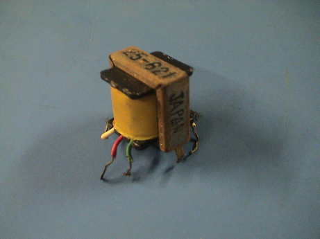 This audio transformer is pretty much an unknown part that had been in a parts drawer for 40 to 50 years. These things were common in the early days of transistor radios which is probably where it came from. The primary is center tapped and has about 200 ohms DC resistance. The secondary has a DC resistance of about 5 ohms. Since the primary and secondary wire size appear to be the same, it is possible to estimate the turns ratio at 40:1. This may be a little much as the SFX0416 makes only about 0.5 volts RMS at it's output. At 40:1, this results in only 12 mV RMS or so at the input of the amp. The amp wants 60 mV RMS.
A Radio Shack p/n 273-1380 ($3) appears to be similar and would probably work although it's turns ratio is even higher, 125:1.
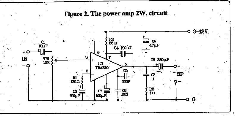
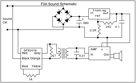 This is the schematic of the configuration that I settled on. The SFX0416 is so weak that it could not drive the amp to clipping through the step down ratio of the transformer. I therefore used only half of the primary by using the center tap and one end. This cut the turns ratio by half and then at max output, the SFX0416 started to just barely clip on the highest peaks of the sound with the horn blowing. By hooking it up to a properly enclosed speaker for testing (an old mini HiFi speaker) it was clearly making enough volume to work.
There are a few extra parts in the schematic. The 1KΩ resistor connected to the SFX0416 is to give it enough load so that it will be able to report back it's programming on the DCC programming track. I used the yellow function lead as it was already available but any of the function leads would do as well. During programming, the decoder briefly turns on all functions to draw a pulse of current that the command station can read.
The 0.01µF cap at the amplifier input was to take out KNX which came through at FULL volume after I had wired it up. With the cap there, KNX is gone. When I hooked up the input of the 3 terminal regulator (an LM317) to the DCC track voltage, a little DCC hiss got by it. The 0.1µF cap at the output of the regulator killed that off. Both of these caps are actually soldered on the back side of the amplifier board.
I used the stock GP38 sound project that comes with the decoder. The Digitrax sound project page doesn't have a lot of selection of older diesels. I'll look around more on the net for one that someone had done of an F3 or F7 but I haven't found one yet. Note that if you use the stock sound program and set CV60=1 to access the diesel project there can be a problem when new sound project is loaded. Most projects have only one sound type in them, the stock decoder has two. If you have it set to the second project and then load a new project that has only one sound type in it, the decoder will continue to try to play the now non-existent sound project at slot 1. Set CV60=0 to point it back to the first project slot.
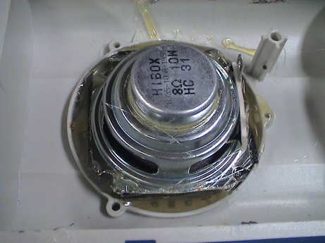 The F3A has a place for a 2.5" speaker in the fuel tank. I fitted the best speaker I can find in that spot because the GP38 sound project has quite a bit of bass in it and it could use a good speaker. That speaker is a 2" long throw automotive speaker. I had purchased a bunch in surplus. It is a little to small to cover all the slots in the grill so that the extra slots must be sealed. The speaker has a 1/4" thick foam gasket on the front so I trimmed the corners of the frame so that the speaker would fit in the round border around the grill and filled the exposed gaps with hot glue. I had taped the other side with painter's tape just in case any of the glue dripped all the way through, but none did. The glue was applied in two layers, one to mostly fill the gaps but still be unlikely to drip all the way through, and the other layer to seal the whole works. The hot glue both seals the speaker and attaches it with no chance of a rattle. The speaker is JUST short enough to fit in the tank. It clears the top of the tank by less than 1/32".
Once I had the F3A open, I found a 2 pin connector labeled for sound. I happened to have a connector and 2 wire harness that would fit. Note that the LED marker harness has the same connector. That one can be reused for the sound if the marker wiring is provided in a separate harness for the headlights. When the sound is turned on, this connector provides direct track voltage so that a dedicated sound decoder can connect right there. However, I had to connect the amplifier to the lighting circuit (so I could turn it off independently from the sound decoder) so that the load of the amplifier does not disrupt programming the sound decoder on the programming track. Between the motor, light and sound switches on the bottom, each decoder and the audio amp can be disconnected so that the other decoder can be easily programmed without the need to resort to address tricks or decoder locking. The SFX0416 does not appear to support NMRA defined decoder locking.
 I installed the sound stuff that I had lashed together earlier. At the left, the audio amp is mounted to the floor with foam mounting tape as is the storage capacitor for the sound decoder and the audio transformer (hiding behind the shell mounting post). I haven't mounted the sound decoder yet. The speaker is connected via three wire harness with a connector in the middle, one wire is not used. There was a half inch hole in the floor for the wires to get to the speaker, I've plugged that with a piece of styrene to "seal" the speaker enclosure. It all appears to work.
As I was programming both decoders and recording the information in DecoderPro, I noticed a minor problem. If the sound decoder was turned off with the amplifier left on, I got a pronounced DCC hiss from the amp. I surmised that when the sound decoder goes off, the differential impedance between it's speaker leads probably goes way up. This was unloading the input of the transformer and allowing it to pick up DCC noise. I put a 27Ω resistor across the sound decoder output to provide a fairly low impedance all the time at that point and the hiss simply went away. The SFX0416 is delivered with an 8Ω speaker but it really likes a 32Ω speaker better. This resistor approximates the load of a 32Ω speaker. I used 27Ω because it was the first similar part that my fingers ran across in a parts box. A more common 33Ω resistor would work as well. There was no noticeable decrease in volume when the resistor was connected.
When the installation was all done, I buttoned the loco back together and shot a short Quicktime video of the result. The SFX0416 sounds MUCH better with a good speaker and enough audio power than it does in a typical HO loco with a much poorer typically 1" speaker and insufficient audio power to even hear well. Other Digitrax HO decoders, such as the SFX046D, have a much better audio amplifier and at least make adequate audio power for an HO installation.
The GP38 sound set was ok, but it wasn't a 567 prime mover like the F3A had. Then it occurred to me that a GP10 was a slightly newer loco, but it still had a non-turbo 567 in it. I tried that set and I like it better. The sound set can be heard in this Quicktime video. The overall volume of the set is higher so that I needed to rebalance the horn and prime mover sound (this is not in the video). The horn is more playable but there is a bit of a sound disturbance as it switches between the start, run and stop portions of the horn. The prime mover sounds more like a 567. Instead of the volume of the prime mover ramping up at about notch 3 or so, this set has a constant sound volume during notch up, but a decreased volume during notch down.
The loco came with hook and loop couplers attached. This will not do at all. They got changed out to a set of Kadee #831 G scale couplers. The only hassle is that the screws that mounted the hook and loop couplers were too short to grab properly as the Kadee tang is thicker. I rummaged around my bench and found a pair of self-stripping screws that would fit and not bind the rotation of the mount. I did cut off the end of the tang that mounts the coupler to bring them closer in to the loco frame. That also allowed me to use the existing mounting hole.
After I put the decoder in but before I reattached the shell, I gave it a test run. It ran ok but it's pulling power is a little on the light side. It would barely move with the load of my track cleaning car which has very high drag. I had to break out the GP-9 to pull the track cleaning car to get the track clean enough to run on. The F3A is going to need some more weight. Finding a place to put it is an issue.
With the shell and speaker attached, the loco weighs 7.6 lbs. This turns out to be marginally enough to pull the track cleaning car. There is still some wheel slip on especially dirty sections were the track cleaning car drags more, but it gets through those sections. After a couple of passes around with the car, it didn't noticeably slip.
 After 3 days of on and off effort the thing was ready to seal up. All this work was done for zero out of pocket expense. Considering that the loco didn't cost anything either, this is good price for a capable, good looking and good sounding loco. The HO sound decoder does sound MUCH better than it does with HO sized speakers and it is loud enough. The motor decoder is really oversized because it doesn't have to deal with the very high stall currents due to the resistors in series with the motors. A 5 amp unit such as a DG583S could have done the job, but the D808 was handy and there was plenty of room for it.
This project was fairly complex as DCC installations go, certainly not plug and play. I understand that QSI now makes a board that is a "drop in" for the switch board that has a DCC decoder with sound integrated with it. That would have been much easier, but I would have to have bought one.
[ Home ] [ Up ] [ Previous Page ] [ Next Page ]
This page has been accessed times since 3 Apr 11.
© 2011 George Schreyer
Created 15 Oct 11
Last Updated December 1, 2011