 30 Nov 11
 20 Mar 1120 Mar 1111 Feb 1120 Aug 1111 Mar 1120 Mar 1119 Aug 1113 Feb 11
[ Home ] [ Up ] [ Previous Page ] [ Next Page ]
30 Nov 1120 Mar 1120 Mar 1111 Feb 1120 Aug 1111 Mar 1120 Mar 1119 Aug 1113 Feb 11The PCC car is a streetcar designed by the Presidents Conference Committee, a group of street railway presidents and their engineering staff. This is perhaps the only example of a committee design that was truly successful. This is primarily because the committee only defined what they wanted in a general way formed a design lab to implement those requirements.
A streetcar is defined to be a PCC car if it uses some or all of a set of 144 patents that were filed by the PCC. There were cars that looked like PCC cars, but technically were not. The patent licensing fees funded the continued development of the PCC car through 1951. There are also many more streetcars that are technically a "PCC" car by virtue of using some of the PCC patents that look nothing like a PCC car. Most of these are in Europe and were built after 1951. The PCC patents have all expired but some of them are still in use today.
1923 was the year of peak streetcar ridership in the US. The design committee was formed in 1929 to come up with a "modern" streetcar design to try to reverse the trend of lost ridership. In 1936 the first production models of the PCC were shipped. Besides updates to the PCC design, the PCC car was the only new street car design produced in the US until the US street railways died.
The PCC car was built under license all over the world and remained in widespread service for more than 30 years. There are still some running in regular passenger service in San Francisco and in other cities and museums. After the US street railways went out of business, many of the used PCC cars were shipped overseas to provide even longer service.
The PCC car was well liked by the riders for its smooth acceleration and deceleration and relatively smooth ride. Motorman liked it because it rode well and accelerated well. Street railways liked it because it brought the passengers back at least for a while. However, the lure of the automobile running on new and better roads drew the riders away again. Streetcar systems nationwide died off one by one. In the last few years, new light rail systems were built to help overcome the press of too many automobiles, but most of them run on dedicated right of way and use much newer trains of cars, often supplied by Japanese and European builders.
You can read more about the PCC at this Wikipedia link and this link about San Francisco's Historic streetcars where several PCC cars are in regular service on the Muni F line. Muni has painted up the cars in heritage colors of other street railways that had used the cars.
There was a major electric, mostly interurban, railway in Los Angeles, the Pacific Electric. The PE operated streetcar lines too, sometimes using PCC cars. However, much of PE operated more like an interurban railway with longer runs between stops and reaching out to greater distances from downtown. Also much of the right of way was private, not on the streets. Some of those interurban rights of way now have light rail on them.
Los Angeles also had an extensive true streetcar system, the Los Angeles Railway. The LARy was the first users of PCC cars in Los Angeles and eventually, it used only PCC cars.
The PCC cars ran quietly as compared to previous designs of streetcars. This is primarily due to two things. First, the wheels had rubber vibration isolators and dampers in their hubs. This materially reduced the running noise of the wheels. Second, they use hypoid gears, not spur gears as had been common before. The motor shaft runs perpendicular to the axles and the motors sit side by side in the trucks. The hypoid gears run more quietly than spur gears and they are fully enclosed in lubricated gearboxes. Therefore the gear noise of the PCC car was virtually eliminated. This motor arrangement also made it easier to make narrow gauge trucks as some street railways, such as the Los Angeles Railway were 42" gauge or narrower. The cars tended to be more comfortable than the older streetcars because they had cushioned leather seats, a major improvement over the wooden slat seats in most of the older cars.
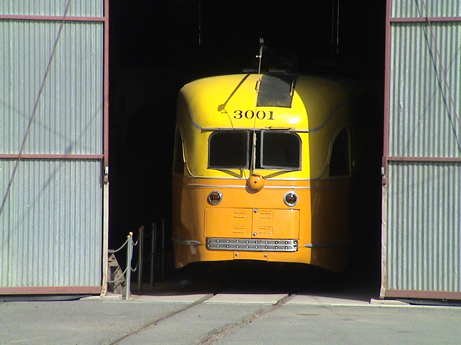 I took a trip to visit Los Angeles Railway, LARy 3001 which still exists at the Orange Empire Railway Museum where it resides in the Los Angeles Railway carbarn.
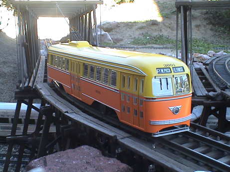
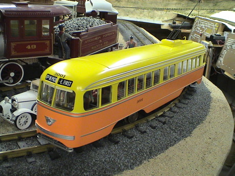
Los Angeles Railway 3001 was the first PCC car delivered to LARy in March 1937. It was among the first built and was catalog stock as delivered. In subsequent years, LARy ordered two more batches of similar cars and a final batch of slightly larger cars. The first batch was called by the LARy as the "P" car because it was intended to run on the LARy P line. The heavily traveled P line ran east and west from West Los Angeles to East Los Angeles.
 This is the first paint scheme applied to the PCC by the Los Angeles Railway, a narrow gauge streetcar line. Note that there is no "road name" on the LARy PCC car, just a number. The PCC cars didn't get a logo until the LARy was sold to the LATL (Los Angeles Transit Lines), basically a bus company. The route board above the front window indicates the ends of the P line.
3001 was the first PCC car delivered to LARy in March 1937. It was among the first built and was catalog stock as delivered. In subsequent years, LARy ordered two more batches of similar cars. The first batch was called by the LARy as the "P" car because it was intended to run on the LARy P line. The heavily traveled P line ran east and west from West Los Angeles to East Los Angeles. The route board above the front window indicates the ends of the P line.
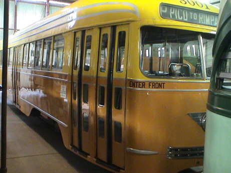
The next batch was the "P1" car which was nearly the same as the P car. Some of both batches were modified to accommodate a two man crew per a Los Angeles ordinance that required two man crews. The ordinance was later struck down by the courts. The modified cars had two seats removed to make room for a conductor's seat at the rear door. Both these cars had a 5 x 5 window configuration on the curb side.
During WWII, the "P2" or "war baby" car arrived. The P2 had a different interior due to wartime materials restrictions. The P2 car had a 6 x 4 window configuration and the rear doors were set further rearward to allow more efficient passenger flow.
After the war, a batch of "P3" cars arrived. The "all electric" P3 cars were 5" longer and 8" wider. They had a row of standee windows above the main windows. The extra width was applied to the aisle to make room for more standees and to allow better passenger flow along the car.
The very end of the green car to the right of this photo is LARy 3165, the very last PCC car, a P3 type, that was purchased by LARy.
 The P, P1 and P2 cars used air pressure for the brakes and doors. This was derived from an electric compressor. The P3 cars had all electric brakes and doors.
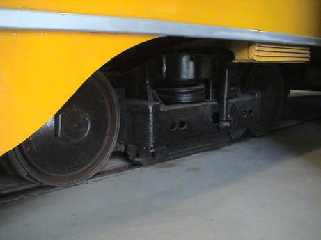
The LARy was narrow gauge, 42". This required different trucks that most PCC cars. The inset wheels didn't leave room for the more standard drum brakes so that wheel tread brakes were used. The photo shows, at the very left, the bottom of the clasp brake shoe that rides on the tread. There is an electric track brake between the wheels. Most PCC cars had their mechanical drum brakes integrated with the motor shaft.
The brakes on the car were set in three phases. Most of the braking was dynamic braking. The heat generated was recovered from the braking grid resistors and used to heat the car. At speeds below about 4 mph, outside hung brake shoes (on the LARy cars) or inside drum brakes (on most PCC cars) were applied. PCC cars used wheels with rubber vibration isolators and really couldn't handle the wheel heating of conventional train brakes unless they were applied only at very low speeds and not for very long. If extreme braking was required, the magnetic track brake gripped hard against the rails and could stop a car very quickly. The magnetic brake was not typically used in normal service.
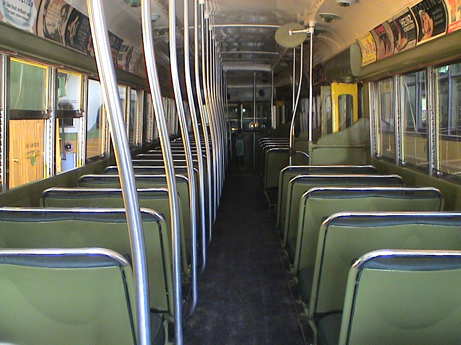 The interior of a PCC car had upholstered seats, originally leather, throughout the car. The seats did not "walk over" to change the seating direction except on a few cars that had rotating seats. This photo was taken from the very rear seat facing forward.
Above the windows were the typical advertising signs for Ivory soap, War Bonds and Burma Shave among other things.
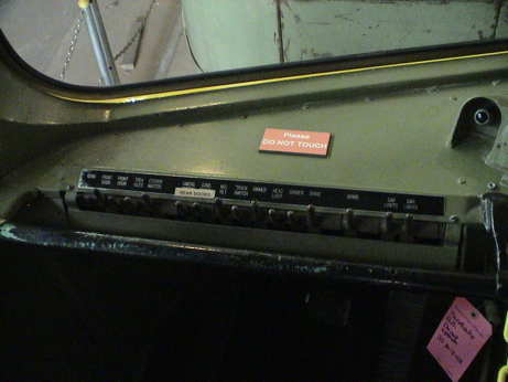 The drivers controls consisted of a row of toggle switches (doors lights and other electrically controlled circuits), three pedals (deadman, brake and accelerator) and a handbrake lever. This car has a bad order tag hanging from the handbrake lever which is why it was not running on the day that I was at OERM.
The AristoCraft PCC car was released to the world after a LONG wait on about January 5, 2011. It took me a few days to order one because I wanted to see what the paint schemes looked like for the "LA" version seen below. In the meantime, others pulled the trigger more quickly. Dave Bodner published a very good page on his PCC here. Further there have been threads on the MyLargeScale Forums posted by other early adopters.
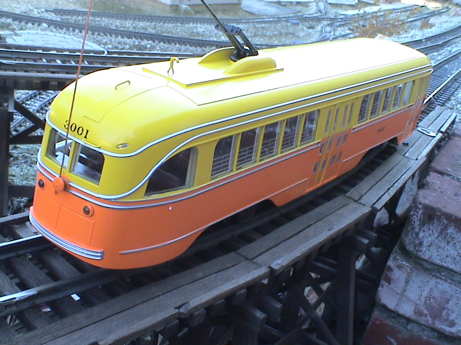
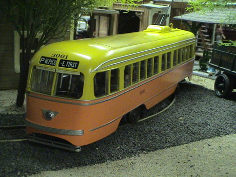
 I picked the LA car scheme. The AristoCraft model is clearly patterned after that one at OERM as the model also carries a number of 3001.
The instructions indicate that the car was modeled after a car in an east coast museum. There are some details that differ from the first LARy cars, the P and P1 cars. The anticlimber is too wide, it would have been narrower on the first PCC cars. The "life saver" below the ends of the car is modeled like a step on this car. On an LARy car would have been 3 parallel bars. This assembly was hinged. If disturbed, say by the car running over somebody, it would be pushed back and immediately shut off the power and slam on all the brakes and stop the car, hopefully before the front truck actually ran over whatever tripped the life saver. The orange paint on the lower part of the part is described as "chrome brown" in a book I have about the LARy however there are no color pictures in the book. This car is painted like the one at Orange Empire which may represent a later scheme or may just be a guess at the original color.
 The AristoCraft model is of a single ended car. Some lines chose to use "double ended" cars with a trolly pole at BOTH ends to facilitate occasional backing moves. Most PCC cars had a hostler's cab behind the rear seats. When a "single ended" car was operated in reverse, the motorman had to open the rear window and grab the trolly pole rope and help guide the trolly wheel on the trolly line so it would not snag. Some cars solved that problem with a second proper trolly pole at the front that was reliable when the car was running in reverse for extended periods.
The PCC body design was modular to some extent, the front and rear end assemblies were welded to the main body part of the car. There were some double ended PCC cars made with the cab assembly at both ends, sometimes with center doors on both sides and sometimes with only end doors. The extra center door on some cars required the rearrangement of some of the under car equipment that used the step well space on the traditional street side. Pacific Electric and the San Francisco Muni bought prewar double ended cars. The PE cars didn't have traditional walk over seats, some of the seats rotated.
Most PCC cars were single ended and required some way to turn the cars at the end of the run. Most often, this was a very tight loop, as little as 42' radius or about 3' in diameter at 1/29 scale.
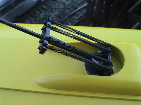 The trolly pole suspension is well detailed and provides quite a bit of upward spring force. It would keep it's trolly wheel on a pickup wire although I'm not going to use one. It will look odd, but a trolly line would not last long in my environment.
The trolly pole is restrained by a pull rope. The extended height of the pole can be reduced by wrapping some of the "rope" around the fixture on the back of the car. The knot on mine untied itself a couple of times so after I retied it the last time, I put a drop of CA on the knot. It's not coming off again without cutting the rope.
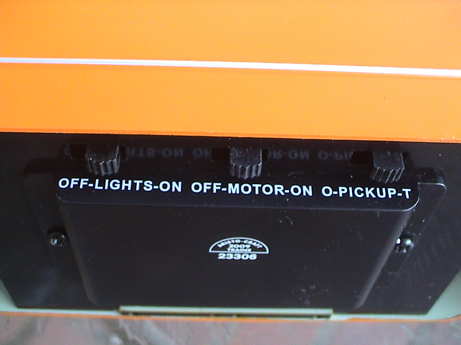 There are three switches on the bottom of the car. One to switch power to the pole, one for the motor and one for the lights. Both my motor and lights switch came in the OFF position. Further, the light switch didn't work initially. I had to play with it to get it to work and even now it is somewhat flakey.
Later, the motor decided not to work at one point and I had to jiggle the switch to get it to run. Two out of three bad switches indicates that there might be a bad run of switches.
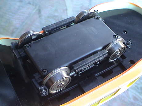 The PCC uses a totally new truck. The wheels are very small and don't have a side frame, as is correct for the prototype. The bar between the wheels is a magnetic track brake. This would have been used only for emergency stops but some streetcar lines would activate them at low current to act as draggers on the rails to allow more reliable track signal operation with less than favorable track conditions.
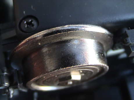 The wheel itself appears to be a cast part. I saw minimal wobble while the car was running on the bench. This wheel has had virtually no run time.
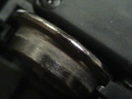 After a couple of hours of run time, the wheel is showing some wear. However, on reasonably clean track I've not seen any problem with power pickup. On dirty track, it is no worse than when it was new.
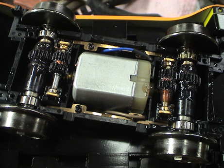 The inside of the truck reveals a relatively small motor and and an intermediate gearing setup. There is more to discuss about the truck in the Scale and Running Characteristics sections.
Note that the truck bottom cover is not symmetrical, it has to go back on with the clearances for the axle gears on the correct side.
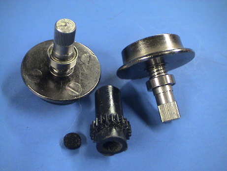
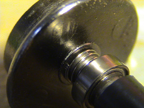 There appears to be a bead of some organic material, probably LocTite, at the root of the wheel. The wheel is probably pressed on a tapered axle end and secured with adhesive. The spring appears to provide two functions. First, it contacts the wheel itself and also contacts the inner race of the wheel's ball bearing. This provides electrical conductivity around the material that is bonding the wheel in place. Second, it also allows the entire wheelset to slip sideways to some extent and self center. The rest of the electrical path is through the ball bearing itself to the out race and then to a spring finger that contacts the outer race.
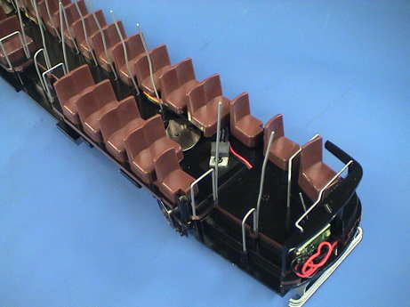 The interior of the car is fairly nicely detailed considering that visibility inward through the windows is limited. There is a regulator IC screwed to the floor near the front. This could be easily concealed with a piece of black electrical tape. After a few single seats, 2x2 seating is modeled to the rear. I have ordered a bunch of figures to populate this car so it won't go empty for long.
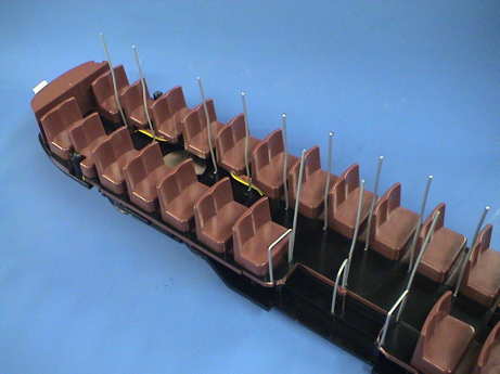 The rear of the car continues the 2x2 seating to the end of the car.
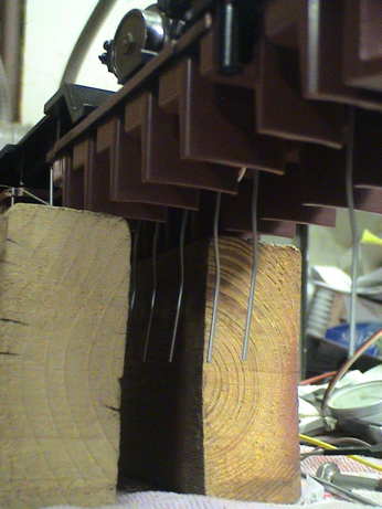 The stanchions are metal, but they are not strong enough nor do they have a wide enough footprint to support the car for service. I just used a couple of pieces of wood to support the car by some of the center seats while it was on the bench.
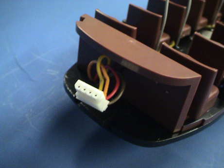 The shell comes off with 4 screws, marked in the instruction manual. However, before the shell can be removed very far, this connector for the shell lighting must be removed.
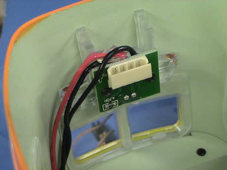 The connector plugs into this socket mounted on a PWB at the rear of the car. This PWB also contains the brake light LED and some light guides to illuminate both brake lights.
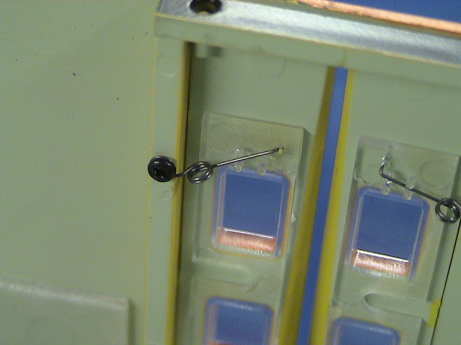 The doors on the PCC are sprung and some of them can open. All should be able to, but the spring geometry makes it difficult to operate some of them.
I measured out the PCC as closely as I could. This is not a big car. It is claimed to be 1/29 scale and it is pretty close to the pre-war cars. It has the same spotting features (window count) as the pre-war cars. I call it a 1:29 scale model of a pre-war car EXCEPT that the 45 mm gauge of the track the model runs on is 1/32 scale. The wheel flanges and tread width are also way off to accommodate reliable running on typical outdoor track.
| Measurement | Model Dimension | Car Type | Notes | ||
|---|---|---|---|---|---|
| Model | Scaled x 29 | P, P1, P2 | P3 | ||
| Length | 19" | 45'-11" | 46' | 46'-5 1/2" | Over the anticlimbers |
| Width | 3-3/8" | 8'-2" | 8'-4" | 9' | over the center body |
| Height | 4.1" | 9'-11" | 10'- 0 1/8" | 10'- 3 3/4" | At the top of the roof |
| Height | 4.63" | 11'-2" | 11'-9" | 11'-8 1/2" | At the troll pole, pole down |
| Height | 8.25" | 19'-11" | n/a | n/a | Trolly pole extended |
| Wheelbase | 2.49" | 6'-2 1/2" | 6' | 6' | |
| Wheel Diameter | 0.859" | 24.9" | 25" | 25" | At the base of the flange |
| Tread Width | 0.22" | 6.4" | 3.1" | 3.1" | twice to wide |
| Flange Height | 0.114" | 3.3" | 0.825" | 0.825" | way out of scale |
The one thing that is NOT to scale for the narrow gauge LARy is that the wheel spacing does not match the 3'-6" gauge of the LARy. It is too wide.
The wheels themselves have the right diameter but the tread appears to be too wide and the flanges are much too tall. I have a book that has many details of the LARy cars. It has a cross section diagram of the PCC wheel. Scaling from that drawing, the tread should be 3.1" wide and the flange 0.825" high as shown in the table above. The back to back spacing of the wheelsets varies between 1.595" to 1.610" which is a little wide. There is more on this issue in the Wheel Gauge Issues section below. The flange is 0.081 thick at the base of the flange. As expected, the flanges are badly out of scale.
 The PCC has some pretty long end overhang so that it overhangs tight curves more than most stuff. On 4' diameter track, the outside overhang (measured from the inside of the outside rail) is 1-5/8" while the inside overhang was only 1". On 2' diameter track, the outside overhang is a whopping 2.5" and the inside overhang is 1-5/8".
Even with these overhangs, the PCC falls within the envelope of a Bachmann Big Hauler, Shay or Heisler so that the car didn't bump anything on the GIRR Mtn Division.
Overall, the PCC runs well and with little running noise except in particular conditions. The DC current is very low, the lights draw fully half of the total current.
I have not experienced any derailment problems with the PCC.
This trolly seems to exhibit an issue that has been described by others. At low speed, it's speed is unsteady and it makes a repeating change in the gearing noise as can be seen and heard in this QuickTime Movie.
The cause of this issue appears to be because the trucks do not start at exactly the same speed (as tested on the bench with a DC power supply). On mine, the rear truck starts first and appears to run a little bit faster until the speed picks up a little. This may be due to stiff gearing that will loosen with break in. The varying gear noise results from the trucks bucking each other while loading and unloading the gear train. Instead of panicking about it, I'm going to give the PCC a chance to break in some before I declare a problem.
Note that the PCC does NOT make this sound when running on rollers. On rollers, the trucks cannot interact as they can run independently. When on the track, they CAN interact and the PCC still makes that noise on the track. This is further evidence that the trucks are bucking each other. This may or may not improve as the PCC breaks in.
Also note that the pulsing gear noise only occurs when running in either direction downgrade. It does not occur running in either direction upgrade. It does occur, although not nearly as much, on the flat and not at all on rollers.
The interior lights are quite bright. There are 20 LEDs spaced down the length of the car. The headlight is also an LED and it is pretty bright. At night, the light coming out of the windows is much brighter than the headlight so they will have to be toned down. Some light also projects out of the bottom of the car along the edges of the body and they leave the image of arcing wheels, but it's just downward directed interior light interacting with the tie strips.
The brake lights are driven by a PIC microprocessor and are programmed to illuminate as the trolly slows. This only happens if a medium speed is reached during forward running. There are red running lights to the rear.
The headlights, running lights and brake lights are non-directional.
At higher speeds, the unsteady running goes away and it runs smoothly with very light audible gear whine. The gear whine doesn't sound too different from the whine that a real PCC car makes. On rollers, it is hard to hear the whine at all.
The top speed of the car is pretty low, I would estimate about 35 to 40 mph. This is also within the range that could be expected from a real streetcar.
 The instructions indicate that the car will negotiate 20 inch diameter curves. This is pretty tight. I have a 24 inch diameter trolly line at the GIRR Mountain Division. When I tested it there (QuickTime movie), I found that while it did stay on 24" diameter curves, it did so with great complaint. It actually barely ran on the 24" diameter curves because the Bachmann power supply that drives that line just didn't quite have enough soup to drive the PCC with it's decoder analog converted. There is a little extra truck rotation available so it might actually stay on 20" diameter track.
It also surged quite obviously on a straight grade. The movie shows the tendency of the car to surge on downgrades. Surging is common with drive mechanisms that use worm gears. On this 4.2% grade the PCC surges as badly as pretty much anything I have found. Also since the trucks do not run at exactly the same speed, the PCC will also surge a little on the flat. In this case, the faster truck is substituting for the acceleration due to the force of gravity.
The flange drag or wheel slippage drag is bad enough to slow the car somewhat on 4' diameter curves. The drag gets really severe on 2' diameter track.
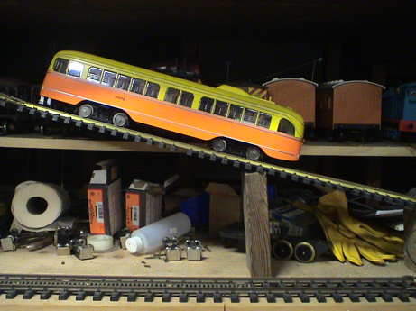 After the car had been converted to DCC and sound added (see below) I noticed that the car resisted being pushed on level track. The coefficient of sliding friction was much higher that I had experienced before. This meant that it might have good traction so I ran a quick test. I propped up my test track on anything handy until the car would almost slip back down the grade and then ran it uphill. It climbed that grade without wheel slip. The grade measures 20" run a 5" rise or 25%. This is highly unusual for an adhesion only locomotive of any kind. This is rack rail territory. I shot a short QuickTime movie of the test. It really does climb a grade over twice as steep as I have ever seen anything climb before.
I also noticed that on oxidized brass track, I can barely even push it. The wheels simply do not want to slide. After I ran the drywall sander over a section just once, the PCC would slide but still with considerable resistance. The indoor track in the video above is clean. If it was dirty, the PCC probably would have climbed an even steeper grade.
Also when the track is oxidized, the trolly has some power pickup issues, it will stutter and sometimes stall. One pass with a drywall sander cleans off much of the oxide and any particles that might be there and the trolly runs fine.
The tendency of the car to not slip will increase the drag in tight turns. Since wheelsets with hard axles, like the PCC has, MUST slip one wheel or the other in a turn, the excellent traction is actually a liability.
After some serious running hours, the PCC still makes some of the gearing sounds in the videos above, but not as badly. It will also do it running on the flat or even upgrade so that the trucks still are running at slightly different speeds.
The back to back spacing of the wheelsets varies between 1.595" to 1.610" which is a little wide. I did notice the tendency of the PCC to hop at some specific places on my layout, especially at the rear truck where one wheelset has the widest gauge. This is shown in this QuickTime movie. After checking the worst of those spots I found that the track was undergauge for short stretches. The out of spec wider gauge of the trolly and the out of spec narrow gauge of the track were interacting. At those spots, the flanges would bind and be forced upward, resulting in a hop or wobble. When the track was fixed so that it was in spec, the problem went away.
The slightly overgauge wheelsets cause another problem, significant flange drag in tight turns so I took a wheelset out to investigate if it would be possible to regauge the wheelsets. The short story is, not without a some work. The first thing to try was to see of the half axles could be pressed into the axle gear a little more. I gently pressed the two worst ones in a vice and they yielded a little, maybe 5 mils, but there seemed to be a hard stop. There is probably an insulator inside the gear that the half axles are bottoming out against. It might be possible to pull the half axles out of the gear and grind the ends off a little. I'm not going to try that until I know that I can get replacement wheelsets or parts. The next most direct approach would be to chuck the wheelset in a lathe and turn the flange back a little. This would also indicate that I would need backup parts in case I messed up a wheel.
After I had squeezed a few mils from the worst two wheelsets I ran the PCC on the GIRR again, video taping it's progress to document the remaining places that it still wobbled. There appear to be fewer places left to fix. Just taking out a few mils was enough to get it past spots that I had not actually fixed before.
 I was waiting for some other brave soul to disassemble the wheelsets so I didn't have to take the risk of breaking them. Greg Elmassian did this first as described at his PCC page. He went to considerable trouble to reface the wheels and thin the flanges on a lathe, but the main problem was just the length of the plastic gear. I don't have a lathe and if all I got was a better back to back spacing, I'd be happy.
It was easy enough to pull the wheelsets apart, file down the length of the gear and reassemble them. I got what I wanted and now it runs with no hops or jumps. I'll find out later if it does better on tight radius track.
My process was pretty simple and required only the most basic of hand tools.
Remove a wheelset from a truck. It is helpful to push down on the intermediate gearset while removing the wheel set. Clean most of the grease off with a paper towel and then hold the wheel set inside the wrapped towel and pull. One will come out. There MAY be a small plastic disk trapped in the towel, don't lose it. Hang the wheelset from the jaws of a vice and use the needle nose pliers to press downward on the end of the plastic gear to force it off. DO NOT apply force to the toothed portion. It may take some force, but it will come off. Measure the length of the gear, mine were all 0.880". The gauge is set by a ridge on the half axle riding against the end of the gear, therefore reducing the gauge requires that the gear be shorter. Since I wanted to take 30 mils off the back to back spacing (1.605" --> 1.575") I needed to take 15 mils off each end. I simply ran the end across the surface of the mill file until the gear was 0.865" long and then turned it over and took off the other 15 mils to get a final length of 0.850". I then pushed the half axles back into the gear (remember to reinsert the little plastic disk) and pushed them together by hand. They came out just right. The whole job took about 15 minutes.
It occurred to me that the unusual traction that the PCC car exhibited might have been do partially to flanging pinching on the track. However, another test after the gauge had been changed showed that the car's ability to stick on sloped track was virtually the same.
I took the regauged PCC to the GIRR Mtn Div for another test. I find that it is improved. It no longer slows on R1 (4' diameter) curves and the flanges are not bound against the rails as they were before in the curves. It runs better, but not well on the 2' diameter curves on the trolly line. It still drags to a stop in places but it makes it through most of the loop.
The current drawn by the trolly is very low. It could probably use an HO sized DCC decoder.
| Test Case | Voltage (Volts) | Current (mA) | Notes |
|---|---|---|---|
| Running light | 18 | 150 to 200 | Varied with time and load, lights off |
| Slipping | 18 | 700 | Restrained by hand but not stalled |
| Hard Stalled | 10 | 1,700 | Stalled by hand |
| Hard Stalled | 18 | 3,000 | Stalled by hand |
| Lights | 18 | 240 | Motors off |
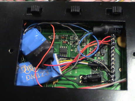
The PWB under the PCC is going to be somewhat difficult to remove to trace out so I am not going to do that now. It does have an LM2940CT-5.0 low dropout 5 volt regulator mounted in the passenger compartment. The regulator provides power to the PIC microprocessor for the brake lights, all the shell lighting and the headlight. The sign board and the running lights run from +5 volts. The interior lights are powered by an IC that steps up the voltage to about 15 volts to drive strings of LEDs.
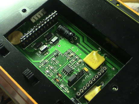 The car has a "standard" AristoCraft DCC socket underneath. However, there are a couple of issues. This socket is under the center of the car inside a fairly small compartment. An AristoCraft Revolution RX will fit in there, as probably will a Digitrax DG383AR decoder. A QSI sound decoder is simply too tall. It will hang out of the bottom of the car unless the car and decoder are modified as described in Greg Elmassian's PCC Car page.
Also, there is a small header near the center of the board which has some pins sticking out and a jumper. This connector is for programming the PIC microprocessor, the small 8 leaded package. Those pins are long enough to reach the bottom of a decoder plugged into the standard socket and MIGHT short to it, with likely unpleasant results. Dave Bodner shows how the pins could be bent over to prevent interference.
The other major parts on this board are:
| Pin Number | Decoder Wire Color | Wire Function |
|---|---|---|
| 1 | N/C | Left Rail |
| 2 | Red | Left Rail |
| 3 | Orange | Motor |
| 4 | N/C | No Connection |
| 5 | N/C | No Connection |
| 6 | N/C | No Connection |
| 7 | N/C | No Connection |
| 8 | N/C | No Connection |
| 9 | N/C | No Connection |
| 10 | Gray | Motor |
| 11 | Black | Right Rail |
| 12 | N/C | Right Rail |
The 12 pin socket at the left of the photo is the active part of the interface. It has a jumper plugged in with the last 4 pins on each end shorted. This allows the car to run on DC. Provided that AristoCraft hasn't done something funny concerning the pinout, this is what it SHOULD be based on the configuration in their SD45 and other locos with this socket. I have not verified this yet.
The instructions that came with the car indicate that the jumper on 5 pin header near the middle of the PWB must be removed if a decoder or RX is connected to the car. This is to allow the brake lights to work with the decoder or RX installed. However, in my experience, it doesn't work the way it is described. The jumper must be left in to allow the brakes lights to work at all with a DCC decoder installed.
Pin 1 is on the "street" side of the car, away from the doors. Note that in large scale, the polarity of the track is reversed compared to HO so that the red and black decoder wires, along with their matching orange and gray motor wires are reversed from HO practice.
Also note that F0 (headlights) function will not control the headlights so that there is no point in wiring the white and yellow wires.
The decoder blue wire would not be used. The blue wire normally powers accessories such as lights, but the PCC powers it's own head and tail lights. The interior lights are not wired to this socket and would not be controlled by the decoder. Be sure to turn them off when programming a decoder on a programming track.
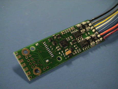 I initially elected to use a Digitrax DH465 decoder in the PCC. This is a 4 amp decoder that will fit in there, BUT it will require insulation to make sure that the decoder PWB traces are not allow to contact any PCC traces.
The current load of the PCC is small enough such that a 1 amp HO style decoder, such as a DH163 would probably work. The stall current is maybe just a little high so I first tried to use the DH465 which would easily handle the load. The DH465 also has a socket on it to take an SFX004 SoundBug sound decoder, as described below.
 When I actually went to install the DH465, I discovered that it was marginally too long and with the SoundBug attached, it was way too long. I wired in a DH163 instead because I had one available. It worked but the headlight function did not control the headlights. Then I realized that the PCC is not wired for that function. Since I also had a DH123 with a burned out headlight function, I wired it instead with just the track and motor wires. It worked fine. Note that the brake lights don't appear to work with the 2 pin jumper pulled as described in the instructions. With the jumper in place, the brake lights don't go off when the PCC stops. This will require more work to figure out. See the lighting section of this page for updates on the brake lights.
After considerable testing and blatant abuse including hard stalls, the DH123 is holding up well. This is a $15 decoder, there is no need to spend more unless you want the plug and play capability of the $45 DG383AR.
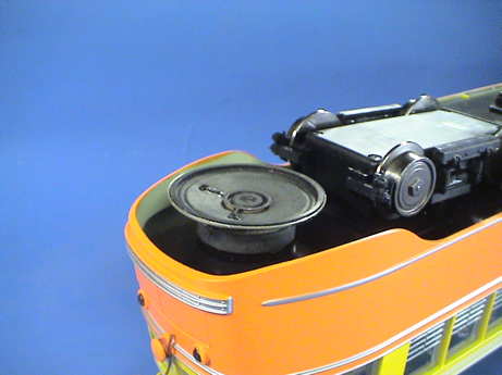 The areas under the rear and forward ends of the car are marginally big enough for a 2" speaker. There is just 1 inch of clearance between the floor of the car and the track. This is where I plan to install a low profile speaker.
The 2" speaker shown is 620 mils thick and will clear the track by about 350 mils when the enclosure is built. Painted black, it should not be too obtrusive.
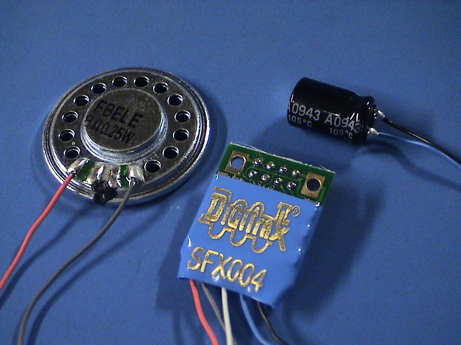 The SFX004 sound decoder doesn't make a lot of audio power, but it may be just enough with a good external speaker. I have a custom PCC sound project for it that was developed by Fred Miller.
I used the pccset.spj sound set version as it has proper sounds for both the pre war and post war versions of the PCC car. The version that plays is selected with CV60. 0 in CV60 plays the prewar set, 1 plays the postwar set. Pre WWII PCC cars used air brakes so that there was an electrically driven air compressor. Post WWII, most PCC cars were "all electric" in that they had electric brakes all around. However, running 600 volts from the trolly wire to the brake system was not safe or practical so a motor/generator set was used to convert the 600 volt traction voltage to something lower and easier to handle. A set of backup batteries powered the brakes and doors even if the trolly pole skipped off the wire. I am partial to the prewar sound set as the compressor is odd sounding and the post war motor generator set running all the time is kind of boring. Also, the paint scheme for the car represents the paint that the LARy used on the earlier cars. Newer and repainted cars had a green paint added.
The SoundBug doesn't need the DH465 to operate. I can wire it directly from the track pins on the DCC connector and then to the speaker. The track power wires are soldered to the pads in the corners (the ones with the large holes). I programmed it before installation. Since the DH123 is wired to pins 2 and 11, I can wire the SoundBug to pins 1 and 12 and then cut pin 1 or 12 from the connector header so that I can unplug it individually. Both the motor and sound decoders have a 4 digit address of 3001, the motor decoder has a 2 digit address of 3 and the SoundBug has a 2 digit address of 4. This allows me to program them separately in OPS mode without actually messing with the wiring.
With the decoder set to max volume, there is just enough sound level as it is. At some points, I can start to hear some distortion from either the decoder or the speaker. Fortunately, the parts that distort are the voice annotations that Fred added when CV60 is reset. Normal operation does not induce distortion.
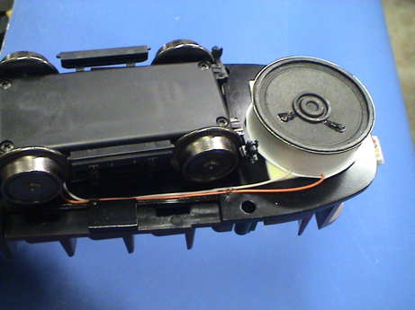 The 2" speaker is about as big as it can get and still fit underneath and not interfere with the rear truck as it rotates. I assembled a small enclosure from 15 mil styrene sheet. A 0.5" wide strip is formed into a ring and attached to the rear of the speaker. It is a little smaller than the speaker so that it fits onto a shelf on the back of the speaker basket. It is easy to seal with CA this way. A 2" circle of styrene is cut to form the back. This piece fits nearly flush to the back of the speaker magnet. A glob of gel CA on the back of the magnet (to support the center of the thin disk used on the back) and a fillet of CA around the edge hold it in place and completely seals the enclosure. The enclosure itself is attached to the car with double backed foam mounting tape.
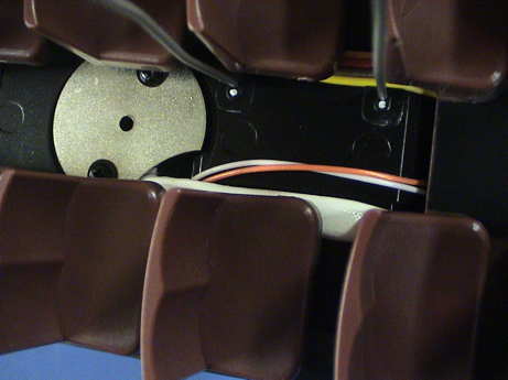 The speaker wire is routed along the frame (tacked in place with gel CA) and feeds up the hole in the frame used by the truck wiring. It runs across the floor for a short distance and then dives back under the frame, again following the path of the truck wiring bundle. From there, the wires are inside the bottom cover area where the SFX004 resides.
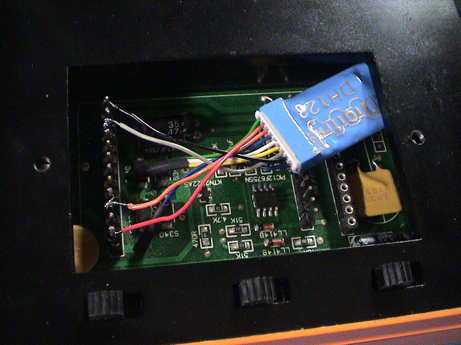
 The SFX004 is very small and can be tucked in there nicely. It comes with a 330µF storage capacitor to make the sound system resilient against short power drops. The leads on the cap are not insulated and will cause troubles if they touch something electrical. I slip a piece of 3/8" shrink tube over the capacitor to insulate the leads, but they could be insulated individually with 1/16" shrink tube. The connector end of the SFX004 is insulated with a piece of 1/2" shrink tube.
Testing outside confirms that the sound level is just loud enough with the master volume control set to max (CV58=15). This is good enough. I shot a short QuickTime Movie of the sound as installed.
To get the sound and motion of this decoder pair to match fairly well, I needed to set CV's 2 through 6 to zero for both decoders. This turns off any acceleration, deceleration, startup voltage, and maximum voltage controls for BOTH decoders. Then I set the acceleration and deceleration rates to 5 for the motor decoder only. I also had to set CV2 to 20 to get the trolly to start at speed step 2. I leave speed step 1 to activate the sound system so that the two starting bells kick in just before the trolly starts to move. The deceleration rate of 5 more or less coordinates the brake squeal at stop with the actual motion. If I approach a stop very slowly, the squeal sounds before the trolly stops. If I slam it to zero, the squeal sounds after the trolly stops. If I make a reasonable stop, then the sound and motion occur together. I did all this at my outdoor track voltage of 22 volts. If the track voltage changes, for example to 14 volts which what is normally on my test track, the sound and motion become less coordinated again.
The SFX004 burned up for no apparent reason while running on DC so I sent it back to Digitrax for repair. I tried a LokSound Select 74318 PCC decoder but it apparently has problems.
I returned the LokSound Select for reprogramming with a new sound file and as of yesterday, it had still not been returned. I gave up and installed a DH163 motor decoder and the replaced SFX004 sound decoder. I reinstalled the same sound file as before and it worked fine. If the LokSound decoder ever comes back, I can plug it in as it is an easy swap.
The LokSound Select did come back and it was unchanged. ESU explained that it was the motor generator set but I've never heard one that sounded anything like that. It is unacceptable so the Digitrax stuff went back in and the Select got returned to be reprogrammed for a steam loco where it works well.
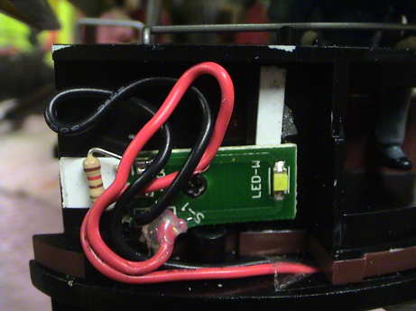
The AristoCraft PCC car uses LED lights all around. Power for the shell lights comes up a harness connected to this PWB at the back. The PWB also contains the brake light LED. I have not traced out the connector pinouts, but their function can be deduced. One pin is +5 volts from the regulator on the car floor. Another pin is the 5 volt return. Another pin has to be used for the trolly pole. The last pin has to be the power to the brake lights from the PIC on the main board. This means that the headlight, which is NOT in the shell, has to have it's own power source.
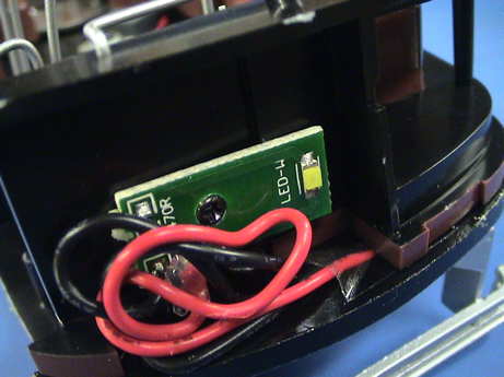 This is the headlight, a surface mounted white LED with a 470Ω ohm current limiting resistor. The headlight is mounted on the chassis and shines through a port on the shell. Since the headlight is pretty constant brightness on DC, there must be some sort of regulator in there somewhere to set a constant system bus. The resistor is marginally too low to be used from large scale track voltage but is about right for a 15 volt source. I don't see any parts for such a regulator on the visible side of the main PWB, but they may be on the other side of the board.
Then it occurred to me that perhaps the headlight DID run from the +5 volt bus at low current. A quick check of the voltage drop of the resistor showed that it dropped 2 volts and the LED dropped the other 3 volts. This implied that the LED was running at 4 mA, not 20. I soldered at 120Ω resistor across the 470Ω surface mount resistor that was there. This produced a parallel combination of 95.6Ω. I fired the PCC back up and the resistor now dropped 1.9 volts and the LED was MUCH brighter. The voltage drop went down because the LED voltage increased from 3.0 to 3.1 volts at the higher current. This produced a current of slightly under 20 mA, the likely rating for the LED.
 After the headlight intensity had been increased, I gave it a test run at night. The light was pretty bright but seemed to be off angle with the brighter beam pointing slightly to the right. I pushed out the headlight lens from the inside and the LED was well centered left to right in the headlight hole. Then I realized that the way that the headlight PWB was mounted, the LED was pointed toward curbside. There is a 50 mil high ridge behind the LED portion of the board, but nothing on the curbside end of the board to keep it pointed directly forward. I glued a 60 mil shim to the frame on the curbside end of the board and another 10 mil shim at the top as the board seemed to be point upward just a little.
I retested the PCC with the lens removed and the beam was now fairly uniform as projected on a piece of paper held about a foot in front of the PCC. I ran the car in the dark that way and I found that the headlight illuminated the area immediately in front of the car fairly well but didn't have much "punch" in that it didn't shine down the track very far. It was gone in about 3 feet.
I put the lens back in and found that then the beam tightened up considerably and would shine down the track for 15 ft or more. The surface mount LED does not have as tight a pattern as one with a molded in lens. The plastic lens was really acting like a lens. It is pretty thick, the flat inside end of the lens rests directly in front of the LED and gathers up much of the light generated by the LED. It then focuses the light to a fairly good beam that works well when the LED is actually pointed in the right direction.
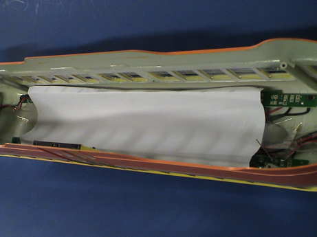
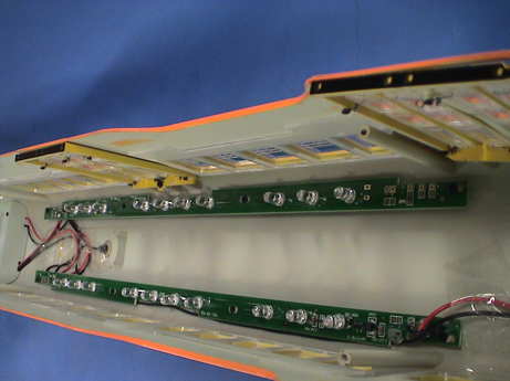 The interior lighting is way over done with 20 white LEDs. The interior LEDs draw 2.5x the headlight current each and there are 20x as many of them. The total light output of the interior lighting is 50x that of the headlight. The interior lighting LEDs are arranged electrically in four strings with 5 LEDs each in series. There are two regulator ICs, each drives two strings.
The route board light above the windshield is illuminated, it is apparently powered by +5 volts from the left lighting strip. It is pretty dim so it's current cannot be very high. The red running lights at the rear are powered from the right lighting strip board, also apparently from 5 volts. The two lights are probably fed from a single red LED and some plastic light guides. I have not been inside the covers at either end to look however. Both lights would each have their own current limiting resistor.
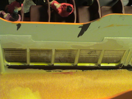
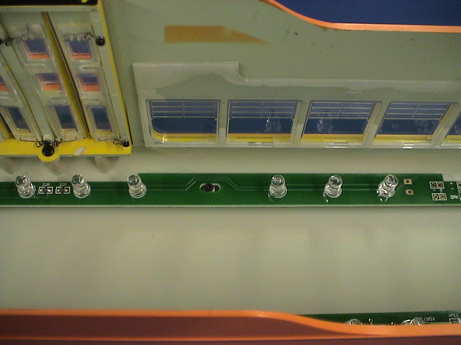 The interior light strips are each powered by their own current regulator. The 5 rightmost LEDs in this photo are wired in series. The other 5 on that side form another series string. There is a 22Ω resistor in series with each string to provide some balance of the current between the strings.
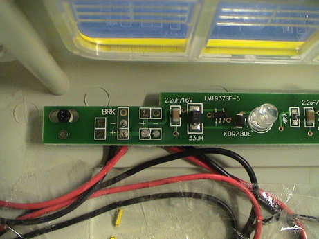 The two strips of LEDs are powered from the 5 volt bus in the PCC and use the LM1937 white LED step-up converter IC to provide enough voltage to power them. There is one regulator on each board. The IC is a load current regulator with the load current settable between zero and 20 mA. At currents below 4 mA, the circuit may cycle skip and the lights may flicker to some extent. The setpoint is set with an external resistor. For 20 mA, this resistor should be 4.75Ω. There is a 4.7Ω resistor (4R7) on the board. This is it. It is set for one string at 20 mA but AristoCraft has used two strings in parallel, so they get 10 mA each if everything is working well.
Removal and replacement of the 4.7Ω resistor with a value of 20Ω should reduce the current to the minimum that the chip can handle without cycle skipping and possible flickering, just less than 5 mA. It is possible to provide programmable dimming via a PWM or DC signal applied to the circuit, but since that signal isn't available on the board, resetting the resistor it is the most practical approach.
A 5 diode string should have between 15 and 16 volts on it depending on the actual forward characteristics of the diodes used. The regulator is designed to handle up to 6 white LEDs. In that case it would produce between 18 and 19 volts.
After considerable mucking around with this approach, I gave up on it. In theory, this works. In practice, not so much. The issue is that Aristo uses two parallel strings on each regulator. Due to individual diode variations, the voltage drop and relative intensity of the diodes varies at low current. When there are diodes in the string that leak and have lower voltage drop, they don't light up quite as quickly vs. the string current than the other LEDs. Then that total string voltage is not quite as high as the other string. The one with the bad diode and lower string voltage hogs most of the shared current and it stays bright while the other string goes dim. I could rebalance the strings with larger series balancing resistors, but it may not actually work well enough. The regulator itself is doing what it is being asked to do but it was not designed to handle two parallel load strings.
If one wanted to reduce the current to the strips AND equalize it better so that the two strips share current, then the 22Ω resistors near the center of each board is the place to attack. To get the "proper" level of lighting, in my opinion anyway, the diode current should be about 3 mA. The current regulator should be set to 6 mA (18Ω for the current set resistor) and the 22Ω resistors increased to 1K each. This will increase the drop of the resistors to 3 volts producing the same drop as another diode. The regulator is specified to handle 6 diodes in series so it would increase it's output voltage to about 18 volts to drive 6 mA into the parallel stacks. However, there might be some diodes in the strings that don't produce much light at the lower current as is the case of at least one diode in my PCC. The surface mount chip resistors used by Aristo can be unsoldered by hand by gripping the resistor with a pair of tweezers and working both ends with a very fine soldering iron tip. New leaded resistors can be soldered back to the pads by forming their leads to match the pads. You'd have to change 6 resistors to make this change.
I've returned the circuit to the as shipped configuration except I lost the 4.7Ω chip resistor so I substituted a leaded resistor. Instead, I am going to use view blocks to attenuate the light. This will be a mechanical change using sheets of paper as attenuators. It'll also diffuse the light some more.
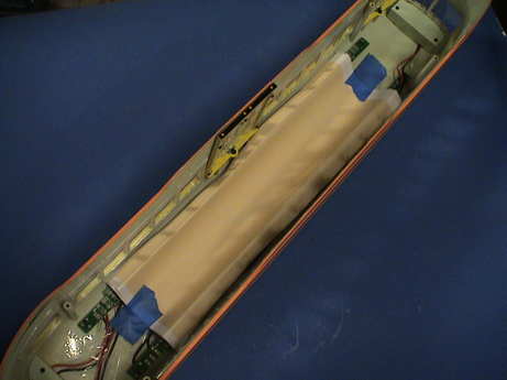
 I cut a sheet of plain old copier paper 3 1/4" wide and 11" long. I then folded down the long edges on both sides for about 1/4". The fold fits over the LEDs while the center of the sheet is taped to the inside of the roof at both ends. Since the stanchions in the car extend nearly to the roof, the filter sheet must be flush with the roof near the centerline of the car. Measurements of the light intensity coming out of the bottom of the shell with the shell removed from the frame indicated a 3 EV (8x) reduction in light intensity as measured with a Pentax SpotMeter. I reassembled the car and tested it outside in the dark. The windows are not nearly as bright, now I can actually see that the headlight is doing a good job. But they are still too bright.
I put in a second sheet of paper and that toned down the lights a little more but not nearly as much as the first sheet did. In any event, the lights are not overpowering now. I think that I'll leave it that way.
It occurs to me that the view block paper strips could have advertising placards printed on them so that the advertising that is commonly placed above bus and streetcar windows could be visible through the windows on the other side.
 Stan Cederleaf tried this method but he used a sheet of "orange tissue paper" left over from Halloween decorations. He got a very nice color. I tried it too, but instead of some paper color that I would have to search for, I just printed up a sample of various filter colors on an inkjet printer until I found a shade that I liked. I had trouble getting the right shade and opacity in one sheet, but I found a color that worked well when two sheets thick which can still be printed on one sheet of paper. The result is in this .pdf file. Due to the noted inability of cheap inkjet printers to accurately reproduce a particular color, you milage may differ. This worked well for me. Simply cut it on the dark lines and fold on the dotted lines and tape it in place.
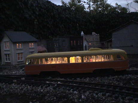
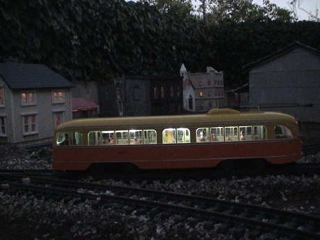 At twilight, I took a series of photos, this was the best one that shows the revised lighting. It is still too bright and there is some leakage that is illuminating the windows directly so that they show up as too blue. I have to make yet another pass at this.
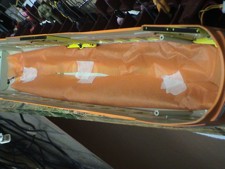 I found a package of "autumn" colored tissue paper at a local Michael's craft store. Instead of making nicely folded filters for each bank of LEDs, I used a wider strip, two sheets thick, that spanned the whole length of the car. I lifted the lighting boards and literally trapped one edge of the sheets under the boards. I then wrapped the other end back toward the center and the car and taped that edge to the roof. I want no possibility of light leakage around the filter. The photo shows that configuration. I found that the lights were still too bright and a little too pink so I added yet another single layer of yellow tissue across the whole car and fastened it down with tape, but I had to tack the edges to the car above the windows to hold the edge in place. I used CA for the tacking agent. This produced a more mellow color that was a little dimmer yet.
 Even with the LEDs fully filtered by three sheets of tissue, the top edges of the nearby windows were still absorbing too much light leaving a bright edge at the top of each window. I painted the top and inside top edge black to block the light that was being intercepted by the exposed edges of the window strips. This was not easy to do because the top edge is not visible. I dragged a brush held parallel to the roof along the top of the window strips to mask them and then also painted the edge right above the window proper. This materially reduced this highlighting but didn't completely eliminate it on the windows opposite the center doors.
 This is the result in similar lighting conditions to the 3rd photo above. The color is substantially altered and the highlighting at the tops of the windows is substantially reduced.
The brake lights worked as advertised when I was testing the unit on DC. However, after the DCC installation, the lights no longer worked. The instructions indicate that the 2 pin jumper on the 5 pin header should be pulled if an RX or decoder is installed. I did that, no joy. Also, with the jumper plugged in, the lights are on most of the time.
Pins 4 and 9 of the decoder connector would normally be for headlights but a decoder wired to those pins has no control. Further, the pins appear to be not connected to anything I can probe on the PWB so I suspect that they are not even hooked up.
I did find that the brake lights respond if I make an abrupt change in direction while running at speed, but only going from reverse to forward. Doing an emergency stop doesn't do it. Also, connecting a 200Ω resistor from either pin 4 or 9 (the headlight pins) on the DCC connector to the "ground" (center of the diode stack furthest from the connector) on the PWB doesn't have any impact.
After seeing a note on the web about the brake lights working better than mine with a Digitrax DG383AR installed, I put the jumper back in as he did and I found the same thing. When stopped, the lights are on all the time. They extinguish a few seconds after about 7% throttle is applied. They then stay off until the trolly slows some, maybe a 10 point reduction in speed where they come on again for a few seconds and go off. They can come on and off as the trolly is slowed in steps until the trolly stops where they come on and stay on. This isn't how they are supposed to work, but it's better than being off as they are with the jumper removed as indicated in the instructions.
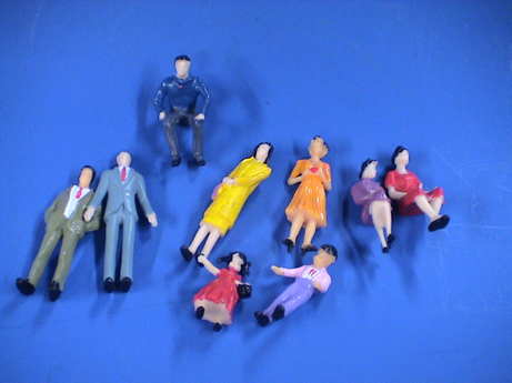 An empty PCC car would be a little odd unless it is sitting in a carbarn. I bought a batch of 1:30 scale figures on evilBay for about $0.50 each including shipping from China. There were 100 figures in the batch of ten basic types. Each type came painted in a variety of colors. There are three adult male figures, two standing in suits and one sitting in casual clothing, three adult female standing figures, three adult female sitting figures (only two shown), one male child standing figure and one female child standing figure. The faces are not painted and the detail is minimal, but for figures sitting inside a car, they will do fine. I plan to put 15 or so in the PCC and the balance in my heavyweight cars. The distribution of figure types seems to be somewhat random. There are lots of women and kids, but only three sitting male figures. I guess that the standing male figures will have surrendered their seats. One of the sitting male figures will be the motorman.
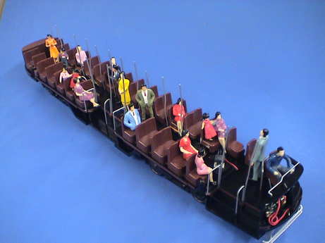 I installed 19 passengers in the car. Since I had so few seated male figures I elected to cut the legs off some of the standing male passengers. Further, except for the seats where there is lots of leg room, the seated female passengers won't fit either so I put them where I could without cutting their legs.
My work on the PCC car is about done. It's got DCC, sound and passengers. The lighting has been modified to suit my taste. Now it's time to run the wheels off it.
[ Home ] [ Up ] [ Previous Page ] [ Next Page ]
This page has been accessed times since 21 Jan 11.
© 2011 George Schreyer
Created 21 Jan 11
Last Updated November 30, 2011