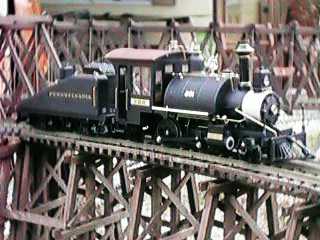
Aristo Rogers 2-4-2 Tips
[ Home ] [ Up ] [ Previous
Page ] [ Next Page ]
 The 2-4-2 Columbia type got its name because one of the
first ones manufactured was exhibited at the World's Columbian
Exposition at Chicago in 1893. The engine type was generally not very
successful and not many were built. The 4-4-0 American and 4-6-0 Ten
Wheeler types tracked better at speed due to their 4 wheel leading
truck and the 2-6-0 Mogul type was generally bigger and provided better
traction in freight service due to more weight and six drivers. The
Columbia was just too small to take advantage of the larger firebox
that the trailing truck allowed. The real advantage of the trailing
truck was realized later in the larger Atlantic, Pacific and Mikado
class engines.
The 2-4-2 Columbia type got its name because one of the
first ones manufactured was exhibited at the World's Columbian
Exposition at Chicago in 1893. The engine type was generally not very
successful and not many were built. The 4-4-0 American and 4-6-0 Ten
Wheeler types tracked better at speed due to their 4 wheel leading
truck and the 2-6-0 Mogul type was generally bigger and provided better
traction in freight service due to more weight and six drivers. The
Columbia was just too small to take advantage of the larger firebox
that the trailing truck allowed. The real advantage of the trailing
truck was realized later in the larger Atlantic, Pacific and Mikado
class engines.
The Rogers 2-4-2T did find a home in some eastern elevated and
suburban railways. The engines were small but still handled several
wooden coaches. The trailing truck, which did not support an extended
firebox, allowed the engine to track well going in reverse which
allowed the engines to work well in push-pull service. The engines
usually carried their own coal and water to negate the need for a
tender. Since the rail lines were usually short, the engines were never
far enough away from fuel and water to make a tender necessary.
When the major eastern cities eventually outlawed steam engines on
urban lines, the Rogers 2-4-2 engines were put out to pasture and
replaced with electric traction.
The Aristo model of the Rogers 2-4-2 has not been manufactured in
about 8 years. The original model was a 2-4-2T but apparently so many
people added tenders that Aristo decided to forgo the coal bunker and
include a switcher type slope back tender with a very basic chuff only
sound system.
The 2nd generation model has also been mechanically updated. It has two motors, one
for each axle, and two traction tires. The overall detail has been
improved in the retooling process. All the grabs and piping are
unpainted brass wire. The drivers now have metal tires and plastic
centers. Additional weight has been added. Gear and motor noise are
imperceptible.
There is a 3rd generation model which has been updated to accept a DCC decoder or Train Engineer receiver. I have not seen one of these.
The engine runs very well indeed and its pulling power is very good
for an engine this small. See my Tractive Effort Tests Page for the
Rogers pulling performance as compared to several other engines.
I've run some other comparisons against an LGB 0-4-0 with a powered
tender and the Rogers barely outpulls the LGB engine, even with only 4
drivers vs. the LGB's 8 drivers.
Contents
Scale
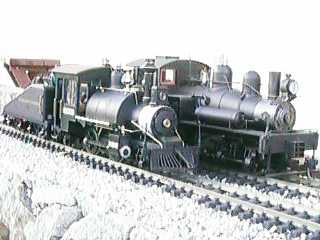 Aristo has labeled the box that the
Rogers comes in as #1 Gauge, 1/29 scale. However, my eyeballs tell me
that this engine is far from 1/29 scale. I don't have any drawings of a
prototype Rogers 2-4-2, but setting this engine next to a Bachmann
1/20.3 scale Shay looks reasonable. For example the cab door is 3-3/8"
tall, or a little over 8' tall at 1/29 scale. A 1/29 scale Kareem Abdul
Jabbar would have no trouble getting into the Rogers cab.
Aristo has labeled the box that the
Rogers comes in as #1 Gauge, 1/29 scale. However, my eyeballs tell me
that this engine is far from 1/29 scale. I don't have any drawings of a
prototype Rogers 2-4-2, but setting this engine next to a Bachmann
1/20.3 scale Shay looks reasonable. For example the cab door is 3-3/8"
tall, or a little over 8' tall at 1/29 scale. A 1/29 scale Kareem Abdul
Jabbar would have no trouble getting into the Rogers cab.
 Putting the Rogers next to a 1/29
scale Pacific really shows the difference. This little engine should
look like a toy next to a heavy Pacific, but it actually taller and
wider. The Rogers would look right at home on a turn-of-the-century
narrow gauge layout, but on a more modern 1/29 scale layout, it
wouldn't fit well.
Putting the Rogers next to a 1/29
scale Pacific really shows the difference. This little engine should
look like a toy next to a heavy Pacific, but it actually taller and
wider. The Rogers would look right at home on a turn-of-the-century
narrow gauge layout, but on a more modern 1/29 scale layout, it
wouldn't fit well.
The Rogers stands 6-3/4" tall from the railheads and is 4-3/4" wide
across the cab roof. The engine and tender are 23-1/2" long from the
rear step to the tip of the pilot.
[ Top ]
Power Pickup
When I first got the Rogers, I dropped it onto my track and ran
pretty well, but it sputtered some. Since it had rained the day before,
the track was covered with splashed grit and the engine didn't like it
one bit. One pass with a track cleaning car, and the engine ran
well.
The Rogers picks up power from all 8 wheels via carbon brushes.
These brushes have lower drag than I usually experience with LGB type
contacts.
Running on the same dirty track, the Rogers didn't do quite as well
as a Bachmann Shay (which has outstanding power pickup reliability) but
it did well enough.
After extended running, the engines wheels got dirty and needed
cleaning. This is a common problem with Aristo steam engines. There is
something about the wheel material that seems to attract dirt and makes
wheel cleaning a common chore. The pony trucks really do pick up
significant power. Just cleaning them and leaving the drivers dirty
will result in a significant improvement.
As of late 2000, Aristo has released replacement drivers for the
Rogers made of a new material. If this is the same stuff that the new
0-4-0 wheels are made of, then there will be an improvement in power
pickup reliability. The improvement that the drivers can provide is
somewhat tempered by the traction tire on the rear set. Since the
crankpins are of different length, a second front set cannot be
substituted for the rear set.
Before I changed out the wheels, I ran the Rogers a bit and it was
showing definite signs of needing the wheels cleaned, even with the
tender wheels being used for power pickup too. After I changed the
wheels, and without cleaning any of the others, the engine ran much
better even with the tender disconnected. I ran it for about half an
hour and the power pickup didn't seem to be degrading. I'll need to put
many more hours on it before I'll really know how much better it is.
With the old wheels, a half hour of running was enough to get it to
start sputtering.
Replacing the drivers is a fairly straightforward task. Remove the
crankpin screws and remove the connecting rod. The wheels may have to
be rotated some to get access to the screws. It is easiest to do the
work if the crankpins are at their lowest point. Then remove the wheel
screws, lockwashers and the indexing washers. Use a flat blade
screwdriver to gently pry off the wheels making sure that you don't
lose the carbon brushes behind the wheels. Then press the new wheels in
place with the crankpins in the same position. The wheel with the
longer crankpin and traction tire goes to the rear. Before you press
the new wheel home, make sure that the carbon brush is in place, it may
have popped out when the old wheel was removed. Note that there two
slots next to the axle hole, these have to line up with the slot in the
axle. The indexing washer has a ridge that goes into these slots and
locks the wheel to the axle. Your new wheels should come with a split
ring lockwasher, use it even if there wasn't one under the old screw
head. As you tighten the axle screws rock the wheel slightly to be sure
that the indexing washer seats properly. The new wheels may also come
with a replacement axle, you won't need it.
The wheel spacing of both the pony trucks and the drivers are such
that several of them can sit on the plastic frogs of cascaded turnouts
or crossings. Add this to some dirt on the remaining wheels that are
sitting on the track and the traction tires on the rear drivers which
limit their effectiveness in picking up power, and the engine can stall
in some places. This seems to only be a problem with tight radius
turnouts.
Since the tender also picks up power on all 8 wheels for the sound
system, I wired it across to the engine following the technique show in
my Power Connector Tips
page. After this was done, much of the power pickup troubles went away.
However, the tender wheels get dirty too and eventually, they all need
cleaning. Maybe someday, Aristo will release replacement wheels for the
tender in the new material, maybe even with ball bearing pickups.
The connector wires are easy to attach to the tender, simply solder
them to the lugs that are behind each journal box. On the engine, its a
little more difficult. The power pickups on the rear pony truck are the
likely places to connect the wires. However, the brass bushings for the
brushes are encased in a plastic holder and soldering directly to the
exposed surfaces of the bushings would surely result in a melted brush
holder. Instead, I cut the wires about 1/2" away from the pickups and
stripped both ends of each wire about 1/16" I then soldered the ends
back together along with the wire leading to the power connector.
[ Top ]
Tracking and Derailments
The leading and trailing trucks are sprung and I initially
experienced no problems with derailments on 4' radius curves. The
drivers initial did not rock with respect to each other. However, they are designed to. The gearboxes for each driver are arranged to rotate slightly but mine were so still that they were effectively fixed. Some working of the mechanism by hand freed them up a little so that the axles could rock to follow wavy track.
When I brought the engine to the GIRR Mountain Division and ran it
on 2' radius curves, it had some minor tracking problems. On curves,
the inside wheel on both the leading and trailing trucks tended to lift
off the rail. The leading truck would lift going forward, the trailing
truck would lift in reverse. Sometimes the springs would fully extended
and sometimes they would bind and not fully extend. The wheel lifting
appears to be a result of the fact that the trucks don't actually guide
the engine through curves. When the body of the engine cocks to the
outside upon entering a curve it puts a lot of pressure on the outside
pony truck wheel. As a result, the inside wheel is lifted a little
until the whole engine settles itself into the turn.
This didn't actually cause any derailments but it is clearly a
precursor to one, especially if the track is not level. The problem is
due to the travel limit of the pony trucks. They are allowed to swing
just far enough to deal with 2' radius curves when the engine body is
lined up on the track centerline. When the engine body is cocked with
respect to the track centerline, the pony trucks can hit their travel
limit stops. This tends to force the engine back into line, but it also
causes the inside wheel to lift.
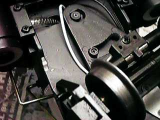 I've
gouged on my Rogers a little and fixed this problem. The front pony
truck is fairly easy to fix. Remove two screws that hold on the cover
to the truck pivot and lift out the truck a little. Use a fine file or
a small motor tool cutter to remove some plastic at the ends of the
curved slot as shown in the photo. Trim the truck until the truck can
actually touch the cylinder head. You may also have to remove a small
amount of plastic from the frame where the truck edge touches it. This
shows as a white spot on the photo.
I've
gouged on my Rogers a little and fixed this problem. The front pony
truck is fairly easy to fix. Remove two screws that hold on the cover
to the truck pivot and lift out the truck a little. Use a fine file or
a small motor tool cutter to remove some plastic at the ends of the
curved slot as shown in the photo. Trim the truck until the truck can
actually touch the cylinder head. You may also have to remove a small
amount of plastic from the frame where the truck edge touches it. This
shows as a white spot on the photo.
The rear truck is a little more difficult to remove. One of the
cover screws is obscured by the mount for the power pickups. Remove the
screw that holds the pickup assembly in place and carefully remove it.
Be sure to restrain the carbon brushes as the internal spring will push
them out when they get free of the wheel. Then gently pry out the
mounting bracket for the brush assembly. The sides of the mounting
bracket have tabs on them that if pressed inwards from the bottom will
release and the mounting bracket can be pulled out. Then remove the
truck and do the same slot widening as with the front truck. You may
also have to trim some plastic from the upper rear outside corner of
the truck itself so that it can clear the screws that mount the cab
steps.
A different kind of tracking problem occurred because of another
typical Aristo problem. The screws that hold on the drivers got very
loose which allowed the drivers to spin on their axles at times,
especially in those same tight turns. This caused the drivers to on
each side to rotate with respect to one another and the siderods would
bind. The result is that the engine would grind to a halt in tight
turns. After the driver mounting screws were tightened and the driver
quartering rechecked, this problem went away.
The drivers are indexed by a ridge on the back of the washer under
the driver mounting screw. When the screw gets loose, the driver will
no longer be locked in position with respect to the axle. Aristo has
sent me some split ring lock washers to put under the screw head. These
seem to be working in keeping the screws in place. If this doesn't work
in the long run, a little Purple LocTite 222 on the screws will
definitely hold them in place. Don't use anything stronger than 222 or
you will never get the screws back out if you should need to.
The pony truck wheels on my unit seem to be just a bit under gauge.
This didn't seem to cause a problem until they ran through the LGB 1200
turnouts where I had shimmed the
guard rail to solve derailment problems with wheels that were slightly
over gauge. On the turnouts with the thicker shims (40 mils) the under
gauge pony trucks would bind between the shim and the wing rail next to
the frog. This would cause the pony truck to squeeze upward and derail.
Turnouts that had been treated with a thinner shim (20 mil) worked
better so I have been replacing the thicker shims with the thinner
ones.
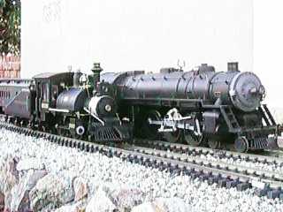
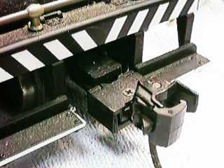
 I noticed
another problem with the Rogers. It doesn't like to push heavy loads on
2' radius track. The drawbar in the engine is mounted on the rear pony
truck. When coupled to a slopeback tender, the force applied to the
rear pony truck while pushing a heavy load would tend to derail it on a
curve. This photo shows that the spacing between the tender and the
engine is fairly tight during pushing but the drawbar still takes up
the entire load. However, if the spacing could be reduced just a
little, the frame members on the engine and tender would touch and take
up part of the load. I considered body mounting the drawbar, but after
playing with the drawbar position with the rear truck derailed so that
it could be centered, it became obvious that the width the loop on the
tender was not wide enough and the engine would probably derail the
tender truck. Further, body mounting the drawbar would be a
nonreversible modification and if it didn't work out, I would be stuck
buying a new pony truck.
I noticed
another problem with the Rogers. It doesn't like to push heavy loads on
2' radius track. The drawbar in the engine is mounted on the rear pony
truck. When coupled to a slopeback tender, the force applied to the
rear pony truck while pushing a heavy load would tend to derail it on a
curve. This photo shows that the spacing between the tender and the
engine is fairly tight during pushing but the drawbar still takes up
the entire load. However, if the spacing could be reduced just a
little, the frame members on the engine and tender would touch and take
up part of the load. I considered body mounting the drawbar, but after
playing with the drawbar position with the rear truck derailed so that
it could be centered, it became obvious that the width the loop on the
tender was not wide enough and the engine would probably derail the
tender truck. Further, body mounting the drawbar would be a
nonreversible modification and if it didn't work out, I would be stuck
buying a new pony truck.
 Moving the
engine drawbar was quite easy and completely reversible so I decided to
try it to see if it worked. A new screw hole is drilled in front of the
original one and the drawbar is simply attached to the new hole.
Moving the
engine drawbar was quite easy and completely reversible so I decided to
try it to see if it worked. A new screw hole is drilled in front of the
original one and the drawbar is simply attached to the new hole.
 In the
depth of a 2' radius curve where the side forces on the pony truck
would be the highest, the frames of the engine and tender touch and
take up the load. The drawbar actually fully unloads at this point.
This seemed to fix the derailment problem. The forces on the pony truck
are still pretty high when the engine is coming into or out of the
curve and the frames are not touching but it doesn't seem to derail.
Maybe the drawbar could be pulled forward as far as it would go and it
might work even better.
In the
depth of a 2' radius curve where the side forces on the pony truck
would be the highest, the frames of the engine and tender touch and
take up the load. The drawbar actually fully unloads at this point.
This seemed to fix the derailment problem. The forces on the pony truck
are still pretty high when the engine is coming into or out of the
curve and the frames are not touching but it doesn't seem to derail.
Maybe the drawbar could be pulled forward as far as it would go and it
might work even better.
[ Top ]
Sound Tender
The Slope back tender that comes with the Rogers appears to be
identical to the tender that is supplied as an option to the 0-4-0
switcher. The tender comes with a sound system installed. This system
has been much derided, but under the right conditions it isn't too
bad.
The system chuffs fairly well but that's all it does. The sound
system relies on the Aristo PWC system to work properly. Without PWC,
the sound system doesn't get enough voltage off the track to work and
can howl, growl, or screech terribly at low speed. On pulse power packs
(such as MRC packs) it will hum and buzz. With PWC, it may occasionally
make awful sounds but only at very slow speed. Unlike the Pacific's
Long Tender, there is no provision for connection of a battery to allow
the pack to work without PWC.
The volume control for the chuff is accessed by lifting the coal
load from the rear. The water hatch slides back to unlatch the coal
load.
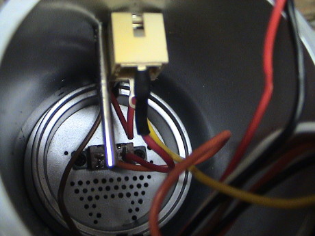
The chuff trigger is a Hall effect device mounted above a tender
axle. A doughnut shaped magnet rides against a rubber roller on the
axle. The Hall effect device is mounted next to the magnet. If the
chuff isn't working right, make sure that the rubber roller is clean
and that the Hall effect device is RIGHT NEXT to the
magnet. Even when it is working, the chuff rate is about half of the
prototypical rate of 4 chuffs/turn.
After the rubber roller gets old and hardens up some it doesn't
provide enough friction to turn the magnet reliably. After much fussing
and fiddling, I finally tried to renew the roller surface with a
coating of contact cement, AND IT WORKED! Pull the wheelset with the
roller from the truck by flexing the truck sideframe slightly and then
paint a layer of contact cement on the roller. Rubber cement would
probably work too. Let it dry for about an hour and reinstall the
wheelset. I do not know how long this patch will last, but even if it
fails after awhile, it would be easy enough to do it again.
I have subsequently done an installation of a Soundtraxx Sierra in this slopeback
tender. This sound quality of the Sierra is much better than the built
in system, but then again, it costs a lot more too.
[ Top ]
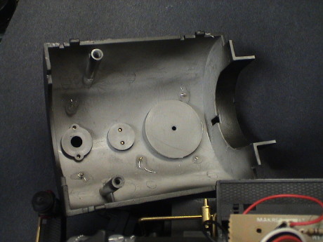
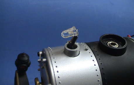
Smoke
The Rogers comes with a smoke system. The system is similar to other
Aristo steamer smoke systems in that it puffs smoke in time with the
drivers, but at only one puff per driver turn. As is typical with
Aristo smoke, the system doesn't generate large quantities of smoke,
but it does smoke for quite a while on the 6 to 7 drop recommend
charge.
The smoke switch is behind the smokebox door (like Bachmann engines)
but it is not labeled so it is easy to forget if the switch is in the
on or off position. Also even the though the smoke generator has its
own switch, the smoke won't work unless the motor is on too.
The smoke unit plugs onto the smoke box so replacing a burnt out
generator should take about 3 seconds.
The instructions say to pour smoke fluid in the opening at the top
of the stack. However, the hole is so small, the first drop plugs up
the little hole. The top cap can be easily pulled off to reveal the
smoke element so that it is much easier to load fluid.
The smoke unit in mine eventually shorted out due to a damaged plug
and it was replaced a Seuthe unit. Seuthe makes LGB smoke units which
are identical. A 16 volt unit works well as this engine usually runs
fairly slowly.
 The center unit in the photo
is the stock Aristo unit. It can be removed from the stack by pushing
it out of the bottom of the stack. The Seuthe unit is slightly larger
in diameter than the Aristo unit so the stack has to be modified for it
to fit. Run a 3/8" drill bit through the stack to ream it out and the
Seuthe element will just fit. A 3.5 mm mono phono plug can be wired to
the smoke element so that the assembly will still plug into the engine
although a pair of needle nose pliers is necessary to insert the plug
before the stack is pressed home.
The center unit in the photo
is the stock Aristo unit. It can be removed from the stack by pushing
it out of the bottom of the stack. The Seuthe unit is slightly larger
in diameter than the Aristo unit so the stack has to be modified for it
to fit. Run a 3/8" drill bit through the stack to ream it out and the
Seuthe element will just fit. A 3.5 mm mono phono plug can be wired to
the smoke element so that the assembly will still plug into the engine
although a pair of needle nose pliers is necessary to insert the plug
before the stack is pressed home.
The hole in the stack cap also can be opened up. A 1/8" hole seems
to work fine.
[ Top ]
Mounting Other Couplers
 A
Kadee #831 coupler can be mounted directly in place of the supplied
Aristo knuckle coupler, however the rear step must be cut to clear the
coupler box. Cutting right next to the step supports will provide
enough clearance for running on 8' diameter curves. To accommodate 4'
diameter curves, more of the step and the inside two step supports
would have to be removed and new step supports fabricated from strip
styrene.
A
Kadee #831 coupler can be mounted directly in place of the supplied
Aristo knuckle coupler, however the rear step must be cut to clear the
coupler box. Cutting right next to the step supports will provide
enough clearance for running on 8' diameter curves. To accommodate 4'
diameter curves, more of the step and the inside two step supports
would have to be removed and new step supports fabricated from strip
styrene.
An LGB knuckle coupler mounts more easily and with no modifications
to the tender required, although some modification to the coupler is
necessary. The mounting groove in the coupler is slightly too narrow to
fit over the coupler mounting tang. I find that a quick pass with a
1/4" motor tool cutter tool will widen the slot in the coupler to allow
it to mount with the original screw in the original hole. The small
cross piece on the coupler shank, the part with the LGB logo on it,
also needs to be ground down to about 1/3 its standard thickness or it
will ride on the rear step and hold the rear wheelset slightly off the
track. After these modifications are made to the coupler, the coupler
height comes out just right.
Mounting a coupler on the engine pilot is not practical. The
overhang on curves would be too large to allow a coupler to work
properly. The pilot does have a drawbar attached.
[ Top ]
Instruction Manuals
Aristo instruction manuals are typically cryptic. The Rogers manual
is better than most, but it could still use improvement. I did find
some problems with the instructions.
Marker Lights. The manual indicates that there are LEDs used
for classification lights. I couldn't find any on the PRR unit that I
had. Lewis Polk informs me that some road names have LED markers and
some do not. The PRR configuration has flag standards instead marker
lamps.
Tender Instructions. My engine didn't come packed with any
instructions for the tender at all.
[ Top ]
Disassembly of the Rogers
 Like
many steam locos, the Rogers isn't extremely easy to take apart, but it
can be done. A good resource for information about the assembly of this
loco can be found on AristoCraft's Exploded Diagrams
page.
Like
many steam locos, the Rogers isn't extremely easy to take apart, but it
can be done. A good resource for information about the assembly of this
loco can be found on AristoCraft's Exploded Diagrams
page.
The saddle tank comes off after removal of two screws under the
walkways (not shown at all in the exploded diagrams) and removal of the
cab. The cab comes off via removal of the rear step. Then the saddle
tank can be squeezed to release four clips and pulled off.
The motor bricks come out from the bottom after removal of the
retainers that hold the posts at the front and back of the brick and
the connecting rods. While it is perhaps possible to get the bricks out
and back in without removing the saddle tank, it is a lot easier to
deal with the connectors on the tops of the bricks with the tank
removed.
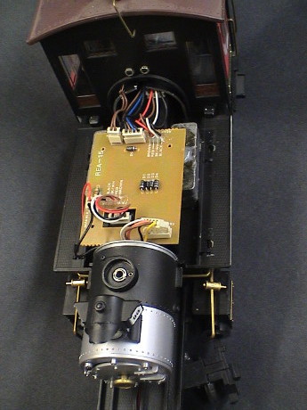
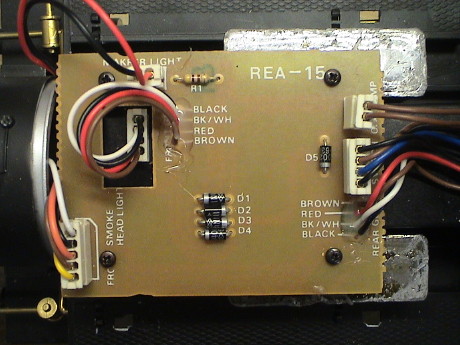
 Even with the
exploded diagrams in hand, I had difficulties removing the saddle tank
to obtain access to the printed wiring board where all the electrical
connections are. The tank should have come off easily, but the PWB was
wide enough so that it had actually ground a groove into one of the
screw posts such that the forward left corner of the tank refused to
release easily. I had to pry it pretty hard to get to pop loose. After
that, I filed some small grooves in the PWB where the posts were and
also ground off a little of the posts so that it would fit
properly.
Even with the
exploded diagrams in hand, I had difficulties removing the saddle tank
to obtain access to the printed wiring board where all the electrical
connections are. The tank should have come off easily, but the PWB was
wide enough so that it had actually ground a groove into one of the
screw posts such that the forward left corner of the tank refused to
release easily. I had to pry it pretty hard to get to pop loose. After
that, I filed some small grooves in the PWB where the posts were and
also ground off a little of the posts so that it would fit
properly.
 The smokebox can
be removed to access the wiring inside. A single screws, accessible
from the left side under the smokebox can be removed. Then the post it
was screwed into is pushed out to the right side. Then the smokebox can
be lifted and turned. There is a hose from a pump in the left cylinder
that provides a little puff for the smoke unit. It needs to be slid off
the metal tube leading up to the base of the smoke unit.
The smokebox can
be removed to access the wiring inside. A single screws, accessible
from the left side under the smokebox can be removed. Then the post it
was screwed into is pushed out to the right side. Then the smokebox can
be lifted and turned. There is a hose from a pump in the left cylinder
that provides a little puff for the smoke unit. It needs to be slid off
the metal tube leading up to the base of the smoke unit.
[ Top ]
Rogers Wiring
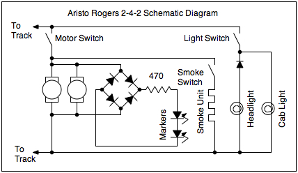 The schematic of the Rogers is pretty
straight forward. The only odd part is that the power for the LED
markers (on units that have them) and for the smoke unit is derived
from the motor terminals so that the markers and smoke will not work if
the motors are not running.
The schematic of the Rogers is pretty
straight forward. The only odd part is that the power for the LED
markers (on units that have them) and for the smoke unit is derived
from the motor terminals so that the markers and smoke will not work if
the motors are not running.
Note that this information is for the "middle age" Rogers. The old
one was a tank engine with a coal bunker in the back of the cab. It may
have similar wiring. I have not seen the "new" one but I have been told
that it has been prewired for battery power so that it's connections
will be different. The spotting feature for that unit would be a square
black connector hanging from under the cab.
 The printed wiring
board itself is a simple one sided assembly. This is the primary
junction point for all of the wiring EXCEPT the rear pony truck power
pickups which appear to connect directly to the rear motor brick. Note
that the black and white wires are the track pickups, but since the two
bricks are reversed with respect to each other, sometimes white and
black join. The motor wires are similarly reversed with respect to each
other.
The printed wiring
board itself is a simple one sided assembly. This is the primary
junction point for all of the wiring EXCEPT the rear pony truck power
pickups which appear to connect directly to the rear motor brick. Note
that the black and white wires are the track pickups, but since the two
bricks are reversed with respect to each other, sometimes white and
black join. The motor wires are similarly reversed with respect to each
other.
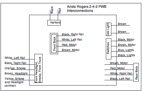 I traced out all the wires. The colors and
functions are shown here.
I traced out all the wires. The colors and
functions are shown here.
[ Top ]
DCC in the Rogers
I went to all the trouble to trace out the wiring because I am going
to install DCC in this Rogers. I have a choice of putting the decoder
in the engine or in the tender. I think that I'll probably put it in
the tender as this will minimize the wiring between the loco and the
tender. Since all the loads in the engine are switched I don't need to
wire them to the decoder to allow programming. Alternately, I could
just put the tender on the programming track.
I will cut the red and brown wires leading to the bricks and connect
the motors together, red to brown. The stubs of wires leading to the
PWB will be insulated and abandoned. This will leave the markers on the
old motor circuit. The motor switch will then become just a marker
switch. The markers will run at constant intensity as they will be
wired directly to the track. I might have to increase the value of the
470 ohm current limiting resistor to about 750 ohms.
With the decoder in the tender I only have to run three more wires
between the engine and tender because the track power pickups are
already wired between the two. Two wires are for the motors. The other
will go to the front headlight (brown) wire. Since the front headlight
is wired to return to a rail along with the smoke unit, I'll have to
cut the red wire inside the smokebox leading from the headlight to the
the smoke unit connector. It will be then reconnected to the positive
terminal of the bridge rectifier (either outside diode toward the
front) that runs the markers to simulate the decoder's "blue" wire. The
headlight will also then be controlled by the old motor switch AND the
DCC decoder. Both will have to be on for the headlight to work.
With the decoder in the tender, connections to the sound triggers to
the Sierra that is already there will be easier. If I put the decoder
in the loco, I'd still have to run two motor wires back to the sound
system, one wire for the rear headlight and four more wires for the
bell, whistle, coupler clank and hiss triggers of the Sierra.
The downside of putting the decoder in the tender is that the loco
will not be able to run by itself. This is common for DCC installations
in steam locos.
The connection to the smoke unit may also require a change. This
loco has a 16 volt Seuthe smoke unit. The DCC track voltage may be a
little high for this unit (depending on what track voltage I end up
with) so I may have to install a small resistor in series with the
smoke unit to drop the voltage to a safe value. I'll determine that
resistor by test after I've done the DCC installation but I expect it
to be in the range of 8 to 24 ohms depending on the track voltage.
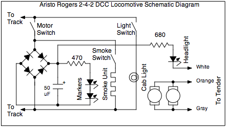 This is a
schematic of the changes that I made to the engine to accommodate DCC.
The actual decoder is installed in the tender. The motors have been cut
loose and wired back to the tender via a 3 wire connector. The third
wire is for the front headlight which was also cut loose from all it's
interconnections and wired back to the tender. I used the bridge
rectifier for the markers to simulate the decoder's blue wire. The
headlight was also changed to a warm white high intensity LED as
described below.
This is a
schematic of the changes that I made to the engine to accommodate DCC.
The actual decoder is installed in the tender. The motors have been cut
loose and wired back to the tender via a 3 wire connector. The third
wire is for the front headlight which was also cut loose from all it's
interconnections and wired back to the tender. I used the bridge
rectifier for the markers to simulate the decoder's blue wire. The
headlight was also changed to a warm white high intensity LED as
described below.
 Most of the work was in the tender.
There was already a Soundtraxx Sierra there, it has been retained. The
rear headlight has also been changed out to an LED.
Most of the work was in the tender.
There was already a Soundtraxx Sierra there, it has been retained. The
rear headlight has also been changed out to an LED.
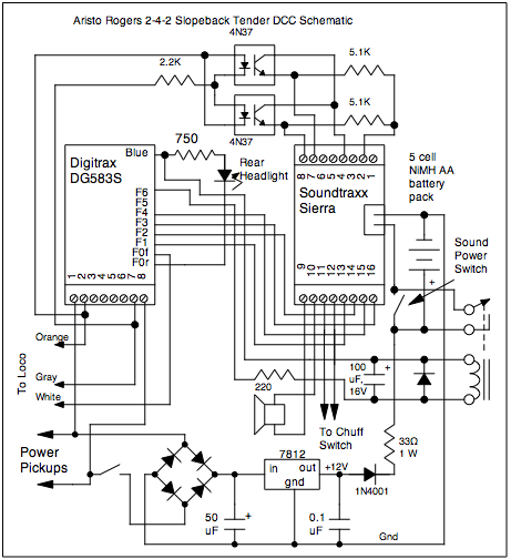
The major additions are the decoder and an interface board which
contains two completely separate circuits. Sierra's have historic
difficulties determining direction when directly connected to a DCC
decoder so I use optical isolators to provide the connection so that
the Sierra can properly blow it's whistle signals. I also use a 12 volt
regulator on this board to act as a battery charger so that whenever
the tender is sitting on powered track, the battery is getting a charge
even if the Sierra isn't turned on. I used the original sound system
slide switch to optionally allow the battery charger to be turned off,
for example during decoder programming. I don't expect to use this
switch much. The bell, whistle, couple clank and blowdown hiss triggers
are wired directly from the Digitrax DG583S decoder.
The relay driven from F6 allows the sound to be turned on remotely.
If the track power goes off, the sound power will go off too. I had a
problem with leaving the manual sound power switch on. If the loco had
been sitting for awhile and the sound system shut itself down, I tended
to forget to turn it off manually before shutting down the layout and
the battery would discharge.
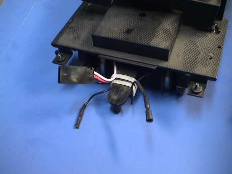 The
three wire connection between the loco and tender is via this swap meet
cable. It had a male connector on one end and a mating female connector
on the other end. I just had to cut the cable and I had both ends. The
business end is securely tied to the drawbar.
The
three wire connection between the loco and tender is via this swap meet
cable. It had a male connector on one end and a mating female connector
on the other end. I just had to cut the cable and I had both ends. The
business end is securely tied to the drawbar.
 The
cable routes through the rear pony truck and up a hole drilled in the
floor. This brings up up inside the backhead when the backhead assembly
is screwed down to the cab floor. The motor leads (brown and red) were
cut near the old connector and the unused stubs insulated with shrink
tube. The front and rear motor wires were connected to the black and
red conductors of the cable going to the tender. Note that the brown
and red motor wires must be connected brown to red as the motor blocks
are identical, but installed physically reversed.
The
cable routes through the rear pony truck and up a hole drilled in the
floor. This brings up up inside the backhead when the backhead assembly
is screwed down to the cab floor. The motor leads (brown and red) were
cut near the old connector and the unused stubs insulated with shrink
tube. The front and rear motor wires were connected to the black and
red conductors of the cable going to the tender. Note that the brown
and red motor wires must be connected brown to red as the motor blocks
are identical, but installed physically reversed.
 At
the front end, the brown wire leading to the headlight was cut and the
stub insulated. Inside the smokebox, the red wire from the headlight
was cut off at the smoke unit connector terminal. Then the headlight
assembly was pulled out of the smokebox for replacement.
At
the front end, the brown wire leading to the headlight was cut and the
stub insulated. Inside the smokebox, the red wire from the headlight
was cut off at the smoke unit connector terminal. Then the headlight
assembly was pulled out of the smokebox for replacement.
The incandescent headlight was junked and an LED installed in it's
place. The red headlight wire was extended and wired back to the bridge
rectifier at the striped end of diode D4. A 50 uF capacitor was
installed between that point and the other side of the bridge and the
non-striped end of D3. This is not really needed for DCC, but it helps
the headlight intensity a lot when the loco is analog converted when
running on PWC. I didn't have to change the 470 ohm current limiting
resistor on the markers. They draw just 20 mA which is a safe value
even though they are not very bright. These are not particularly good
LEDs.
 The
leads on the LED used for the front headlight were formed to allow the
LED to sit inside the headlight housing at the right height. A 680 ohm
current limiting resistor is installed in one lead. The leads were
insulated with shrink tubing and the assembly was attached to the inner
surface of the headlight mounting tube with a small amount of Zap-A-Gap
CA. The headlight housing can then be slipped over the LED and
reattached with it's original screw. The rear headlight was done the
same way but a 750 ohm resistor was used because I couldn't find
another 680.
The
leads on the LED used for the front headlight were formed to allow the
LED to sit inside the headlight housing at the right height. A 680 ohm
current limiting resistor is installed in one lead. The leads were
insulated with shrink tubing and the assembly was attached to the inner
surface of the headlight mounting tube with a small amount of Zap-A-Gap
CA. The headlight housing can then be slipped over the LED and
reattached with it's original screw. The rear headlight was done the
same way but a 750 ohm resistor was used because I couldn't find
another 680.
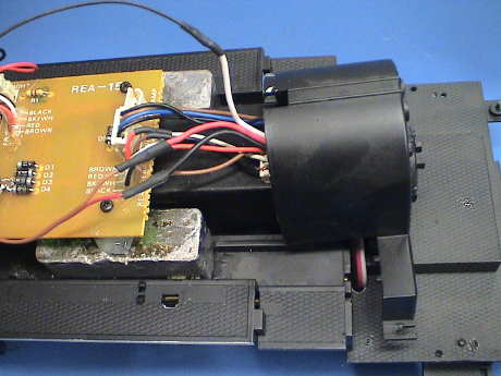
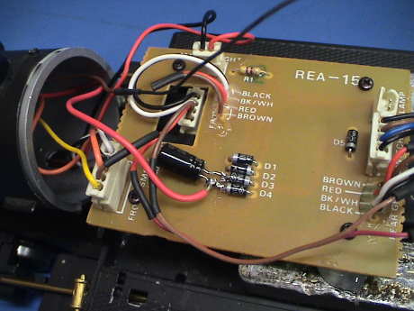
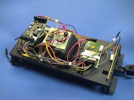 The
tender is the most complex. The sound system sits atop the speaker,
held down with double back foam tape. It is accessible through the open
coal load for programming. A perforated board is mounted with foam tape
on top of the replacement battery for the Sierra. This is a 5 cell AA
NiMH pack and has been completely trouble free for years. The decoder,
a Digitrax DG583S, is mounted with foam tape to the tender floor at the
rear. The existing slide switch about halfway along the fireman's side
is used to control the power to the battery charger. The toggle switch
I originally installed with the Sierra disconnects the Sierra from it's
battery to that the Sierra doesn't flatten the battery during storage.
The battery charger provides about 150 ma of charge rate for the
battery. When the system is running, the battery is about charge
neutral on the average.
The
tender is the most complex. The sound system sits atop the speaker,
held down with double back foam tape. It is accessible through the open
coal load for programming. A perforated board is mounted with foam tape
on top of the replacement battery for the Sierra. This is a 5 cell AA
NiMH pack and has been completely trouble free for years. The decoder,
a Digitrax DG583S, is mounted with foam tape to the tender floor at the
rear. The existing slide switch about halfway along the fireman's side
is used to control the power to the battery charger. The toggle switch
I originally installed with the Sierra disconnects the Sierra from it's
battery to that the Sierra doesn't flatten the battery during storage.
The battery charger provides about 150 ma of charge rate for the
battery. When the system is running, the battery is about charge
neutral on the average.
This all worked out pretty well. I may have some decoder tweaking to
do because the lowest speed is a little higher that I like but overall,
all is well.
[ Top ] [ Home ] [ Up ] [ Previous Page ] [ Next Page ]
This page has been accessed  times since May 5, 1998.
©1998-2009 George Schreyer
Created May 5, 1998
Last Updated February 14, 2010
 22 Sep 08
 26 Sep 08