Aristo Classic Rail Bus Tips
[ Home ] [ Up ] [ Previous
Page ] [ Next Page
]
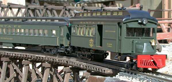
 Aristo has recently released their version of a
rail bus. The rail bus evolved to fill a need on narrow gauge,
shortline and branchline railroads. As passenger traffic dropped
off due to competition from automobiles and highway busses, the
railroads could no longer afford to run a regular steam engine
which pulled maybe one coach. To reduce costs an old wooden coach
was often cut up and grafted to an large automobile or truck frame.
The original gasoline engine and manual transmission were
sufficient to haul the rail bus, and on some lines, maybe an
additional coach if the grades were mild. The rail busses kept
these struggling railroads in business for a few extra years, but
eventually most of these roads folded anyway.
Aristo has recently released their version of a
rail bus. The rail bus evolved to fill a need on narrow gauge,
shortline and branchline railroads. As passenger traffic dropped
off due to competition from automobiles and highway busses, the
railroads could no longer afford to run a regular steam engine
which pulled maybe one coach. To reduce costs an old wooden coach
was often cut up and grafted to an large automobile or truck frame.
The original gasoline engine and manual transmission were
sufficient to haul the rail bus, and on some lines, maybe an
additional coach if the grades were mild. The rail busses kept
these struggling railroads in business for a few extra years, but
eventually most of these roads folded anyway.
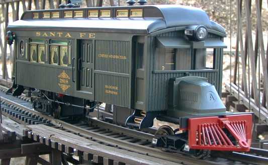
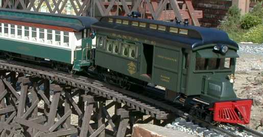
The model represents a wooden coach body grafted to a Mac
Bulldog truck frame but without the Mac chain drive.
Jeff Saxton writes:
"Actually, about 75% of ALL railbuses were factory-built jobs,
very few, relatively, were home-built, and I know of NO Mack based
home built railbus; all are factory models with steel carbodies on
the "AC" hood version (the famous chain drive Bulldog which Aristo
replicates), although wood carbodies were used on the smaller
(direct transmission) "AB" models. Mack "AC" Bulldogs date from
around 1915 to 1938 -- and Aristo's choice of radiator design dates
it as post 1921 if I recall correctly.
Single drive axle Mack "AC" railbuses are model "ACR", while
double axle versions are "ACX" models, and none were chain drive,
but direct transmission. Mack made the first ACR in 1916, so quite
early overall. Aristo molded an "A" in the hood, I assume for
Aristo, since licensing from "Mack Trucks Inc." went to Hartland
for their forthcoming Mack bus, which will be similar. The real
hoods should have the parent company's "International Motors" with
the "flying I-M" logo on the hood.
Mack also made some "AL" and "AM" based chassis into railbuses
-- these chassis were used in the line of highway buses and fire
engines Mack produced -- more cylinders -- more horsepower."
Contents
Performance and Detail
 The Aristo Classic Rail Bus is a very smooth
running model. Power pickup is on all eight wheels and is very
steady. The wheels themselves do not appear to be susceptible to
pitting so that they tend to stay clean. The motor runs very
smoothly. The bus will maintain very slow speeds at about one tie
per second. It'll go slower on straight track, but the additional
load when transitioning to a 2' radius turn will stall it. Like
most direct worm gear drives, the bus has a slight tendency to
lurch at some speeds and loads on some downgrades.
The Aristo Classic Rail Bus is a very smooth
running model. Power pickup is on all eight wheels and is very
steady. The wheels themselves do not appear to be susceptible to
pitting so that they tend to stay clean. The motor runs very
smoothly. The bus will maintain very slow speeds at about one tie
per second. It'll go slower on straight track, but the additional
load when transitioning to a 2' radius turn will stall it. Like
most direct worm gear drives, the bus has a slight tendency to
lurch at some speeds and loads on some downgrades.
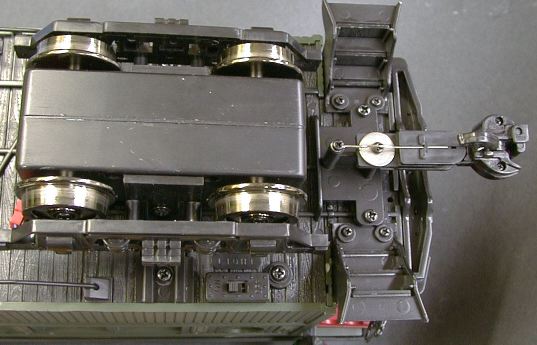
The bus has one dicast motor block similar to the one used in
the Center Cab Industrial Switcher.
The wheels on the rail bus are slightly smaller. The front truck is
an unsprung archbar design with ball bearing wheels and electrical
pickups. The rear truck sideframes represent a typical equalized
coach truck. The motor block also picks up power on all four wheels
through ball bearings.
The bus runs very smoothly and quietly and is tolerant of
moderately dirty track due to the 8 point power pickup. Sometimes
the bus tends to wobble a little, but then again, real rail busses
did that too. The wobble appears to occur when the bus goes through
turnouts. The wheel flanges are a little smaller than the
"standard" large scale flange which allows the wheels to drop into
the frogs.
The model has no extra weighting except for the weight of the
cast motor brick so its traction is fairly weak. It will handle one
additional coach on a 4% grade, more than that and it starts to
slip. However, a real rail bus often struggled just to drag itself
around so this "feature" is prototypical too. One couldn't expect a
4 cylinder flathead gasoline motor to pull a whole train. I did run
my standard Tractive
Effort Tests on the rail bus and it did fairly well, pulling
about as well as other locos with 4 driven wheels.
The bus appears to be very tolerant of out of level or gauge
track and did not derail on its own at all during testing on both
the GIRR or the GIRR Mountain Division layouts. On the first pass
over the Mountain Division, the smokestack whacked an overhead
support quite solidly and the bus derailed then. The stack has
since been lowered so this is no longer a problem. The rail bus is
a little too light in the front to push over the points of an LGB
1200 turnout while going forward, but it will do it in reverse.
I did notice that the power brick wheels didn't seem to be
evenly resting on the track when the bus was going over vertical
track gradients (the GIRR Mountain Division has one spot that needs
fixing). The A-frame that mounts the power brick doesn't have much
play to allow it to rock fore and aft like the A-frames in the
Center Cab Industrial switcher do. Loosening the two brick mounting
screws on the sides of the A-frames a half a turn each allowed the
brick to rock a little more within the A-frame and then the unit
tracked better over the uneven track.
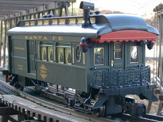
The Aristo model is very well detailed. The grating on the back
of the bus is a metal casting with operating gates and platform
drop panels. The rear and side doors operate, but the driver's
doors do not. The paint and lettering is excellent and there are
curtains simulated in the windows. The panels above the windows are
tinted dark green. There is no driver in the bus, this'll have to
get fixed.
There is a smoke unit that represents smoke from a pot bellied
stove at the rear of the coach. In typical Aristo fashion, the unit
doesn't generate huge volumes of smoke, but the smoke plume is
visible with the bus running at about half speed while using an
Aristo PWC power pack. The smoke unit doesn't make much smoke at
all with a standard DC power pack except at full throttle. The
smoke unit is removable, it just unplugs like many other Aristo
smoke units.
The model has both interior and exterior lighting. There are
four interior lights installed in fixtures on the walls. The rear
markers are illuminated as is the cab. The headlight operates but
is not directional. There are switches underneath near the rear
truck. One controls the smoke unit and the other controls the motor
and lights. It would have been nice to be able to turn just the
motor off so that the bus could sit lighted and smoking. Without
some rewiring, this cannot be done. The wiring is inside the floor
of the unit so that some significant disassembly will be required
to access the wiring.
The truss rods are metal and the metal turnbuckles actually
thread on. However, the turnbuckles are not reverse threaded so
that it is not possible to "adjust" the truss rods with the
turnbuckle.
 The Aristo Classic Rail bus represents a
typical combo coach type of bus. The bus was divided into three
parts, a driver's compartment, small baggage, mail and freight
section, and a coach section. These busses typically stopped
anywhere on the line where somebody flagged them to pick up or drop
off passengers, mail and freight. The baggage compartment is easily
big enough to hold a sound system, batteries and a control
receiver.
The Aristo Classic Rail bus represents a
typical combo coach type of bus. The bus was divided into three
parts, a driver's compartment, small baggage, mail and freight
section, and a coach section. These busses typically stopped
anywhere on the line where somebody flagged them to pick up or drop
off passengers, mail and freight. The baggage compartment is easily
big enough to hold a sound system, batteries and a control
receiver.
The roof is attached with four screws. Two are easily accessible
under the rear awning. To access the other two, remove the front
steps and look in the front corners of the roof for the other two
screws. It takes a fairly long #1 Phillips screwdriver to reach
them. Don't pull them all the way out. The flanges on the body are
threaded and the screws will stay in place if pulled out just far
enough to release the roof. This makes getting the roof back on
much easier.
[ Top ]
Scale and Clearance
 Aristo built this model around a narrow
gauge 1/24 scale Sierra combo coach but the model is identified as
1/29 scale. However the general proportions of the model are much
larger than other 1/29 scale equipment. It is nearly an inch taller
than a standard heavyweight coach.
Aristo built this model around a narrow
gauge 1/24 scale Sierra combo coach but the model is identified as
1/29 scale. However the general proportions of the model are much
larger than other 1/29 scale equipment. It is nearly an inch taller
than a standard heavyweight coach.
 The Rail
bus is even 1/2" taller than a Bachmann coach (the scale of the
Bachmann coach is debatable). The rear door of the rail bus is just
over 6' tall in 1/29 scale so this comes out ok, but the driver's
door is nearly 8' tall in 1/29 scale. Based on the match to other
coaches, the rail bus would look more appropriate on a 1/24 scale
1930's era narrow gauge layout than a more modern standard gauge
one.
The Rail
bus is even 1/2" taller than a Bachmann coach (the scale of the
Bachmann coach is debatable). The rear door of the rail bus is just
over 6' tall in 1/29 scale so this comes out ok, but the driver's
door is nearly 8' tall in 1/29 scale. Based on the match to other
coaches, the rail bus would look more appropriate on a 1/24 scale
1930's era narrow gauge layout than a more modern standard gauge
one.
The front and rear steps are way off the ground, The step down
is over 2' in 1/24 scale, even higher in 1/29 scale. The bus is
just a little too tall. This appears to be a result of the size of
the power brick. It is tucked pretty tightly against the floor of
the bus so it would appear that the only way to lower the bus would
be to recess the brick up into the coach floor, a fairly major hack
job.
The rail bus is 21" long from the tip of the pilot to the rear
coupler. The bus is 4-1/4" wide over the body and 5-3/8" wide over
the marker lamps. This is wider than most other large scale rolling
stock so if you have restricted side clearances there may be some
difficulty. There were a couple of hidden spots on straight track
at the GIRR Mountain Division where the markers dragged against
adjacent layout structures. Nothing else had ever dragged at these
spots, so the rail bus is actually wider than any other stock that
I already had. I was able to adjust the track centerline to split
the difference and the bus barely passed without other structural
work.
The roof line extends 6-1/2" from the railheads. There are four
vents on the roof that are 1/4" taller and the smokestack extends
to 7-1/8" from the railheads.
The worst overhang on a 2' radius curve is the rear step at
2-3/8", just a little less than a Big Hauler, so that the rail bus
will probably fit on most railroads that don't have vertical
clearance problems.
The smokestack didn't clear some rather hard limits on my indoor
layout and it needed some work. I reduced the height of the stack
by a little more than 1/4". I pulled the stack off the metal heater
assembly and cut 1/4" off the stack after removing the smokejack.
The smokejack was then reinstalled as close to the top of the stack
as possible. New screw holes were drilled with a #55 drill using
the smokejack as a template. The heater element now sticks out of
the top of the stack by about 1/16" but is protected from damage by
the smokejack.
The motor brick sits quite low due the small wheels. It will
hang up on LGB automatic uncoupling tracks which lift the drive
wheels barely off the track. If the bus is going to slowly when it
crosses an uncoupler, it will stop dead with the wheels spinning,
high centered on the motor brick. The center cab switcher uses the
same brick, but has larger wheels so that it just clears the
uncoupling ramp.
[ Top ]
Couplers
 The rail bus
comes equipped with a body mounted standard Aristo knuckle coupler.
A hook and loop coupler is supplied in the box. The coupler is
mounted so that it can swivel but it still puts quite a bit of
twisting force on a following car in a tight turn. The following
car does not actually derail, but its trying to. The pilot has a
drawbar attached.
The rail bus
comes equipped with a body mounted standard Aristo knuckle coupler.
A hook and loop coupler is supplied in the box. The coupler is
mounted so that it can swivel but it still puts quite a bit of
twisting force on a following car in a tight turn. The following
car does not actually derail, but its trying to. The pilot has a
drawbar attached.
 I mounted
an LGB knuckle coupler to the rail bus. The mount required some
modification but the changes were not difficult. The LGB coupler
mounts directly to the existing coupler post. Some small pieces of
styrene are used to fabricate the centering spring capture feature
that was on the original coupler. The centering spring needs to be
formed differently to clear the back of the LGB coupler tang and
mounting screw.
I mounted
an LGB knuckle coupler to the rail bus. The mount required some
modification but the changes were not difficult. The LGB coupler
mounts directly to the existing coupler post. Some small pieces of
styrene are used to fabricate the centering spring capture feature
that was on the original coupler. The centering spring needs to be
formed differently to clear the back of the LGB coupler tang and
mounting screw.
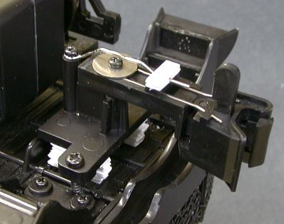
The stock Aristo centering spring as shown in the photo is bent
from 0.035" wire. This turns out to be a little too stiff for use
with the LGB knuckle couplers. The Railbus will often drag the
following car off the track in a turn or a turnout. I hand bent
another spring from 0.025" music wire which seems to have fixed
this problem.
The coupler comes out 3/8" too high so that the entire bracket
was spaced downward with styrene shims to put the coupler at the
right height. It took two stacks of six pieces of 0.062" styrene to
build a shim of the correct height. The screws that hold the
coupler bracket also hold the rear platform in place. The stock
screws are too short to reach with the shim installed so longer
screws were substituted. The mounting screw holes in the bracket
were threaded which is a little unusual. I drilled them out so that
the screws had a clearance fit in the bracket.
It would appear that a Kadee coupler could be mounted in the
same fashion.
[ Top ]
Disassembly of the Railbus
Getting into the Railbus far enough to install passengers, a
driver, sound or RC control isn't too difficult. Getting into it
far enough to get to the printed wiring board inside the floor is
much more difficult. There is an exploded diagram of the Railbus at
the AristoCraft Internet
Depot.
The roof comes off pretty easily. There are two screws under the
rear corners of the roof. These are flat head screws set into the
red awning piece in the rear. The front two screws are way up
inside the front corners. The front steps need to be removed to
access the roof screws. These screws will not come all the way out.
This is good because it would be hard to get them back in. They
will back out far enough to release the roof though and they stay,
captive, in place.
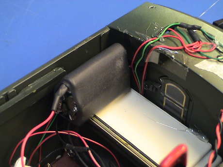
The whole front end assembly with the front frame, front truck,
pilot, cab and engine hood comes off with two screws that are set
into the gas tanks. There are two wires that need to be unsoldered
to completely release the front end. Pull the shrink tubing back
where they wires enter the floor and unsolder the wires at the
posts there.
Once the front end is off, the cab will just pull down and
forward and release. It will still be captive by some wires, but
you can get far enough in to install a driver. There isn't much
room in the cab, most sitting figures will need their legs cut off
to fit.
Taking the rest of it apart is a challenge that I elected not to
attempt as I didn't need to.
[ Top ]
Wiring in the Railbus
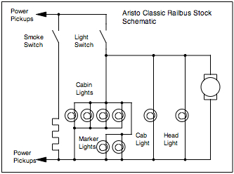 I
have not disassembled the Railbus far enough to visually inspect
the wiring, but it has to be pretty simple and this schematic
describes it's behavior. There are two switches under the body near
the rear truck, one is labeled "Smoke" and the other "Lights." The
only issue is that the motor and lights are switched together. The
headlight is non-directional but that could be easily changed with
the addition of a diode in a headlight wire.
I
have not disassembled the Railbus far enough to visually inspect
the wiring, but it has to be pretty simple and this schematic
describes it's behavior. There are two switches under the body near
the rear truck, one is labeled "Smoke" and the other "Lights." The
only issue is that the motor and lights are switched together. The
headlight is non-directional but that could be easily changed with
the addition of a diode in a headlight wire.
[ Top ]
Sierra Sound Installation in the
Railbus
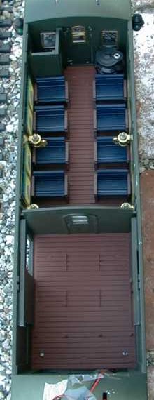
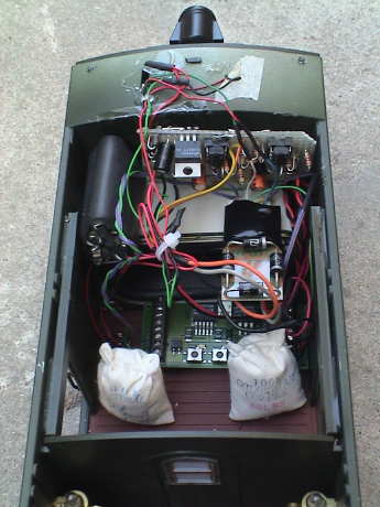
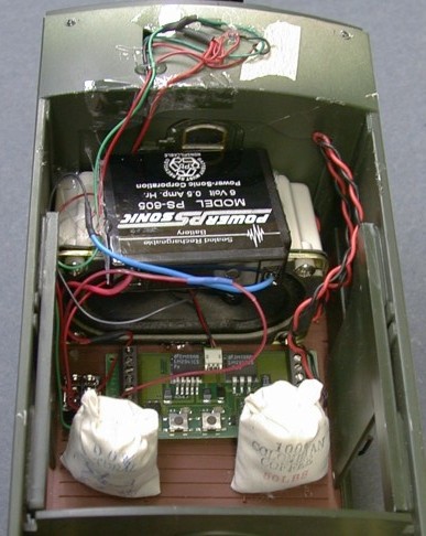 Sound
installation in the Railbus isn't too difficult depending on where
you mount the speaker. I used another of my swap meet computer
speakers in the baggage compartment pointing rearward. These
speakers have their own cabinet so I didn't have to worry about
sealing anything up. The sound comes out the open cargo doors. The
battery is hot glued to the top of the speaker box. The sound card
itself is attached to the floor with double backed foam tape right
behind the speaker so that the programming buttons can be reached
through the doors. I hot glued a couple of bags of coffee to act as
view blocks so that the card cannot be seen looking through the
doors. Power for the installation is tapped from the headlight
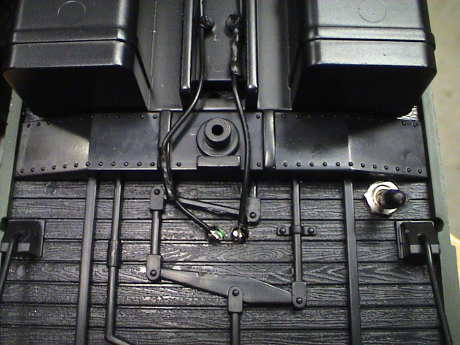
wiring above the cab. The power switch (switching both track power
and the battery) is mounted in a hole in the floor. This hole was
drilled about 1/2" in from the edge of the floor, right behind the
unused bolster casting in the floor.
Sound
installation in the Railbus isn't too difficult depending on where
you mount the speaker. I used another of my swap meet computer
speakers in the baggage compartment pointing rearward. These
speakers have their own cabinet so I didn't have to worry about
sealing anything up. The sound comes out the open cargo doors. The
battery is hot glued to the top of the speaker box. The sound card
itself is attached to the floor with double backed foam tape right
behind the speaker so that the programming buttons can be reached
through the doors. I hot glued a couple of bags of coffee to act as
view blocks so that the card cannot be seen looking through the
doors. Power for the installation is tapped from the headlight
wiring above the cab. The power switch (switching both track power
and the battery) is mounted in a hole in the floor. This hole was
drilled about 1/2" in from the edge of the floor, right behind the
unused bolster casting in the floor.
There is a circuit board in the floor somewhere and I didn't
want to drill holes through the floor to let the sound escape. I
probably would have drilled right through something important on
the board. This is why I choose the door method. Since the buttons
on the Sierra can be reached, an external volume/programming switch
is not required.
I choose a Sierra RGS Goose sound system for this install, I
guessed that it would be close. While the Sierra system sounds
good, its speed doesn't match the Railbus speed well unless you
accelerate and decelerate quite slowly. The shifts are distinct,
but the engine sound doesn't "spool" well between shifts. The
system also sounds a dynamic brake and air compressor pop off as
delivered. These should be turned off, there weren't too may
Railbuses with dynamic or air brakes.
 As
I was ripping into the Railbus to install DCC, I elected to replace
the Sierra gelcell battery with a 5 AAA cell NiMH pack that I had
assembled for the Bachmann Railtruck. Only after I had made the
pack did I find out that I couldn't get a Sierra for it because the
Sierra has been discontinued. The existing battery was six years
old so I figured that it had lasted well past it's expected
life.
As
I was ripping into the Railbus to install DCC, I elected to replace
the Sierra gelcell battery with a 5 AAA cell NiMH pack that I had
assembled for the Bachmann Railtruck. Only after I had made the
pack did I find out that I couldn't get a Sierra for it because the
Sierra has been discontinued. The existing battery was six years
old so I figured that it had lasted well past it's expected
life.
[ Top ]
DCC Installation in the Railbus
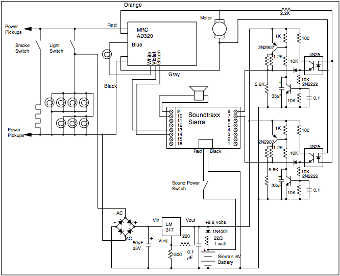 This is the schematic of the DCC
installation in the Railbus. There is a lot of stuff here, but this
is what it takes to get a Sierra to work properly with DCC or most
RC systems. The Railbus uses a "diesel" version of the Sierra, but
programmed with the sounds of a Goose. The diesel systems do not
detect the start and stop events reliably without optical isolators
between the motor and the Sierra. The optical isolators fix the
start and stop sounds, but they screw up the coordination between
the sound of the motor revving up and the actual speed of the
Railbus. This circuit looks a little involved, but it fixes all
that, see my Soundtraxx Sierra
Tips page for more information. The circuit itself is built on
a small piece of perforated board that is mounted above the speaker
on the forward wall.
This is the schematic of the DCC
installation in the Railbus. There is a lot of stuff here, but this
is what it takes to get a Sierra to work properly with DCC or most
RC systems. The Railbus uses a "diesel" version of the Sierra, but
programmed with the sounds of a Goose. The diesel systems do not
detect the start and stop events reliably without optical isolators
between the motor and the Sierra. The optical isolators fix the
start and stop sounds, but they screw up the coordination between
the sound of the motor revving up and the actual speed of the
Railbus. This circuit looks a little involved, but it fixes all
that, see my Soundtraxx Sierra
Tips page for more information. The circuit itself is built on
a small piece of perforated board that is mounted above the speaker
on the forward wall.
The interface circuit was built and tested while the desired
decoder was on backorder. I tested the circuit using an Aristo
ART-5490 as a source of motor drive and it worked fine. However, I
elected to install an MRC AD320 decoder to test the rest of the
installation and I had to make some changes the the circuit. The
AD320 is a low frequency decoder. It was surplus because it had
made too much noise in previous installations but it only made only
a very faint buzzing noise in the Railbus. Otherwise, it worked
fine. However the interface circuit didn't work right because it
had been designed and tested with high frequency pulses. The long,
low frequency pulses made by the AD320 were too long and the
interface circuit wasn't remembering it's state between pulses. I
added a 33µF capacitor at the collector of the 2N2222 to
prevent the collector voltage from rising between pulses. I also
changed the output divider network a little to tease the output
voltage up just a little so that the sound system would start to
ramp up on the first speed step of the 28 step decoder.
Contrary to the exploded parts diagram on the AristoCraft site,
my motor block has four wires coming out going to two connectors. I
had another set of these connectors so isolating the motor was as
easy as identifying which connector is for the motor and
disconnecting it. I then used one side of a mated pair of spare
connectors that I have to reconnect to the motor. Track power for a
decoder cannot be picked up from the motor leads leading from the
body as the motor is switched along with the lights. Separate
switching of the lights is needed to allow service mode programming
on a programming track.
 However, track power contacts can be accessed at these two
terminals near the fuel tanks. These are raw and unswitched track
power.
However, track power contacts can be accessed at these two
terminals near the fuel tanks. These are raw and unswitched track
power.
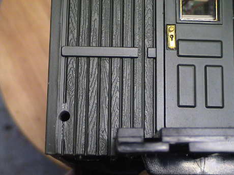 Getting
the four wires (two for the motor, two for unswitched track power)
back inside is a little more difficult. There is a PWB inside the
floor but it appears to be narrow judging from the exploded parts
diagram. One SHOULD be able to drill up through the floor(s) and
miss it, but it is not necessary to take that risk. Instead, drill
a hole in the front wall behind the engineer. This hole comes
through just above the floor inside without the risk of drilling
through something important. The wires can snake across the bottom
of the loco and go up around a front step. This hole isn't in the
perfect spot, it wants to be nudged inward just a little as the cab
door blocks part of it when the cab is installed.
Getting
the four wires (two for the motor, two for unswitched track power)
back inside is a little more difficult. There is a PWB inside the
floor but it appears to be narrow judging from the exploded parts
diagram. One SHOULD be able to drill up through the floor(s) and
miss it, but it is not necessary to take that risk. Instead, drill
a hole in the front wall behind the engineer. This hole comes
through just above the floor inside without the risk of drilling
through something important. The wires can snake across the bottom
of the loco and go up around a front step. This hole isn't in the
perfect spot, it wants to be nudged inward just a little as the cab
door blocks part of it when the cab is installed.
 This is
the final installation with the AD320. This old decoder is working
well enough that it might just stay in there. Power for the
interface circuit is picked off the lighting wires above the cab.
The battery charges via the interface circuit board and these two
wires all the time that the lights are on and the Railbus is
sitting on powered track. The AD320 gets it's track power from the
two terminals underneath the floor right behind the fuel tank. The
motor leads are also snaked across the bottom of the Railbus to a
connector that plugs into the motor brick. The AD320 has two
function outputs besides the headlights. These are wired to the
Sierra to manually trigger the bell and horn.
This is
the final installation with the AD320. This old decoder is working
well enough that it might just stay in there. Power for the
interface circuit is picked off the lighting wires above the cab.
The battery charges via the interface circuit board and these two
wires all the time that the lights are on and the Railbus is
sitting on powered track. The AD320 gets it's track power from the
two terminals underneath the floor right behind the fuel tank. The
motor leads are also snaked across the bottom of the Railbus to a
connector that plugs into the motor brick. The AD320 has two
function outputs besides the headlights. These are wired to the
Sierra to manually trigger the bell and horn.
The AD320, the interface board, the battery and the Sierra are
all held in place with pieces of foam mounting tape.
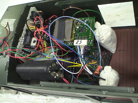 The AD320 did not
stay in the Railbus. It was working fine but I needed it elsewhere
because it was just small enough to fit in James. I also wanted an extra
function output to drive a sound enable relay. It's getting pretty
busy in there now with the speaker, Sierra, battery for the Sierra,
interface circuit for the Sierra, DCC decoder and sound enable
relay. The relay is down on the floor between the sacks. This all
works and I didn't have to change anything on the Sierra interface
circuit to accommodate the high switching frequency of the Digitrax
DG583S decoder.
The AD320 did not
stay in the Railbus. It was working fine but I needed it elsewhere
because it was just small enough to fit in James. I also wanted an extra
function output to drive a sound enable relay. It's getting pretty
busy in there now with the speaker, Sierra, battery for the Sierra,
interface circuit for the Sierra, DCC decoder and sound enable
relay. The relay is down on the floor between the sacks. This all
works and I didn't have to change anything on the Sierra interface
circuit to accommodate the high switching frequency of the Digitrax
DG583S decoder.
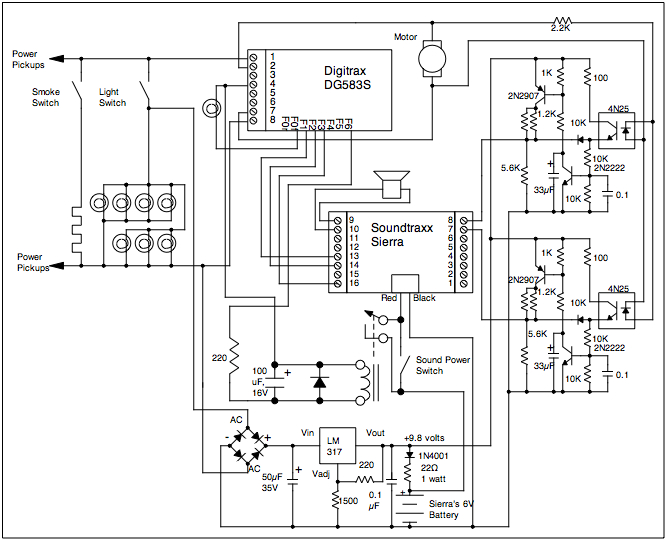 This is the revised schematic of
the "final" DCC installation in the Classic Railbus. The relay
allows the decoder to activate the sound system in parallel with
the manual switch. When the decoder controls the sound system, the
sound system will shut down when the decoder commands it or track
power shuts off. This allows me to "forget" to turn it off, it'll
go off by itself and not discharge the battery.
This is the revised schematic of
the "final" DCC installation in the Classic Railbus. The relay
allows the decoder to activate the sound system in parallel with
the manual switch. When the decoder controls the sound system, the
sound system will shut down when the decoder commands it or track
power shuts off. This allows me to "forget" to turn it off, it'll
go off by itself and not discharge the battery.
[ Top ] [ Home ] [ Up ] [
Previous Page ] [ Next Page ]
This page has been accessed  times since 22 July 00.
© 2000-2009 George Schreyer
Created July 22, 2000
Last Updated February 3, 2009
 26 May 02
 8 Oct 08